| Previous Contents Index DocHome Next |
| iPlanet Unified Integration Framework Developer's Guide |
Chapter 1 Concepts
This chapter describes the iPlanet Unified Integration Framework (UIF) concepts you should be familiar with before you set up iPlanet UIF or use the Application Programmable Interface (API) in your servlets or Enterprise JAVA Beans (EJBs).This chapter contains the following sections:
About UIF
UIF is used to build interactive web-based applications. Specifically, UIF allows you to access data on enterprise information systems and applications from a servlet or EJB controlled by an iPlanet Application Server (iAS).The following sections describe:
Architecture
Architecture
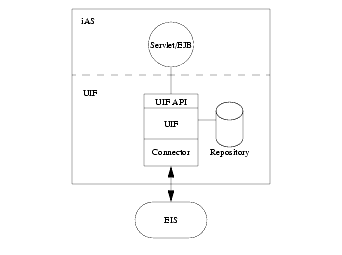
The following figure shows the relationship between a servlet or EJB running in iAS, UIF, and an EIS Enterprise Information System (EIS).
UIF architecture includes a common UIF API used to access data, a UIF data repository, and an connector that implements the specific EIS data access services.
The UIF module provides uniform access and all data source views. Programmers use the UIF API to uniformly access data. A platform specific connector provides the translation and data marshalling between UIF and the EIS system. The UIF repository holds parameters and information about the EIS system. For example, the connection definitions, EIS datatype, and EIS business functions.
UIF Abstractions Overview
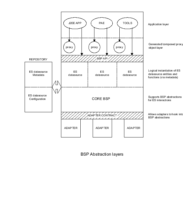
The following figure shows the UIF abstraction layers, their components and functions.
Future: business objects - proxification and composition of EIS business functions
EIS datasources - each represents a given EIS instance
EIS data source business entities and business functions - metadata representing datatypes, and instances of EIS specific unit of interaction (stored procedures, BAPIs, message definitions, event definitions etc.)
Function object - defines EIS specific unit of interaction (stored procedure, RFC, message, event etc.)
Data object - unified hierarchical data representation object
Interaction model - sync request/response (future: async send/receive, message based, pub/sub)
Supports abstractions for unit of interaction (function object), interaction model, communication model
Supplies core services for resource management, thread management, communication context lifecycle management, exception management, etc.
Repository and Metadata Services
Models a persistent information hierarchy
Supports data type definition, and inheritance and encapsulation relationships between datatypes
Manages instantiation (and reuse) of data objects from data type definitions
Implements a self describing, lightweight and performant representation of hiearchical data
UIF Abstractions Detailed
The following figure shows a detailed view of UIF components.
Data Object Service
This service implements a universal data representation object. A Data Object (DO) is a hierarchical data representation object, somewhat like C/C++ structures. They can contain structures, arrays and lists, nested to arbitrary levels. DOs are self describing and introspectable. Programmatically, one can address into a DO using path names like A.B[2].C. One can iterate over a DOs contents using iterators.DOs are used to pass all information and data across API boundaries between: the application and UIF, and between UIF and the connector. The structural flexibility and introspectability of DOs allows the contract between these three layers to be well defined and fixed, yet allow interaction with any given backend EIS.
Creation and destruction of DOs has a potentially high performance penalty due to their dynamic structure and flexibility. This is optimized via memory management techniques and object reuse (freelists). These freelists are managed by the metadata service.
The DO API is highly exposed to the user, since the application sends and receives all data as data objects.
Repository Service
This service models a persistent hierarchy of information - somewhat like LDAP, but with higher level data contents. Persistence is implemented on top of LDAP. The service API is not exposed to the application. The users of the repository service are mainly the UIF runtime and the management console.Leaf nodes in the repository can be either primitive key value nodes, or complex data object type definition (dataTypes) nodes. The metadata service uses a data type definition to create a data object of that type. Most data type nodes in the repository represent metadata mined from backend ES. They define types for parameter datablocks, configuration info blocks, user mapping structures, etc.
Data type nodes can embed and reuse other data type definitions. Also, since a given data type can be used in multiple contexts, there is a mechanism to initialize values of a data type's fields in different contexts. This is achieved via a template node, which includes a data type reference, and a set of initial values for the fields in the dataTypes.
No update/edit API is provided by the repository service. Repository service maintains a read only cache of objects, populated lazily (on demand). The cache does not refresh itself from LDAP once loaded. Therefore, any changes in LDAP does not reflect in the service until KJS is restarted. This is good, since the repository contains information which determine connector behavior, and it's contents cannot be used while in an inconsistent state.
There is a Repository Browser tool which allows user to explore repository contents. The tool has no editing feature. However, it does provide import, delete and export actions on repository nodes.
Repository contents are modified/populated via an import function which can be programmatically and interactively invoked. This feature is available as a browser function and as a command line tool. The function imports XML (as per a specified DTD) under a specified repository node. The export function is also available via repository browser and command line. It exports any subtree as an XML document.
Although the repository service does not impose any specific organization (schematics) on the repository contents, the UIF runtime does require the contents to be organized in a specific and well defined way. This organization is the UIF repository schematics. The UIF runtime expects to specific information in specific places in the repository hierarchy, much as iAS does in GDS. Therefore, repository contents are not supposed to arbitrarily modified by the user (even though the import and delete functions are exposed). Contents are modified as part of specific administration activities controlled by the management console, which makes appropriate programmatic use of the import and export functions. In addition, the UIF runtime service runs a consistency check on repository contents at startup.
Metadata Service
This service is responsible for instantiating data objects from data type and template definitions in the repository. It also manages object reuse via freelists of data objects. These freelists are organized by data type, and allows the administrator to set upper bound on memory usage, as well as other tuning parameters. Feelists greatly reduce the number of objects being created and destroyed, and add substantially to UIF performance.The metadata service API is not exposed to the application. User does not explicitly create data objects. DOs are created in association with Function Objects and Service Provider objects, which is what the application explicitly creates. Thus, the metadata service is used mainly by the UIF runtime service.
Repository Schematics
The UIF runtime requires a specific organization in the repository. There is currently no mechanism to enforce this organization; however, there is a command line (and repository browser) function to check the organization. In addition, the UIF runtime runs a schematics validation check at startup.Broadly, the organization is as follows: there are two sections - connectorTypes and dataSources.
The connectorTypes section contains one subtree entry per connector. The entry contains common definitions which form the basis for defining datasources on that connector type. The connectorType entry is created when an connector is installed.
The dataSource section contains subtree entries, each of which is a logical UIF datasource. A datasource correspond to an specific backend EIS, and is supported by the corresponding connector type. Thus, there may be multiple datasources defined for a single connector type (if there are multiple target EISs of that type).
Broadly, a datasource definition contains:
Service Provider definitions, which when created, represent a communication session to the specific backend EIS.
Data type definitions, which are derived from metadata mined from the specific EIS.
Function Object definitions, which represent business methods available for execution on the specific EIS (for example, storedProc, prepared query, SAP Bapi, Peoplesoft message, MQ series message, CICS txn). These are derived from metadata mined from the EIS.
EIS user identity and user mapping tables.
Connector type specific configuration information, which controls the connector's interaction with the specific EIS.
UIF Runtime Service
This service supports the EIS interaction abstraction and elements which support this interaction. The service currently supports only synchronous request/response interaction model. Contains core services for connection pooling and lifecycle management, thread management, conversation and session state management, exception management etc. Most importantly, the service interprets UIF schematics in the repository to model the concept of a UIF datasource.Two primary elements of the UIF runtime are the Service Provider and Function Object objects. These are described below.
Service Provider
A Service Provider object represents a communication session with a specific datasource (backend EIS). The application creates an Service Provider by supplying a path to it's definition under the datasource in the repository. The Service Provider definition is usually appropriately preconfigured (by the datasource administrator) to point to the EIS, as well as preconfigured with appropriate connection pooling and lifecycle management settings.Underlying the Service Provider is a connection object which is native to the connector. This represents a physical connection to the EIS. This object is opaque to the UIF runtime. However, it is the UIF runtime's responsibility to manage the creation/destruction/reuse (pooling and lifecycle management) of connection objects. This is done via callbacks into the connector. The association between an Service Provider e and multisession use. These settings are also part of the Service Provider definition in the repository.
An Service Provider has a session state object associated with it. This is used by the connector to keep session associated info such as transaction identity, user identity. This state is not exposed to the application. In future releases this state object interacts with the J2EE transaction and security models.
Function Object
A function object instance represents a specific business method available for execution on the datasource (backend EIS). The application creates an FunctionObject by supplying a path to its definition under the datasource in the repository. The FunctionObject definition is created by the data mining tool from metadata residing on the EIS. (In some senses it is equivalent to an EJB encapsulating the business method.)An FunctionObject has one or more (usually one) connector specific operations defined on it. These operations execute connector specific interaction steps. For example, a SAP FunctionObject may define a single execBAPI operation; whereas an MQ series FunctionObject may define three operations: SEND/POLL/RECEIVE. When executed, an operation passes data to/from the connector via a datablock data object. Since this datablock represents inputs/outputs for a specific FunctionObject, datablocks of different FunctionObjects usually are of different datatypes.
In order to execute an operation, an FunctionObject requires a communication session. This is done by associating an Service Provider with an FunctionObject before using the FunctionObject. An connector type may allow several FunctionObject interactions to execute over the same Service Provider - in which case these interactions share session state (such as transaction and user identity). A single FunctionObjects interaction is also called a conversation, which occurs over a session. The conversation can also have state, which is shared by the operations which drive the conversation. For example, in the MQseries case, the SEND/POLL/RECEIVE operations would share a common token-id kept in the conversation state object.
Control flow
The application developer uses the repository browser, and decides to execute a specific FunctionObject under a specific datasource. General usage and control flow is outlined below (not all steps and callbacks are described).
Create the Service Provider by specifying a repository path
Set Service Provider configuration data object fields (for example, web userid)
callback into connector: validate configuration settings, do user mapping
Create the FunctionObject by specifying repository pathcallback into connector: create session state
callback - do: new connection is created or match callbacks to reserve a connection from pool
Associate the Service Provider with the FunctionObject
Set inputs on the datablock of the FunctionObject
Execute operation on the FunctionObject
Disable the Service Provider
User Mapping Service
There are two separate user identity domains: web and EIS. An incoming request has a specific web user identity associated with it. This web identity needs to be mapped to an EIS user identity specific to the datasource.The web identity is usually set into the Service Provider configuration by the application. The connector needs to map this web identity to the EIS identity when the Service Provider is enabled (session state is created). The EIS identity is then maintained as part of the session state.
The user mapping service maintains user mapping tables. There are two distinct tables: table of EIS user identities and table of web-to-EIS mappings. The mapping service provides the connector with methods to determine an EIS identity, given a web identity, as per these mapping tables. The EIS user table is populated via a user mining function in the management console. The datasource administrator populates the user mapping table interactively, via the management console.
Connector
The connector's main responsibility is communication with the EIS, and data marshalling/unmarshalling between data objects and backend formats. The UIF runtime presents an connector side contract consisting of several interfaces, using which the connector can hook into UIF abstractions. All connectors need to implement this fixed set of interfaces. These interfaces are broadly separated into the following three categories:
Connection pooling callbacks. Used for creating, matching and reserving, returning, destroying connections.
There is an exception throwing mechanism for the connector. The connector can throw an exception which propagates upwards through the UIF layer, and emerge in the java application as a java exception.Communication model callbacks. Used for creating and destroying conversation and session state objects.
Execution callbacks. Used for executing operations. All the data marshalling/unmarshalling is done here.
The connector uses the user mapping service to map web user identity to EIS user identity.
Management Console
Each connector has an interactive management console tool. This tool is typically used by the datasource administrator for the following activities:
Monitoring and managing EIS specific aspects. For example, a CICS relay program, etc.
Data mining function objects and datatypes from EIS metadata, and populating the repository with these data mined definitions.
Administering repository contents for:
Populating user mapping tables in repository
Connector-to-EIS Architecture
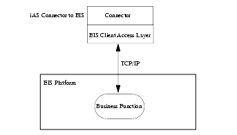
One or more iPlanet UIF enabled servers (iAS servers with iPlanet UIF installed) can communicate with the backend EIS. The following diagram shows the overview of the components between the server and the target machine:
Connector communicates with EIS using a connection. The connector uses an EIS specific client access layer to supply the connection. The connection protocol between this client protocol layer and EIS is EIS specific (usually TCP/IP, but in some cases another, for example CICS uses LU6). UIF maintains a connection pool for each EIS and each connection is reused for multiple application requests.
Depending on the specific EIS, establishing communication between the connector and EIS may require installing an extra component as the EIS host machine. For example, CICS requires a relay program. For more information about pooling, see Chapter 3 "Pooling Concepts".
Tools
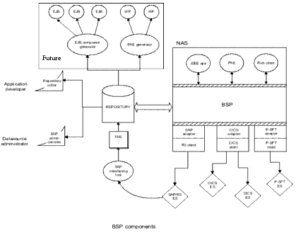
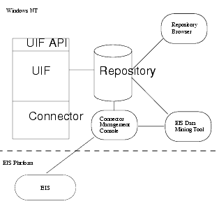
The following figure shows the tools used to configure iPlanet UIF:
The Repository Browser allows you to view the contents of the repository and to import and export XML files. Allows web application developers to discover EIS business functions available for execution.
The EIS Management Console allows you to browse or change the connector configuration and to monitor the EIS system status. Each connector has an connector specific Management Console.
The EIS Data Mining Tool is part of the Management Console. It allows you to determine the EIS system's available transactions and to load its meta information into the repository as FunctionObjects available for execution by a web application
User Roles and Tasks
Different skill sets are typically involved in setting up iPlanet UIF, they are as follows:
UIF Repository
UIF stores information in the Repository, which define the EIS business functions available to an iAS servlet or EJB. Repository data include metadata definitions that are one of two types:
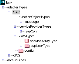
Connector types define connector specific characteristics, including the function object types and logical connection types supported (service provider types). This forms the basis for defining datasources of this connector type.
For information on how-to view the Repository, see Chapter 2 "The Repository Browser".Data sources define a logical data source, and represents a specific EIS instance (system). A datasource definition specifies the business functions available on a specific backend system; a data source is an connector type instantiation. The data source defines the actual functions available (function objects), the supported connections (service providers), and other information.
The following sections describe connector types, data sources, and their components.
Connector Types
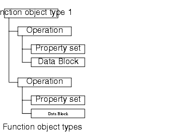
Connector type definitions correspond to each installed connector on iAS. It forms the basis of a data source definition in the repository. An connector type contains one or more function object types, a service provider type, and configuration information. A type definition is created when the connector is installed. It's contents are not modified and does not contain information of direct relevance to the user.
Data Sources
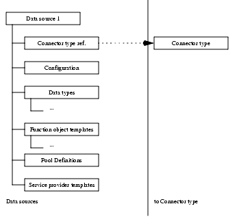
A data source represents a single EIS instance and defines the business functions available for execution on that data source. For example, an organization might have two systems or subsystems, one for personnel (human resources) and one for accounting. You can choose to represent each as a different data source.A programmer writing a servlet or EJB uses a data source definition in the Respository to determine the function objects and service provider available on a particular data source system. The following diagram shows the data source's basic components.
The following table shows the relationship between function objects and service providers:
A data source consists of an data source configuration information, data type definitions, service provider definitions, function object definitions, pool definitions, and user mapping information. The following sections describe these components in more detail.
Data Source Configuration Information
These are backend specific configuration settings, to be interpreted and used by the connector to control its interaction with a specific backend system. A datasource is essentially an instance of a specific connector type. The values of these specific settings control the connector's interaction with the EIS instance corresponding to this datasource.
Data Type Definitions
These are data type definitions which the metadata service uses to instantiate data objects. All information between the application and the connector is passed using dataObjects. These data type definitions typically represent structured backend datatypes, and are typically mined from backend metadata. Each specific backend system may have it's own set of datatypes, which is why they are associated with the datasource and not the connector type. These datatypes may represent param blocks, messages, events, etc. - depending on the specific backend system. The connector is responsible for marshalling/unmarshalling data objects to/from backend formats.
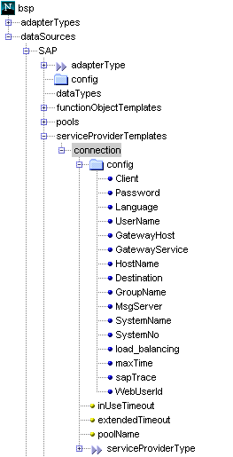
Service Provider Definitions
A service provider represents a connection to a backend EIS system. It contains configuration information, required to create a connection. For example it may define, host, port, username, and password. A service provider type may also specify additional information required to open or manage a connection.These are definitions of logical connections to the backend. The definition includes default backend specific configuration settings, whether the connection is to be pooled or not, and if so which pool. If pooled, what is the duration of the serviceProvider connection binding. Also defined are binding timeouts, and thread handoff settings.
Function Object Definitions
These are the logical definitions of business functions available on the target datasource. A specific functionObject usually represents (targets) a specific storedProc, prepared query, BAPI, RFC, psft message, MQseries message, CICS txn etc., depending on the backend type. Each backend system may have it's own set of business functions, which is why they are associated with the datasource and not the connector type.Function objects are created in the repository using a data mining tool supplied with each connector. The data mining tool creates a definition of the unique business function in XML. The XML file is then loaded into the repository as an FunctionObject.
Operations
The functionObject itself exposes one or more named operations. For example, an MQ message functionObject may expose three operations: SEND, POLL, RECEIVE. However, most systems would not need more than one (default) operation. Each operation has an associated propertySet and dataBlock.Each operation has a property set and data block associated with it, as follows:
dataBlock - a data object which encapsulates all inputs and outputs of this operation's execution. This object can have default/initial values. The connector is responsible for marshalling/unmarshalling the data object contents to/from backend formats.
propertySet - a data object whose value settings target this operation's execution to a specific backend business function. For example, dbName, storedProc name, BAPI name, Peoplesoft message identifier, program name, queue name, etc. The settings also control the operation execution.
Property Sets
The propertySet is a data object used to target a specific backend business function. For example, dbName, storedProc name, BAPI name, peopleSoft message identifier, program name, queue name, target host/port/URL etc. The connector uses the contents of the propertySet to target a specific backend business function.A property set is used to describe the various operational parameters. For example, an iPlanet UIF property set may specify the target program name and other information which controls the execution of this operation
Data Blocks
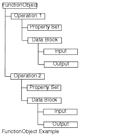
The dataBlock is a data object used for passing input/output between the application and backend. The connector is responsible for marshalling/unmarshalling dataBlocks to/from backend formats. Therefore, a functionObject targeting a specific business method has its own specific associated dataBlock type.A data block describes each business logic program's input and output parameters. In UIF, each data block two child nodes, input and output. The following diagram shows a target node with its input and output nodes.
FunctionObject Example
A function object template is a function object instances. A function object template contains a data block definition and a property set whose values define access to the EIS target transaction. data block represents the operation's parameter block and holds the input/output information operation execution.
dosearch: a named functionobject, representing a specific backend business function which accepts an account number as input and returns activity details as output. Application points to this and creates a runtime functionobject instance. When the execute method is called on this object, the connector executes the target backend business function.
The following diagram illustrates a function object template.
The following sections describe function objects, property sets, and data blocks.
Pool Definitions
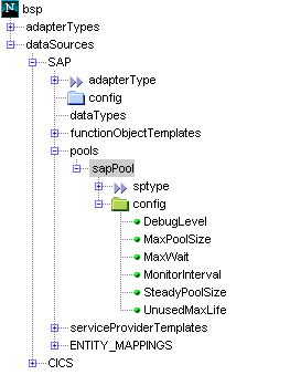
These are definitions of named connections (Service Provider) pools and their controlling attributes. A data source may define several connection pools. Usually, there is just a single pool. Each service provider defines which pool it pools in. Each defined pool is controlled by a pool configuration block, which contains:For more information about pooling, see Chapter 3 "Pooling Concepts". The following diagram shows the relationship between a service provider and the pool configuration information.
User Mapping Information
These are definitions of user mapping tables from web domain to backend domain, for a specific backend system. The contents of the user mapping tables are managed via the connector management console.
Management Console
The management console is used to view and change an EIS configuration. The Management Console allows you to convert native files to XML files, load files into the repository, and edit files. Each connector has a specific Management Console. However, all Management Consoles provide the following functionality:
Create a new data source
For connector specific Management Console information refer to your iPlanet Connector Administration Guide.Configure a data source, for example, connectivity options to the specific EIS instance
Development Strategy
After installing iPlanet UIF on both the iAS server and the target, you are ready to develop a servlet or EJB to invokes a target based transaction. Follow these recommended steps:
Run the data mining tool from the Management Console to create repository entries for function objects which you need to execute. For more information on the Management Console, refer to your Connector documentation.
You are now ready to execute your servlet or EJB within your iAS-based application.Function objects are imported by the Management Console.
In the Repository Browser select the datasource and, view the:
Service Provider definition to figure out what are the configuration attributes to be set in order to establish a connection
Function Object definition to figure out:
what (if any) are the property set attributes to be set
what inputs are expected in the data block
what outputs are defined in the data block
Write your servlet or EJB code to make use of the UIF API. For information about the methods to call, see Chapter 4 "Programming Concepts" For information about the UIF API, see Chapter 5 "API Reference". Follow the same strategy for writing your servlet or EJB that you ordinarily use for iAB- or iAS-based applications.
- to pass in parameters to the UIF API methods you are calling. For information about using the Repository Browser, see Using the Repository Browser.
After you write and test your servlet or EJB, use the iAS Deployment Manager to deploy your application. In addition, you must explicitly deploy the repository contents by exporting its contents to XML and importing the XML file on the deployment machine. For more information about exporting and importing XML files, see Using the Repository Browser. For information about iAS deployment, see the iPlanet Application Server Deployment Guide.
Previous Contents Index DocHome Next
Copyright © 2000 Sun Microsystems, Inc. Some preexisting portions Copyright © 2000 Netscape Communications Corp. All rights reserved.
Last Updated June 08, 2000
