| A P P E N D I X B |
|
Using Standalone JBOD Arrays |
A single Sun StorEdge 3510 FC JBOD array can be connected directly to certain Solaris operating system hosts. The supported configurations differ substantially from the use of Sun StorEdge 3510 FC expansion units connected to Sun StorEdge 3510 FC RAID arrays. This appendix describes the usage of Sun StorEdge 3510 FC JBOD arrays.
The topics covered in this appendix are:
Sun StorEdge 3510 FC JBOD arrays can be attached directly to a single Sun host computer using either single-port or dual-port configurations. Refer to Single-Port Connections to Sun StorEdge 3510 FC JBOD Arrays and Dual-Port Connections to Sun StorEdge 3510 FC JBOD Arrays for more information.
The Sun StorEdge 3510 FC JBOD array can be used with currently released versions of the Solaris 8 operating system and the Solaris 9 operating system.
TABLE B-1 lists the Sun systems that are supported for the Sun StorEdge 3510 FC JBOD array. The table also shows the connection methods supported for each of the supported Sun systems.
Supported HBAs include (X)6767A 2 Gbit PCI Single FC HBA and X)6768A 2 Gbit PCI Dual FC HBA.
Limitations affecting the Sun StorEdge 3510 FC Array are listed below:
Refer to the "Monitoring JBODs" appendix in the Sun StorEdge 3000 Family CLI User's Guide for information about using these commands.
The following software management tools are provided on the Sun StorEdge 3000 Family Professional Storage Manager CD, provided with your array. The Sun StorEdge 3000 Family Documentation CD provides the related user guides.
For details on how to install Sun StorEdge Configuration Service, Sun StorEdge Diagnostic Reporter, or the Sun StorEdge CLI software, refer to the Sun StorEdge 3000 Family Software Installation Manual.
Sun StorEdge Configuration Service supports the Sun StorEdge 3310 SCSI array and Sun StorEdge 3510 FC array. It also supports, to a limited degree, standalone JBOD arrays. Since standalone JBOD arrays do not have a RAID controller or RAID controller firmware to manage the disks, this software support for JBODs is limited to the following functions:
Refer to the "Monitoring JBODs" appendix in the Sun StorEdge 3000 Family Configuration Service User's Guide for information about using these functions with JBOD arrays.
Use JBOD support only when you have a JBOD array connected directly to a host. This enables you to monitor peripheral device condition and events.
To monitor peripheral device condition and events of a Sun StorEdge FC JBOD array or Sun StorEdge SCSI JBOD array from the SSCS Console, you first need to enable JBOD support.
1. Select View  Agent Options Management.
The Agent Options Management window is displayed.
2. Select the Enable JBOD Support check box.
3. To immediately display the JBOD array in the main window, you need to probe for new inventory. Select View  View Server and click Probe.
The JBOD array is displayed in the main window.
In a single-bus configuration, both ports of the JBOD array are connected to one HBA on the server, as shown in the following example.
In a dual-bus configuration, each port is connected to its own HBA, as shown in the following example.
Sun StorEdge Diagnostic Reporter supports standalone JBOD arrays. However, triggered event notification is limited to environmental failures and hard drive failures.
The Sun StorEdge CLI supports JBOD arrays. However, because JBOD arrays do not have a RAID controller or RAID controller firmware to manage the disks, this CLI support is limited to the following sccli commands:
Refer to the "Monitoring JBODs" appendix in the Sun StorEdge 3000 Family CLI User's Guide for information about using these commands.
When a Sun StorEdge 3510 FC JBOD array is directly attached to a host, unique, hard-assigned loop IDs are assigned to each drive in the JBOD array. A loop ID is the decimal version of an AL_PA. The lowest number loop ID is the lowest priority address on the loop.
On the left front side of a Sun StorEdge 3510 FC JBOD array, underneath the left chassis ear, an ID switch is used to set loop IDs for the disk drives to different ranges of values.
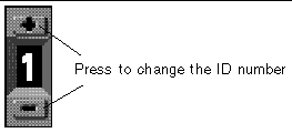
By default, the ID switch on all Sun StorEdge 3510 FC JBOD arrays is set to 0 so the range of IDs is automatically 0 to 11 for 12 drives (the IDs 12-15 are ignored). You can leave the ID switch set to 0, or set it for whichever range of IDs you prefer.
The ID switch offers eight ID ranges. Each set contains 16 IDs (the last 4 IDs in each range are ignored). These ranges are shown in TABLE B-2.
Follow these steps if you want to change your ID switch setting:
1. Remove the bezel (the front faceplate).
See Replacing the Front Bezel and Ear Caps for step-by-step instructions for removing and replacing the front bezel and ear caps.
2. Remove the left plastic ear cap from the front of the chassis.
3. Use the buttons to change the ID number.
4. Reattach the plastic ear cap and the bezel onto the front of the chassis.
You can connect a Sun StorEdge 3510 FC JBOD array directly to a host server. Use your standard host system disk management utilities for all disk management of disks in a Sun StorEdge 3510 FC JBOD array, such as partitioning and formatting. Refer to your host system documentation for more information about disk management.
There are two ways to verify that you have a Sun StorEdge 3510 FC JBOD array (or expansion unit) rather than a Sun StorEdge 3510 FC RAID array:
3510 AC JBOD (alternating current model) or 3510 DC JBOD (direct current model).
You can connect a Sun StorEdge 3510 FC JBOD array to an FC port, a port on a single-port HBA, or a single port on a dual-port HBA.
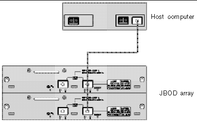
FIGURE B-2 shows an example of a Sun StorEdge 3510 FC JBOD array with 12 drives connected to a host computer over a single loop to a single FC port. In this example, the port is one of a pair of ports on a dual-port HBA.
In this example, if the loop ID switch is set to 0, the format command shows 12 drives on this loop, ranging from c1t0d0 to c1t11d0.
The drive identifiers are arranged in four columns of three drives each to reflect the physical location of these drives in the array. They correspond to the locations of Disk 1 through Disk 12 as shown in FIGURE B-5.
You can also connect a Sun StorEdge 3510 FC JBOD array to both ports on a dual-port HBA, ports on two single-port HBAs, or a port on a single-port HBA and a single port on a dual-port HBA.
Use host-based multipathing software such as VERITAS DMP 3.2 or 3.5 software to manage Sun StorEdge 3510 FC JBOD arrays connected to a host over more than one loop. Multipathing software provides full services on multiple paths between the server and the storage system.
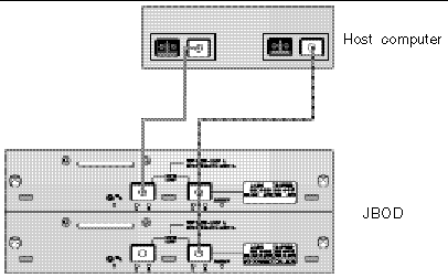
FIGURE B-3 shows an example of a Sun StorEdge 3510 FC JBOD array with 12 drives connected to a host computer over two loops to two FC ports. In this example both ports are on dual-port HBAs.
When you connect your Sun StorEdge 3510 FC JBOD array to a host over two loops, the format command shows 24 drives--12 on each loop--because the host sees a device entry for each path. If the loop switch ID is set to 0, these drives are identified as ranging from c1t0d0 to c1t11d0 and from c2t0d0 to c2t11d0, as shown in TABLE B-4. However there are, of course, still only 12 physical drives in the JBOD array. These drives are arranged in four columns of three drives each, as shown in TABLE B-3 and FIGURE B-5.

|
Caution - Be careful not to mount the same drive twice if you are not using multipathing software. |
Sun StorEdge 3510 FC JBOD arrays use SFP connectors to attach to Fibre Channel ports on your host computer. You might need to move or add one or more SFP connectors to your Sun StorEdge 3510 FC JBOD array to connect it to your host computer.
For more information about SFPs, refer to the Sun StorEdge 3000 Family Installation, Operation, and Service Manual for the Sun StorEdge 3510 FC Array.
Use fiber-optic cables to connect one or two HBA ports on the host computer to the Sun StorEdge 3510 FC JBOD array, as shown in the previous examples.
1. Connect a fiber-optic cable to an HBA.
2. Set your loop IDs using the ID switch on the JBOD array.
3. Connect the SFP connector at the other end of each of these fiber-optic cables to host channel SFP connectors on the back of the JBOD array.
4. Power up the equipment in the following order, so that the host computer discovers all connected arrays:
a. Sun StorEdge 3510 FC JBOD arrays
5. Use your host system disk management utilities to prepare the disks in the Sun StorEdge 3510 FC JBOD array for use.
Refer to your host system documentation for more information about disk management utilities available to you.
For Sun StorEdge 3510 FC JBOD arrays, use JBOD support only when you have a JBOD array connected directly to a host. This enables you to monitor peripheral device condition and events. If you have an expansion unit connected to a RAID array, the RAID controllers monitor the expansion unit's condition and events for you.
To monitor peripheral device condition and events of a Sun StorEdge 3510 FC JBOD array from the Sun StorEdge Configuration Service console, you first need to enable JBOD support.
1. Choose View  Agent Options Management.
The Agent Options Management window is displayed.
2. Select the Enable JBOD Support checkbox.
3. To immediately display the JBOD array in the main window, you need to probe for new inventory. Choose View  View Server and click Probe.
The JBOD array is displayed in the main window.
In a single-bus configuration, both ports of the JBOD array are connected to one HBA on the server, as shown in the following example:.
In a dual-bus configuration, each port is connected to its own HBA, as shown in the following example:
Replacing a disk drive is a straightforward operation that involves first removing the defective disk drive and then installing a replacement drive.
The drive module is hot-swappable; you can replace it while the array is powered on. To replace a disk drive module, first follow the procedure for removing a disk drive and then follow the procedure for installing a new disk drive.
|
Note - If you are removing a disk drive that you do not intend to replace, install an air management sled in its place. See Installing an Air Management Sled for more information. |
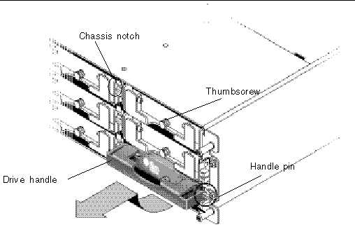
To remove a disk drive from an array, perform the following steps.
1. Perform any host software operations necessary to take the disk offline.
2. Unlock the locks with the provided key, and gently pull the plastic front bezel away from the front of the unit so that it drops down and is supported by the two hinged brackets on the sides.
3. Turn the thumbscrew counterclockwise several full turns until the thumbscrew and drive handle are loosened.
4. Gently pull the drive handle upward.
5. Slide the drive module out of the array.
To install a disk drive in an array, perform the following steps.
1. Gently slide the drive module into the drive slot until the handle pins slip into the chassis notch.
2. Lower the disk drive handle until it is vertical.
3. Press and hold the drive handle in while you press the thumbscrew in until it engages the threads.
4. Turn the thumbscrew clockwise until it is finger-tight.
|
Note - To ensure that a thumbscrew is finger-tight, tighten it with a screwdriver and then loosen the thumbscrew counterclockwise a quarter-turn. |
5. Push the plastic front bezel onto the front of the unit until it is seated firmly, and use the key to lock the locks.
6. Perform any operations your host software requires to recognize the new drive and bring it under software control.
The front of an air management sled looks similar to a disk drive module, but the air management sled is an empty box used to maintain optimum airflow in a chassis.
If you have removed a disk drive and do not intend to replace it, insert an air management sled to maintain the optimum airflow inside the chassis. You can install the air management sled by using the same procedure as Installing a New Disk Drive, except that no software operations are necessary.
For instructions on how to download firmware to disk drives in a JBOD directly attached to a host, refer to the README file in the patch that contains the firmware.
This section describes the meaning of front panel and back panel LEDs you can use to determine the status of the operation of all drives and modules.
It can be useful to power on an array before it is connected to a host. If a Sun StorEdge 3510 FC JBOD array is powered on and not connected to a server, the LED activity shown in the following table is visible.
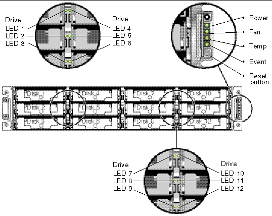
The drive LEDs are located between the rows of drives on the front panel, as shown in FIGURE B-5.
The system operation LEDs and Reset button are located on the right ear of the chassis, as shown in FIGURE B-6. Use a paperclip to push the Reset button to silence a failed component alarm. See Silencing Audible Alarms for more information about silencing audible alarms.
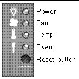
TABLE B-6 shows the JBOD array's front panel LEDs and their definitions.
The back panel LED colors indicate the conditions described in the following figures and tables.
|
Note - Although an amber light on the back panel often indicates a faulty component, a steady amber light on the Ethernet Link LED indicates normal Ethernet activity. See TABLE B-7 for more information. |
FIGURE B-7 shows the I/O module and its LEDs.

The following table shows the I/O module LEDs and their color definitions.
|
Note - An SFP Link Status (L) LED is off if there is no connection, or a failed connection, to this SFP. |
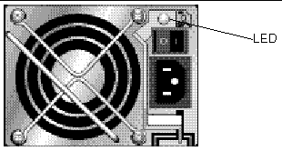
The following figure shows the AC power supply and fan module.
The following figure shows the DC power supply and fan module.
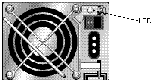
TABLE B-8 shows the color definitions for the power supply LED.
This section describes troubleshooting procedures and error messages you can use to isolate configuration and hardware problems. For additional troubleshooting information refer to the "Troubleshooting Your Array" chapter in the Sun StorEdge 3000 Family Installation, Operation, and Service Manual for the Sun StorEdge 3510 FC Array.
Follow this sequence of general steps to isolate software and configuration issues.
1. Look for storage-related messages in /var/adm/messages and identify any suspect Sun StorEdge 3510 FC JBOD arrays and fibre loops.
2. Check your Sun StorEdge Configuration Service console for alerts or messages.
3. Check revisions of software package, patches, and hardware.
4. Verify correct device file paths.
5. Check any related software, configuration, or startup files for recent changes.
Search SunSolve Online for any known related bugs and problems at: http://sunsolve.Sun.COM
When a problem is not otherwise reproducible, suspect hardware might need to be replaced. Always make only one change at a time and carefully monitor results. When possible, it is best to restore the original hardware before replacing another part to eliminate the introduction of additional unknown problem sources.
After hardware replacement, a problem can usually be considered solved if it does not resurface during a period equal to twice its original frequency of occurrence. For example, if a problem was occurring once a week on average before a potential fix was made, running two weeks without seeing the problem again suggests a successful fix took place.
Troubleshooting hardware problems is usually accomplished by an FRU isolation sequence that uses the process of elimination. Set up a minimal configuration that shows the problem and then replace elements in this order, testing after each replacement until the problem is solved:
Often you can also find out what does cause a hardware problem by determining the elements that do not cause it. Start out by testing the smallest configuration that does work, and then keep adding components until a failure is detected.
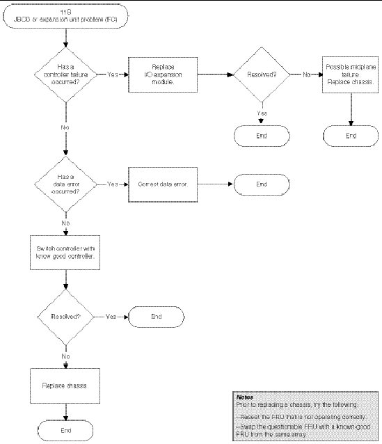
To view error messages reported by JBODs or expansion units, use any of the following:
For more information about replacing the chassis, I/O module, or controller, refer to the Sun StorEdge 3000 Family FRU Installation Guide for 2U Arrays.

|
Caution - To prevent any possible data loss, back up the chassis data onto another storage device prior to replacing a disk drive. |
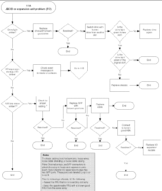
Before you begin troubleshooting JBODs or expansion units, check the cables that connect the host to the JBOD or expansion unit. Look for bent pins, loose wires, loose cable shields, loose cable casing, and any FC cables with 90 degree or more bends in them. If you find any of these problems, replace the cable.
The FIGURE B-10 flowchart provides troubleshooting procedures specifically for JBODs and expansion units. For additional troubleshooting flowcharts, see and .
If you have an FC JBOD and want to convert it to an FC RAID array, refer to the Sun StorEdge 3000 Family FRU Installation Guide for instructions.
Copyright © 2004, Sun Microsystems, Inc. All rights reserved.