| C H A P T E R 8 |
|
Troubleshooting Your Array |
This chapter covers the following maintenance and troubleshooting topics:
For more troubleshooting tips, refer to the Sun StorEdge 3510 FC Release Notes at:
http://www.sun.com/products-n-solutions/hardware/docs/Network_Storage_Solutions/Workgroup/3510

|
Caution - When mapping partitions to LUN IDs, there must be a LUN 0. Otherwise, none of the LUNs will be visible. |
By default, all RAID arrays are preconfigured with one or two logical drives. For a logical drive to be visible to the host server, its partitions must be mapped to host LUNs. For mapping details, refer to Mapping Logical Drive Partitions to Host LUNs. Check that you have completed this task.
To make the mapped LUNs visible to a specific host, perform any steps required for your operating system or environment. For host-specific information about different operating environments and operating systems, see:
Controller failure symptoms are as follows:
A "Redundant Controller Failure Detected" alert message is displayed and written to the event log.
If one controller in the redundant controller configuration fails, the surviving controller takes over for the failed controller until it is replaced.
A failed controller is managed by the surviving controller, which disables and disconnects from its counterpart while gaining access to all the signal paths. The surviving controller then manages the ensuing event notifications and takes over all processes. It is always the primary controller regardless of its original status, and any replacement controller afterward assumes the role of the secondary controller.
The failover and failback processes are completely transparent to the host.
Controllers are hot-swappable if you are using a redundant configuration, and replacing a failed unit takes only a few minutes. Since the I/O connections are on the controllers, you might experience some unavailability between the times when the failed controller is removed and a new one is installed in its place.
To maintain your redundant controller configuration, replace the failed controller as soon as possible. For details, refer to Sun StorEdge 3000 Family FRU Installation Guide.
This section describes automatic and manual procedures for rebuilding logical drives.
|
Note - As disks fail and are replaced, the rebuild process regenerates the data and parity information that was on the failed disk. However, the NVRAM configuration file that was present on the disk is not re-created. After the rebuild process is complete, restore your configuration as described in Restoring Your Configuration (NVRAM) From a File. |
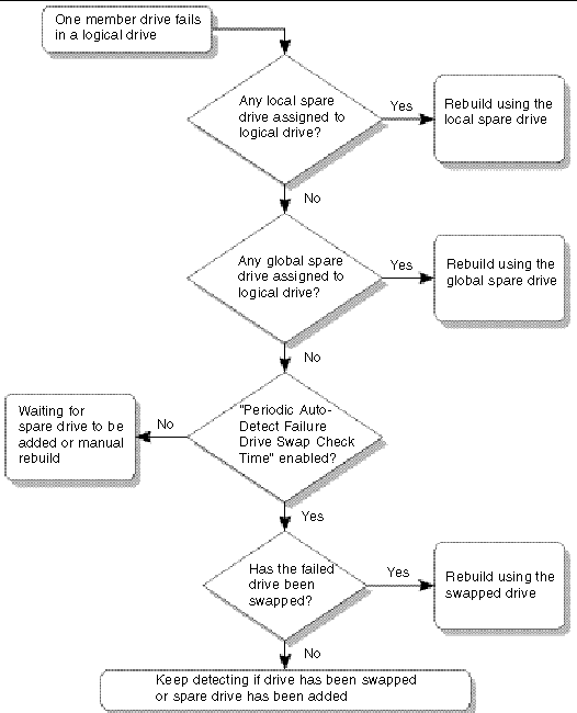
Rebuild with Spare. When a member drive in a logical drive fails, the controller first examines whether there is a local spare drive assigned to this logical drive. If yes, it automatically starts to rebuild the data of the failed disk to it.
If there is no local spare available, the controller searches for a global spare. If there is a global spare, it automatically uses it to rebuild the logical drive.
Failed Drive Swap Detect. If neither a local spare drive nor a global spare drive is available, and the "Periodic Auto-Detect Failure Drive Swap Check Time" is disabled, the controller does not attempt to rebuild unless you apply a forced-manual rebuild.
To enable this feature, follow these steps:
1. Choose "view and edit Configuration parameters  Drive-side SCSI Parameters
  Periodic Auto-Detect Failure Drive Swap Check Time."
When the "Periodic Auto-Detect Failure Drive Swap Check Time" is enabled (that is, when a check time interval has been selected), the controller detects whether the failed drive has been swapped by checking the failed drive's channel/ID. Once the failed drive has been swapped, the rebuild begins immediately.
|
Note - This feature requires system resources and can impact performance. |
If the failed drive is not swapped but a local spare is added to the logical drive, the rebuild begins with the spare.
For a flowchart of automatic rebuild, see FIGURE 8-1.
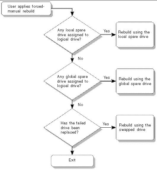
When a user applies forced-manual rebuild, the controller first examines whether there is any local spare assigned to the logical drive. If yes, it automatically starts to rebuild.
If there is no local spare available, the controller searches for a global spare. If there is a global spare, the logical drive rebuild begins. See FIGURE 8-2.
If neither local spare nor global spare is available, the controller examines the channel and ID of the failed drive. After the failed drive has been replaced by a healthy one, the logical drive rebuild begins on the new drive. If there is no drive available for rebuilding, the controller does not attempt to rebuild until the user applies another forced manual rebuild.
RAID 1+0 allows multiple-drive failure and concurrent multiple-drive rebuilds. Drives newly swapped must be scanned and set as local spares. These drives are rebuilt at the same time; you do not need to repeat the rebuilding process for each drive.
If there is a failed drive in the RAID 5 logical drive, replace the failed drive with a new drive to keep the logical drive working.
|
Note - The following procedure works only if there is no I/O activity. |
To find a failed drive, identify a single drive, or test all drive activity LEDs, you can flash the LEDs of any or all drives in an array. Since a defective drive does not light up, this provides a good way to visually identify a failed drive before replacing it.
1. Choose "view and edit scsi Drives."
2. Select the drive you want to identify, and then press Return.
3. Choose "Identify scsi drive  flash All drives" to flash the activity LEDs of all of the drives in the drive channel.
The option to change the Flash Drive Time is displayed.
4. Change the duration if you want. Then press Return and choose Yes.
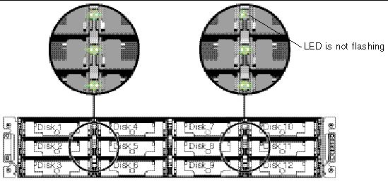
The read/write LED of a failed hard drive does not flash. The absence of a lit LED helps you locate and remove the failed drive.
In addition to flashing all drives, you can flash the read/write LED of only a selected drive or flash the LEDs of all drives except the selected drive, using steps similar to those outlined. These three drive-flashing menu options are described in the following sections.
When you choose this menu option, the read/write LED of the drive you select flashes for a configurable period of time from 1 to 999 seconds.
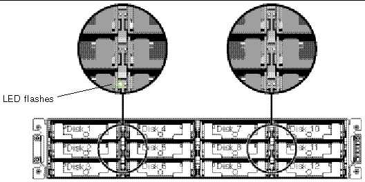
The "Flash All SCSI Drives" menu option flashes LEDs of all good drives but does not flash LEDs for any defective drives. In the illustration, there are no defective drives.
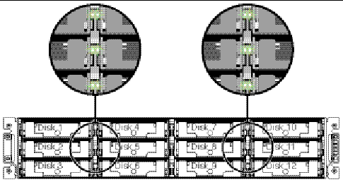
With this menu option, the read/write LEDs of all connected drives except the selected drive flashes for a configurable period of time from 1 to 999 seconds.
With a redundant RAID array system, your system is protected with the RAID parity drive and a global spare or spares.
In the extremely rare occurrence that two or more drives appear to fail at the same time, perform the following steps:
1. Discontinue all I/O activity immediately.
2. To cancel the beeping alarm, in the firmware Main Menu, choose "system Functions  Mute beeper."
See Section 7.2, Silencing Audible Alarms for more information about silencing audible alarms.
3. Physically check that all the drives are firmly seated in the array and that none have been partially or completely removed.
4. In the firmware Main Menu, choose "view and edit Logical drives," and look for:
Status: FAILED DRV (one failed drive)
Status: FATAL FAIL (two or more failed drives)
5. Highlight the logical drive, press Return, and choose "view scsi drives."
If two physical drives have a problem, one drive has a BAD status and one drive has a MISSING status. The MISSING status is a reminder that one of the drives might be a "false" failure. The status does not tell you which drive might be a false failure.
 Reset controller" and choose Yes to confirm.
7. Repeat Steps 4 and 5 to check the logical and drive status.
After resetting the controller, if there is a false bad drive, the array automatically starts rebuilding the failed RAID set.
If the array does not automatically start rebuilding the RAID set, check the status under "view and edit Logical drives."
a. Replace the failed drive. Refer to Sun StorEdge 3000 Family FRU Installation Guide for more information.
b. Delete the logical drive. Refer to the Sun StorEdge 3000 Family RAID Firmware User's Guide for more information.
c. Create a new logical drive. See Creating Logical Drives (Optional) for more information.
|
Note - As disks fail and are replaced, the rebuild process regenerates the data and parity information that was on the failed disk. However, the NVRAM configuration file that was present on the disk is not re-created. After the rebuild process is complete, restore your configuration as described in Restoring Your Configuration (NVRAM) From a File. |
For additional troubleshooting tips, refer to the Sun StorEdge 3510 FC Family Release Notes, located at:
http://www.sun.com/products-n-solutions/hardware/docs/Network_Storage_Solutions/Workgroup/3510
Monitoring temperature at different points within the array is one of the most important SES functions. High temperatures can cause significant damage if they go unnoticed. If you are alerted to out-of-limits temperatures by one of the SES sensors, choose "view and edit Peripheral devices  View Peripheral Device Status
  SES Device
  Temperature Sensors" to get information about the sensor reporting the condition.
There are a number of different sensors at key points within the enclosure. The following table shows the location of each of those sensors. The Element ID corresponds to the identifier shown when you choose "view and edit Peripheral devices  View Peripheral Device Status
  SES Device
  Temperature Sensors."
Using controller firmware menu options, you can view the status of SES components, including the pair of fans located in each fan and power supply module. A fan is identified by the SES Device menus as a cooling element.
To view the status of each fan, perform the following steps:
1. Choose "view and edit Peripheral devices  View Peripheral Device Status
  SES Device
  Cooling element."
2. Select one of the elements (element 0, 1, 2, or 3) and press Return.
Standard fan speeds are indicated by numbers 1 through 7, indicating speeds in the normal range of 4000 to 6000 RPM. The number 0 indicates that the fan has stopped.
If a fan fails and the Status field does not display the OK value, you must replace the fan and power supply module.
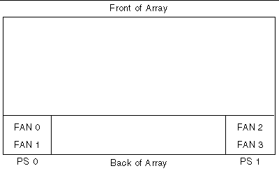
Cooling elements in the status table can be identified for replacement as shown in TABLE 8-2.
There are a number of interrelated drive-side SCSI parameters you can set using the "view and edit Configuration parameters" menu option. It is possible to encounter undesirable results if you experiment with these parameters, so it is good practice to only change parameters when you have good reason to do so. Refer to the "Viewing and Editing Configuration Parameters" chapter of the Sun StorEdge 3000 Family RAID Firmware User's Guide for cautions about particular parameter settings that should be avoided. In particular, do not set the "Periodic SAF-TE and SES Device Check Time" to less than one second, and do not set the "SCSI I/O Timeout" to anything less than 15 seconds, and preferably no less than the FC default of 30 seconds.
This section provides troubleshooting flowcharts to illustrate common troubleshooting methods.
The flowcharts included in this section are:
For the JBOD and expansion unit flowchart, refer to Troubleshooting Sun StorEdge 3510 FC JBOD Arrays.
For overview information about LEDs, see Chapter 6.
For more information about replacing each module, refer to the Sun StorEdge 3000 Family FRU Installation Guide for 2U Arrays.
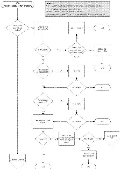
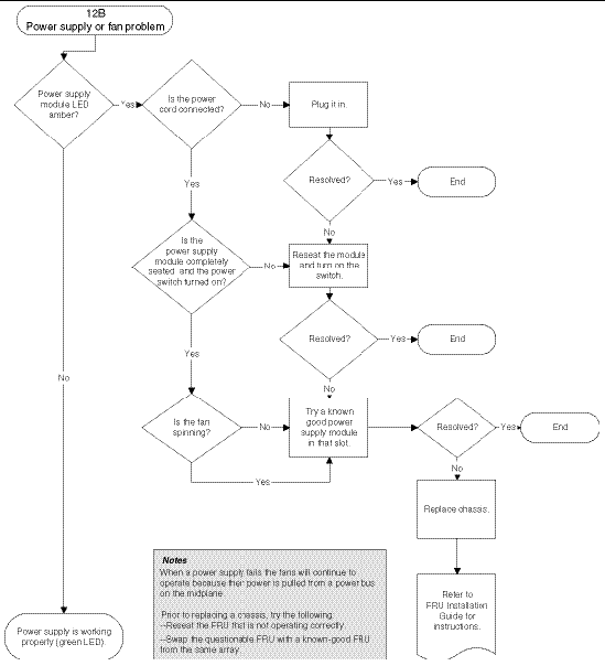
The following flowchart provides troubleshooting procedures for the power supply and fan module.
Before you perform the drive LED troubleshooting procedures, you might want to use the firmware application to identify a failed drive. See Identifying a Failed Drive for Replacement for more details.
For overview information about drive LEDs and how they work, see Front Panel LEDs.
You can check the physical drive parameters using the firmware application. From the firmware Main Menu, choose "view and edit scsi drives." For more information about the firmware application, refer to the Sun StorEdge 3000 Family RAID Firmware User's Guide for your array.

|
Caution - To prevent any possible data loss, back up the chassis data onto another storage device prior to replacing a disk drive. |
The following flowchart provides troubleshooting procedures for the FC drive LEDs.
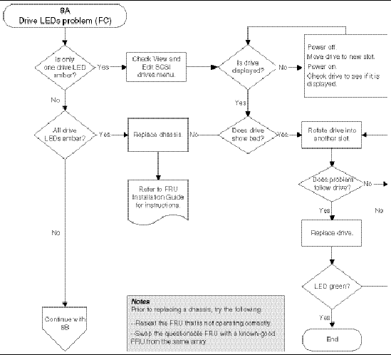
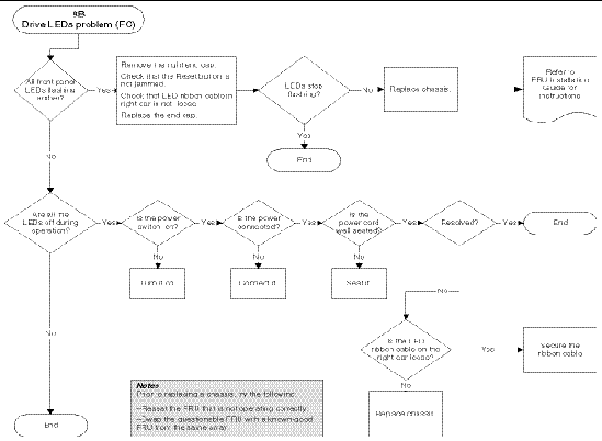
For more information about replacing the chassis and EMU module, refer to the Sun StorEdge 3000 Family FRU Installation Guide for 2U Arrays.
The following flowchart provides troubleshooting procedures for the FC front panel LEDs.
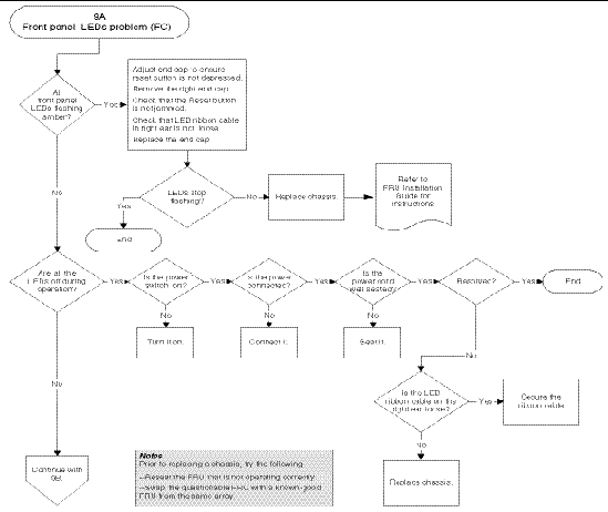
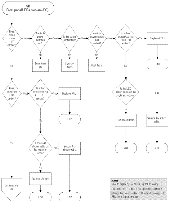
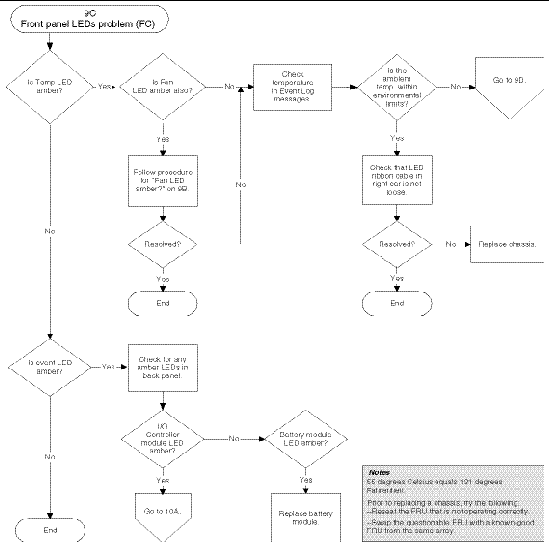
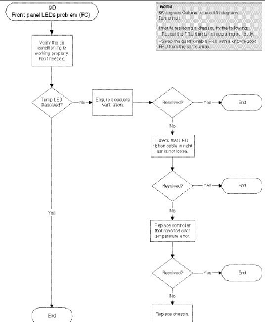
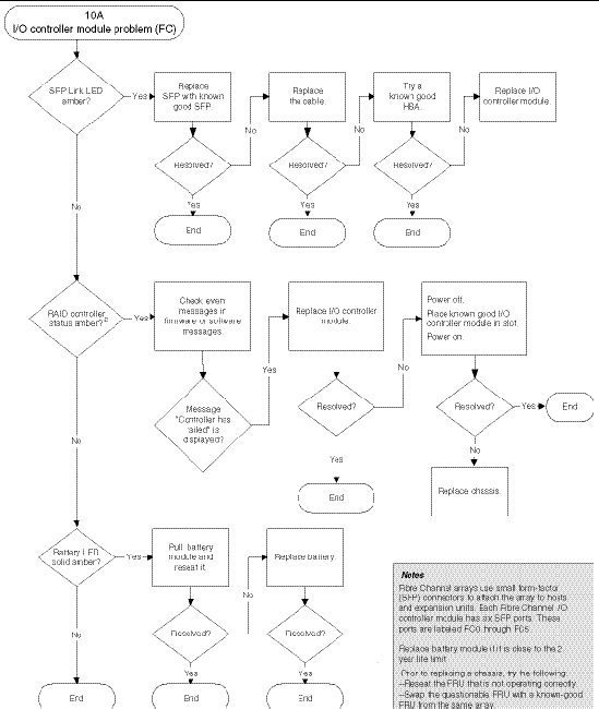
The following flowchart provides troubleshooting procedures for the I/O controller module.
To test that the LEDs work, using a paperclip, press and hold the Reset button for 5 seconds. All the LEDs should change from green to amber when you perform this test. Any LED that fails to light indicates a problem with the LED. When you release the Reset button, the LEDs return to their initial state. See Chassis Ear LEDs and Reset Button on Front Panel for more information.
To silence audible alarms that are caused by component failures, use a paperclip to push the Reset button. See Section 7.2, Silencing Audible Alarms for more information about silencing audible alarms.
An audible alarm indicates that either a component in the array has failed or a specific controller event has occurred. The cause of the alarm determines how you silence the alarm. See Section 7.2, Silencing Audible Alarms for more information about silencing audible alarm.
Copyright © 2004, Sun Microsystems, Inc. All rights reserved.