| Sun StorEdge 3000 Family Installation, Operation, and Service Manual
|
   
|
This chapter describes the front and back panel LEDs, which give the clear status of the operation of all drives and modules. Topics covered in this chapter are:
For troubleshooting flowcharts related to LEDs, refer to Troubleshooting Flowcharts.
6.1 LEDs When Array Is First Powered On
With the array powered up but not connected to a server, you should see the LED conditions described in TABLE 6-1.
TABLE 6-1 Front Panel LED Status When Array Is First Powered On
|
Drive LEDs
|
Solid green
|
|
Chassis ear LEDs
|
Solid green
|
6.2 Front Panel LEDs
The drive LEDs are located between the rows of drives on the front panel, as shown in FIGURE 6-1. The system operation LEDs are located on the right ear of the chassis.
FIGURE 6-1 Front Panel LEDs
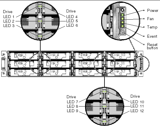
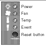
FIGURE 6-2 shows the front panel LEDs and the Reset button. Use a paperclip to push the Reset button to silence a failed component alarm. See Section 7.2, Silencing Audible Alarms for more information about silencing audible alarms.
FIGURE 6-2 Chassis Ear LEDs and Reset Button on Front Panel
The following table lists the front panel LEDs.
TABLE 6-2 Front Panel LEDs
|
LED
|
LED Color
|
Description
|
|
Drive
|
Solid green
|
Good: Drive power-up and spin-up OK.
|
|
Blinking green
|
Good: Drive activity.
|
|
Solid amber
|
Failed: Drive failure.
|
|
Power (Light bulb icon)
Monitors the DC output voltage within tolerance specification. Overcurrent protection shutting down any voltage output is also displayed.
Voltage thresholds:
+5 VDC +/-.25 VDC
+12 VDC +/-.6 VDC
Current thresholds:
+5 VDC 35A
+12 VDC 25A
|
Solid green
|
Good: Power supply good.
|
|
Solid amber
|
Failed: One or more output voltages out-of-range.
|
|
Fan (Fan icon)
Monitors the fan speed within nominal operational RPM specification of 5000 RPM.
|
Solid green
|
Good: Both fans rotating at 4000 RPM or higher.
|
|
Solid amber
|
Faulty/Failed: One or both fans rotating a less than 4000 RPM.
|
|
Temp (Thermometer icon)
Monitors the temperature level and indicates violations of internal temperature thresholds of 55C and 60C.
|
Solid green
|
Good: Under temperature threshold of 55C.
|
|
Solid amber
|
Failed: Temperature threshold equal to or over 55C.
|
|
Blinking amber
|
Failed: Temperature threshold equal to or over 60C. Blinking frequency of 4 Hz +/- 1 Hz.
|
|
Event (Caution icon)
Indicates any abnormal or failure event in the I/O board.
|
Solid green
|
Normal operation of I/O board.
|
|
Solid amber
|
Failed I/O board.
|
|
Blinking amber
|
Indicates that the version of the SES firmware or associated hardware PLD code on one controller does not match that on the other controller.
|
|
Note - To test that the LEDs work, using a paperclip, press and hold the Reset button for 5 seconds. All the LEDs should change from green to amber when you perform this test. Any LED that fails to light indicates a problem with the LED. When you release the Reset button, the LEDs return to their initial state.
|
6.2.1 Correcting SES or PLD Firmware Version Conflicts
From time to time, firmware upgrades are made available as patches that you can download from SunSolve Online, located at:
http://sunsolve.sun.com
Each patch applies to a particular piece of firmware, including the firmware programmed into SES and PLD chips included in your controller.
SunSolve has extensive search capabilities that can help you find these patches, as well as regular patch reports and alerts to let you know when firmware upgrades and other patches become available. In addition, SunSolve provides reports about bugs that have been fixed in patch updates.
Each patch includes an associated README text file that provides detailed instructions about how to download and install that patch. But, generally speaking, all firmware downloads follow the same steps:
- Locating the patch on SunSolve that contains the firmware upgrade you want
- Downloading the patch to a location on your network
- Using your array software (SSCS or sscli[1M]) or array firmware, in some cases, to "flash" the firmware to the device it updates
Refer to the release notes for your array for patch numbers of firmware and other patches available for your array at the time of release.
When you replace an I/O controller, the new controller might have a version of SES or PLD firmware different from the other controller in your array. If this mismatch occurs, when you install a controller you hear an audible alarm and see a blinking amber Event light.
To synchronize the SES firmware and hardware PLD versions, you need to download new SES firmware through Sun StorEdge Configuration Service software or the command-line interface (CLI).
If you have not installed this software, you need to install it from the software CD that shipped with your array. Refer to the Sun StorEdge 3000 Family Configuration Service User's Guide for your array to see instructions for downloading firmware for devices, or refer to the sccli(1M) man page for similar instructions using the CLI. Refer to the release notes for your array for instructions about where to obtain the firmware that you need to download.
When you open Sun StorEdge Configuration Service software or the CLI and connect to the array, an error message alerts you to the mismatched version problem.
6.3 Back Panel LEDs
The back panel LED colors indicate the conditions described in the following figures and tables.
|
Note - Although an amber light on the back panel often indicates a faulty component, a steady amber light on the Ethernet link LED indicates normal Ethernet activity. See TABLE 6-3 for more information.
|
6.3.1 I/O Controller Module LEDs
FIGURE 6-3 shows the I/O controller module and its LEDs on the back panel.
FIGURE 6-3 I/O Controller Module and Battery Module LEDs
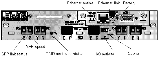
FIGURE 6-4 shows the I/O expansion module and its LEDs.
FIGURE 6-4 I/O Expansion Module for an Expansion Unit

The I/O controller module LEDs and their color definitions are shown in TABLE 6-3.
TABLE 6-3 I/O Controller Module and Battery Module LEDs
|
LED
|
Purpose
|
LED Color Definition
|
|
Battery
|
Status of battery
|
Solid green - Battery charged
Blinking green - Battery charging
Solid amber - Battery failed
|
|
Activity
|
I/O activity of host and disk ports
|
Off - Not busy (no I/O activity)
Blinking green - Busy (active I/O)
|
|
Cache
|
Status of memory cache
|
Off - Clean cache
Blinking green - Dirty cache; indicates if data in memory and is not written to disk yet
|
|
Ethernet link
(active controller)
|
Status of Ethernet link
|
Solid amber - Active link
Off - Inactive connection
|
|
Ethernet link
(inactive controller)
|
Status of Ethernet link
|
Off - Active connection on inactive controller or on active connection
|
|
Ethernet active
|
Status of Ethernet activity
|
Flashing green - Busy
|
|
RAID controller
|
Status of controller on I/O controller module
|
Blinking green - Good (primary controller)
Solid green - Good (secondary controller)
Solid amber - Failed RAID controller or I/O module
|
|
SFP link (L)
|
SFP link status
|
Solid green - Active good FC Connection
Off - Empty or failed FC connection
|
|
SFP speed (S)
|
SFP speed status
|
Solid green - 2 Gbit
Off - 1 Gbit
|
|
Note - The Sun StorEdge 3510 FC array's Ethernet link LED differs from that found on a Sun StorEdge 3310 SCSI array. A connected port's Ethernet link LED glows solid amber only on the active controller, because a FC port is considered active only if its controller is active. On an inactive controller, a port's Ethernet link LED is off whether it is connected or not. The absence of a solid amber light on a connected port's Ethernet link LED for a connected port indicates that this controller is not the active controller.
|
|
Note - An SFP link status (L) LED is off if there is no connection, or a failed connection, to this SFP.
|
|
Note - To test that the LEDs work, using a paperclip, press and hold the Reset button for 5 seconds. All the LEDs should change from green to amber when you perform this test. Any LED that fails to light indicates a problem with the LED. When you release the Reset button, the LEDs return to their initial state.
|
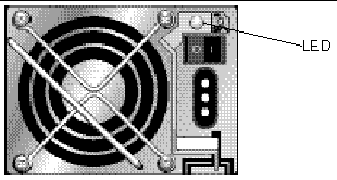
6.3.2 Power Supply and Fan Module LEDs
TABLE 6-4 Power Supply LEDs
|
Purpose
|
LED
|
LED Color Definition
|
|
Monitors the DC output voltage within tolerance specification. Overcurrent protection shutting down any voltage output is also displayed.
Voltage thresholds:
+5 VDC +/-.25 VDC
+12 VDC +/-.6 VDC
Current thresholds:
+5 VDC 35A
+12 VDC 25A
|
Solid green
Solid amber
|
Power supply and fans are good.
Failed: One or more output voltages out-of-range or fan speed is under 3150 RPM.
|
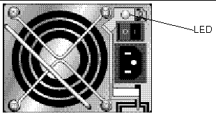
The following figure shows the AC power supply and fan module.
FIGURE 6-5 AC Power Supply and Fan Module
The following figure shows the DC power supply and fan module.
FIGURE 6-6 DC Power Supply and Fan Module
| Sun StorEdge 3000 Family Installation, Operation, and Service Manual
|
816-7300-15
|
   
|
Copyright © 2004, Sun Microsystems, Inc. All rights reserved.


 Online, located at:


