| Skip Navigation Links | |
| Exit Print View | |

|
Sun Blade X6275 M2 Server Module Service Manual |
About This Documentation (PDF and HTML)
Server Module and Components Overview
About the Sun Blade 6000 Modular System Chassis
Powering On and Off the Server Module
Preparation Procedures for Service and Operation
Preparing the Server for Service
Preparing the Server for Operation
Component Removal and Installation Procedures
Removing and Installing Flash Modules
Removing and Installing the Energy Storage Modules
Removing and Installing the Service Processor Board
Removing and Installing USB Flash Drives
Removing and Installing a CPU and Heatsink Assembly
How to Replace the Motherboard Assembly
Diagnostic and Maintenance Information and Procedures
Diagnosing Server Module Hardware Faults
BIOS Power-On Self-Test (POST) Codes
Server Module Maintenance Procedures and Information
BIOS Setup Utility Screens Overview
How to Configure the BIOS Using the BIOS Setup Utility
How to Display FRUID Information
How to Back Up FRU Information
Removing and Installing a Server Module Filler Panel
How to Remove a Server Module Filler Panel
How to Install the Server Module Filler Panel
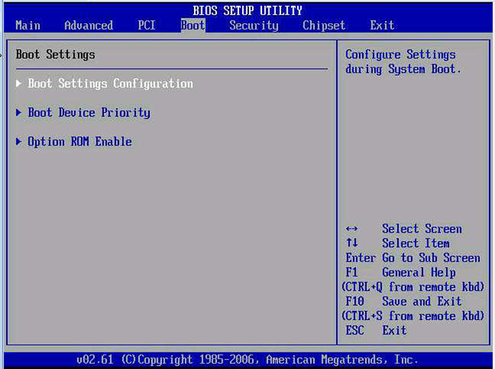
Figure 20 The Boot Settings Screen

The following table lists the configurable fields of the Boot screen.
|
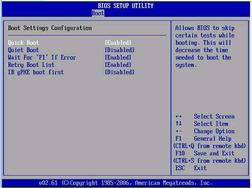
Figure 21 The Boot Settings Configuration Screen

The Boot Settings Configuration is a Boot submenu screen. The following table lists the configurable fields of the Boot Settings Configuration screen.
|
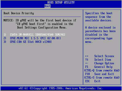
Figure 22 The Boot Device Priority Screen

The Boot Device Priority is a Boot submenu screen that allows you to prioritize the server's boot-capable devices by arranging them in a hierarchical boot order list.
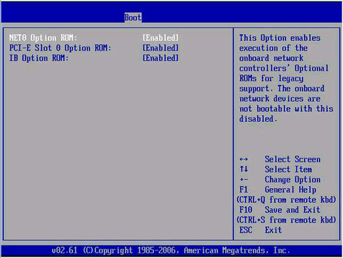
Figure 23 The Option ROM Enable Screen

The Option ROM Enable is a Boot submenu screen. The following table lists the configurable fields of the Option ROM Enable screen.
|