| Skip Navigation Links | |
| Exit Print View | |

|
Sun Blade X6275 M2 Server Module Product Documentation |
About This Documentation (PDF and HTML)
Hardware Installation and Product Notes
Overview of the Sun Blade X6275 M2 Server Module
Server Module Front Panel and Indicators
Installing and Powering On the Server Module
About Your Server Module Shipment
Finding the Serial Number and Accessing Warranty Support Information
How to Apply Full Power to a Server Module Node
How to Power Off a Server Module Node
Troubleshooting Server Power States
How to Display the ILOM IP Address Using the Web Interface
How to Display the ILOM IP Address Using the CLI
How to Log In to the ILOM Web Interface Using an Ethernet Connection
How to Log In to the ILOM CLI Using an Ethernet Connection
How to Log Into ILOM Using a Serial Connection
Configuring an ILOM IP Address
How to Configure a DHCP IP Address
How to Configure a Static IP Address
Accessing the Host Console Through ILOM
How to Connect to the Host's Serial Console Using the ILOM Command-Line Interface
How to Connect to the Host Console Using the ILOM Web Interface
Overview of the Sun Blade X6275 M2 Server Module Product Notes
System Software Release Features
Hardware, Firmware, and BIOS Issues
Installing the Oracle Solaris Operating System
Installing Red Hat Enterprise Linux
Installing the SLES Operating System
Introduction to Oracle VM Installation
Creating a PXE Installation Image for Oracle VM
Introduction to Windows Installation
Getting Started With Windows Server 2008 Installation
Installing the Windows Server 2008 R2 Operating System
Updating Critical Drivers and Installing Supplemental Software
Incorporating Device Drivers into a WIM Image for WDS
Administration, Diagnostics, and Service
Overview of the ILOM Supplement
Managing Power Usage and Monitoring Power Consumption
Configuring the Server Power Restore Policy
Switching the Default Serial Port Output Between SP and Host Console
Indicators, Sensors, and Traps
Introduction to Diagnostic Tools
U-Boot Diagnostic Startup Tests
Accessing the Pc-Check Diagnostics Utility on the Tools and Drivers CD/DVD
Server Module and Components Overview
Preparation Procedures for Service and Operation
Component Removal and Installation Procedures
Before You Begin
Perform all steps and fulfill all requirements in Installation Prerequisites.
When the chassis is powered-on, the fans are operating and the chassis OK/Power LED illuminates a steady-on green light. The OK/Power LEDs are located on both the front and back of the chassis. If the chassis is not powered on, or in a fault state, refer to your chassis documentation for information on how to remedy the issue.
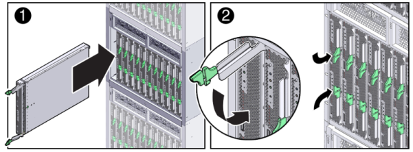
Pinch together the ends of the ejector arm handle to unlock it, rotate the lever out to the open position, and eject the filler panel.
Keep the filler panel for later use.
 | Caution - If you are not installing a server module into a slot, do not remove the slot filler panel. The slot filler panel is required to meet FCC standards for electromagnetic interference (EMI). Do not operate the chassis with empty slots for more than 60 seconds. Always insert a filler panel into an empty slot to reduce the possibility of chassis shutdown. |
The server module is now locked in the chassis.

After installing a server module into a powered-on chassis, each server module node SP automatically boots using standby power from the chassis power supplies. At this point, the chassis OK/Power LED should be steady-on green. The server module front panel indicators illuminate as follows:
After you plug in the server module, all four server module LEDs (on each node) blink three times. This indicates that the blade has been powered on and the SP boot process has begun.
The green OK/Power LEDs on each node blinks rapidly. This indicates that the node SP is booting (0.125 seconds on, 0.125 seconds off).
After each node SP completes its boot cycle, the green OK/Power LEDs on each node blinks briefly once every 3 seconds indicating that the node is in standby power mode.
Tip - For front panel LED information, see to the Server Module Front Panel and Indicators. For additional information about server module indicators, server module removal, power procedures, and front panel cable connections, refer to the Server Module and Components Overview in Sun Blade X6275 M2 Server Module Service Manual.
Next Steps