| Skip Navigation Links | |
| Exit Print View | |

|
Oracle Solaris Administration: Network Interfaces and Network Virtualization Oracle Solaris 11 Express 11/10 |
| Skip Navigation Links | |
| Exit Print View | |

|
Oracle Solaris Administration: Network Interfaces and Network Virtualization Oracle Solaris 11 Express 11/10 |
2. NWAM Configuration and Administration (Overview)
3. NWAM Profile Configuration (Tasks)
4. NWAM Profile Administration (Tasks)
5. About the NWAM Graphical User Interface
Part II Administering Single Interfaces
6. Overview of the Networking Stack
7. Datalink Configuration and Administration
8. Configuring an IP Interface
9. Configuring Wireless Interface Communications on Oracle Solaris
Part III Administering Interface Groups
11. Administering Link Aggregations
Back-to-Back Link Aggregations
Requirements for Link Aggregations
Flexible Names for Link Aggregations
Administering Link Aggregations (Task Map)
How to Create a Link Aggregation
How to Add a Link to an Aggregation
Part IV Network Virtualization and Resource Management
15. Introducing Network Virtualization and Resource Control (Overview)
16. Planning for Network Virtualization and Resource Control
17. Configuring Virtual Networks (Tasks)
18. Using Link Protection in Virtualized Environments
19. Managing Network Resources
Oracle Solaris supports the organization of network interfaces into link aggregations. A link aggregation consists of several interfaces on a system that are configured together as a single, logical unit. Link aggregation, also referred to as trunking, is defined in the IEEE 802.3ad Link Aggregation Standard.
The IEEE 802.3ad Link Aggregation Standard provides a method to combine the capacity of multiple full-duplex Ethernet links into a single logical link. This link aggregation group is then treated as though it were, in fact, a single link.
The following are features of link aggregations:
Increased bandwidth – The capacity of multiple links is combined into one logical link.
Automatic failover/failback – Traffic from a failed link is failed over to working links in the aggregation.
Load balancing – Both inbound and outbound traffic is distributed according to user selected load-balancing policies, such as source and destination MAC or IP addresses.
Support for redundancy – Two systems can be configured with parallel aggregations.
Improved administration – All interfaces are administered as a single unit.
Less drain on the network address pool – The entire aggregation can be assigned one IP address.
The basic link aggregation topology involves a single aggregation that contains a set of physical interfaces. You might use the basic link aggregation in the following situations:
For systems that run an application with distributed heavy traffic, you can dedicate an aggregation to that application's traffic.
For sites with limited IP address space that nevertheless require large amounts of bandwidth, you need only one IP address for a large aggregation of interfaces.
For sites that need to hide the existence of internal interfaces, the IP address of the aggregation hides its interfaces from external applications.
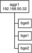
Figure 11-1 shows an aggregation for a server that hosts a popular web site. The site requires increased bandwidth for query traffic between Internet customers and the site's database server. For security purposes, the existence of the individual interfaces on the server must be hidden from external applications. The solution is the aggregation aggr1 with the IP address 192.168.50.32. This aggregation consists of three interfaces,bge0 through bge2. These interfaces are dedicated to sending out traffic in response to customer queries. The outgoing address on packet traffic from all the interfaces is the IP address of aggr1, 192.168.50.32.
Figure 11-1 Basic Link Aggregation Topology

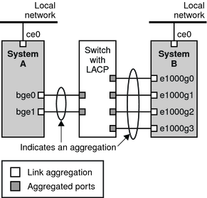
Figure 11-2 depicts a local network with two systems, and each system has an aggregation configured. The two systems are connected by a switch. If you need to run an aggregation through a switch, that switch must support aggregation technology. This type of configuration is particularly useful for high availability and redundant systems.
In the figure, System A has an aggregation that consists of two interfaces, bge0 and bge1. These interfaces are connected to the switch through aggregated ports. System B has an aggregation of four interfaces, e1000g0 through e1000g3. These interfaces are also connected to aggregated ports on the switch.
Figure 11-2 Link Aggregation Topology With a Switch

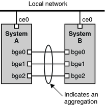
The back-to-back link aggregation topology involves two separate systems that are cabled directly to each other, as shown in the following figure. The systems run parallel aggregations.
Figure 11-3 Basic Back-to-Back Aggregation Topology

In this figure, device bge0 on System A is directly linked to bge0 on System B, and so on. In this way, Systems A and B can support redundancy and high availability, as well as high-speed communications between both systems. Each system also has interface ce0 configured for traffic flow within the local network.
The most common application for back-to-back link aggregations is mirrored database servers. Both servers need to be updated together and therefore require significant bandwidth, high-speed traffic flow, and reliability. The most common use of back-to-back link aggregations is in data centers.
If you plan to use a link aggregation, consider defining a policy for outgoing traffic. This policy can specify how you want packets to be distributed across the available links of an aggregation, thus establishing load balancing. The following are the possible layer specifiers and their significance for the aggregation policy:
L2 – Determines the outgoing link by hashing the MAC (L2) header of each packet
L3 – Determines the outgoing link by hashing the IP (L3) header of each packet
L4 – Determines the outgoing link by hashing the TCP, UDP, or other ULP (L4) header of each packet
Any combination of these policies is also valid. The default policy is L4. For more information, refer to the dladm(1M) man page.
If your aggregation topology involves connection through a switch, you must note whether the switch supports the link aggregation control protocol (LACP). If the switch supports LACP, you must configure LACP for the switch and the aggregation. However, you can define one of the following modes in which LACP is to operate:
Off mode – The default mode for aggregations. LACP packets, which are called LACPDUs are not generated.
Active mode – The system generates LACPDUs at regular intervals, which you can specify.
Passive mode – The system generates an LACPDU only when it receives an LACPDU from the switch. When both the aggregation and the switch are configured in passive mode, they cannot exchange LACPDUs.
See the dladm(1M) man page and the switch manufacturer's documentation for syntax information.
Your link aggregation configuration is bound by the following requirements:
You must use the dladm command to configure aggregations.
An interface that has been plumbed cannot become a member of an aggregation.
All interfaces in the aggregation must run at the same speed and in full-duplex mode.
You must set the value for MAC addresses to “true” in the EEPROM parameter local-mac-address? For instructions, refer to How to Ensure That the MAC Address of an Interface Is Unique.
Certain devices do not fulfill the requirement of the IEEE 802.3ad Link Aggregation Standard to support link state notification. This support must exist in order for a port to attach to an aggregation or to detach from an aggregation. Devices that do not support link state notification can be aggregated only by using the -f option of the dladm create-aggr command. For such devices, the link state is always reported as UP. For information about the use of the -f option, see How to Create a Link Aggregation.
Flexible names can be assigned to link aggregations. Any meaningful name can be assigned to a link aggregation. For more information about flexible or customized names, see Assigning Names to Datalinks. Previous Oracle Solaris releases identify a link aggregation by the value of a key that you assign to the aggregation. For an explanation of this method, see Overview of Link Aggregations. Although that method continues to be valid, preferably, you should use customized names to identify link aggregations.
Similar to all other datalink configurations, link aggregations are administered with the dladm command.
The following table links to procedures for administering link aggregations.
|
Note - Link aggregation only works on full-duplex, point-to-point links that operate at identical speeds. Make sure that the interfaces in your aggregation conform to this requirement.
If you are using a switch in your aggregation topology, make sure that you have done the following on the switch:
Configured the ports to be used as an aggregation
If the switch supports LACP, configured LACP in either active mode or passive mode
For more information, see How to Obtain Administrative Rights in System Administration Guide: Security Services.
# dladm show-link
For example, if the IP interface over the link is created, then remove the interface.
If a datalink is in use, then STATE field in the output of the dladm show-link will indicate that the link is up. Thus:
# dladm show-link
LINK     CLASS     MTU     STATE     BRIDGE   OVER
qfe3     phys      1500    up        --       --
If the datalink is in use, then the IP interface over that link will be included in the output of the ipadm show-if syntax. Thus:
# ipadm show-if
IFNAME     STATE    CURRENT       PERSISTENT
lo0        ok       -m46-v-----   ---
qfe3       down     bm46-------   -46
Note - Even if the output displays a down status, the datalink is still in use because an IP interface exists over the link.
# ipadm delete-if interface
where
Specifies the IP interface that is created over the link.
# dladm create-aggr [-f] -l link1 -l link2 [...] aggr
Forces the creation of the aggregation. Use this option when you are attempting to aggregate devices that do not support link state notification.
Specifies the datalinks that you want to aggregate.
Specifies the name that you want to assign to the aggregation.
# ipadm create-addr interface -T static -a IP-address addrobj
where interface should take the name of the aggregation and addrobj uses the naming convention interface/user-defined-string.
The aggregation's state should be UP.
# dladm show-aggr
Example 11-1 Creating a Link Aggregation
This example shows the commands that are used to create a link aggregation with two datalinks, subvideo0 and subvideo1. The configuration is persistent across system reboots.
# dladm show-link
LINK          CLASS     MTU     STATE   BRIDGE     OVER
subvideo0     phys      1500    up      --         ----
subvideo1     phys      1500    up46    --         ----

# ipadm delete-if subvideo0
# ipadm delete-if subvideo1
# dladm create-aggr -l subvideo0 -l subvideo1 video0
# ipadm create-addr -T static -a 10.8.57.50/24 video/v4
# dladm show-aggr
LINK      POLICY  ADDRPOLICY      LACPACTIVITY   LACPTIMER  FLAGS
video0    L4      auto            off            short      -----
When you display link information, the link aggregation is included in the list.
# dladm show-link
LINK          CLASS     MTU     STATE   BRIDGE     OVER
subvideo0     phys      1500    up      --         ----
subvideo1     phys      1500    up      --         ----
video0        aggr      1500    up      --         subvideo0, subvideo1
This procedure shows how to make the following changes to an aggregation definition:
Modifying the policy for the aggregation
Changing the mode for the aggregation
For more information, see How to Obtain Administrative Rights in System Administration Guide: Security Services.
# dladm modify-aggr -P policy-key aggr
Represents one or more of the policies L2, L3, and L4, as explained in Policies and Load Balancing.
Specifies the aggregation whose policy you want to modify.
# dladm modify-aggr -L LACP-mode -T timer-value aggr
Indicates the LACP mode in which the aggregation is to run. The values are active, passive, and off. If the switch runs LACP in passive mode, be sure to configure active mode for your aggregation.
Indicates the LACP timer value, either short or long.
Example 11-2 Modifying a Link Aggregation
This example shows how to modify the policy of aggregation video0 to L2 and then turn on active LACP mode.
# dladm modify-aggr -P L2 video0
# dladm modify-aggr -L active -T short video0
# dladm show-aggr
LINK      POLICY  ADDRPOLICY      LACPACTIVITY   LACPTIMER  FLAGS
video0    L2      auto            active         short      -----
For more information, see How to Obtain Administrative Rights in System Administration Guide: Security Services.
# ipadm delete-if interface
# dladm add-aggr -l link [-l link] [...] aggr
where link represents a datalink that you are adding to the aggregation.
For example, in the case of a configuration that is illustrated in Figure 11-3, you might need to add or modify cable connections and reconfigure switches to accommodate the additional datalinks. Refer to the switch documentation to perform any reconfiguration tasks on the switch.
Example 11-3 Adding a Link to an Aggregation
This example shows how to add a link to the aggregation video0.
# dladm show-link
LINK          CLASS     MTU     STATE     BRODGE   OVER
subvideo0     phys      1500    up        --       ----
subvideo1     phys      1500    up        --       ----
video0        aggr      1500    up        --       subvideo0, subvideo1
net3          phys      1500    unknown   --       ----

# ipadm delete-if video0
# dladm add-aggr -l net3 video0
# dladm show-link
LINK          CLASS     MTU     STATE     BRIDGE   OVER
subvideo0     phys      1500    up        --       ----
subvideo1     phys      1500    up        --       ----
video0        aggr      1500    up        --       subvideo0, subvideo1, net3
net3          phys      1500    up        --       ----
For more information, see How to Obtain Administrative Rights in System Administration Guide: Security Services.
# dladm remove-aggr -l link aggr-link
Example 11-4 Removing a Link From an Aggregation
This example shows how to remove a link from the aggregation video0.
dladm show-link
LINK          CLASS     MTU     STATE     OVER
subvideo0     phys      1500    up        --       ----
subvideo1     phys      1500    up        --       ----
video0        aggr      1500    up        --       subvideo0, subvideo1, net3
net3          phys      1500    up        --       ----

# dladm remove-aggr -l net3 video0
# dladm show-link
LINK          CLASS     MTU     STATE     BRIDGE   OVER
subvideo0     phys      1500    up        --       ----
subvideo1     phys      1500    up        --       ----
video0        aggr      1500    up        --       subvideo0, subvideo1
net3          phys      1500    unknown   --       ----
For more information, see How to Obtain Administrative Rights in System Administration Guide: Security Services.
# ipadm delete-if IP-aggr
where IP-aggr is the IP interface over the link aggregation.
# dladm delete-aggr aggr
Example 11-5 Deleting an Aggregation
This example deletes the aggregation video0. The deletion is persistent.
# ipadm delete-if video0
# dladm delete-aggr video0