| C H A P T E R 3 |
|
Installing Trays |
Use the procedures in this chapter to install controller and expansion trays in an industry-standard cabinet. The number of trays you need to install depends on your overall storage requirements. You can install a maximum of four trays, one controller tray and up to three expansion trays for each array.
Prerequisite: Refer to the Sun Storage 2500-M2 Site Preparation Guide for important considerations about cabinet installation.
Check the following cabinet requirements:
1. Cabinet is in the final location.
2. Cabinet installation site meets the clearance requirements.
3. Lower the feet on the cabinet, if required, to keep it from moving.
4. Combined power requirements of the trays do not exceed the power capacity of your cabinet.
| Note - The power supplies meet standard voltage requirements for both domestic and worldwide operation. |
This procedure describes how to install adjustable support rails for Oracle’s Sun Storage 2500-M2 array hardware.
The adjustable support rail kit includes these parts:
FIGURE 3-1 shows how the support rails are positioned inside the cabinet. Note the following clearance requirements:
FIGURE 3-1 Positioning the Support Rails in the Cabinet--Front View
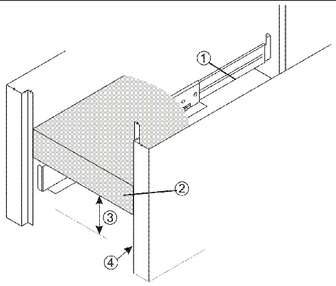
FIGURE 3-2 Attaching the Support Rails to the Cabinet
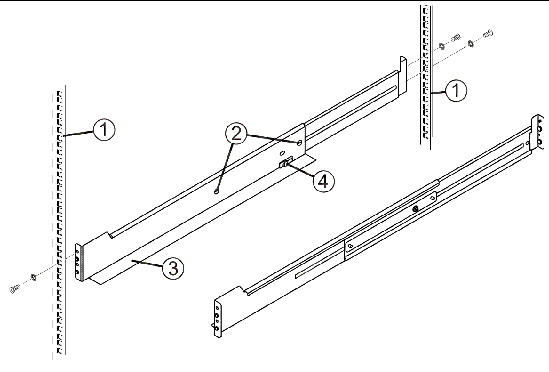
1. If desired, use alignment spacers on the flanges of the mounting rails.
The alignment spacers are designed to fit into the mounting holes in the cabinet and help position and hold the mounting rails. Each support rail comes with two spacers in the front bracket and two spacers in the rear bracket.
2. Be sure the adjustment screws on the support rail are loose so you can extend or contract the support rail as needed.
3. Place the support rail inside the cabinet and extend the support rail until its flanges touch the inside of the cabinet.
4. Insert one large screw through the front of the cabinet and screw into the upper captured nut in the support rail. If needed, add a washer between the screw and the cabinet rail. Tighten the screw.
| Note - Do not insert a screw into the front lower captured nut at this time. This captured nut is used for tray installation. |
5. Insert two large screws through the rear of the cabinet and screw into the upper and lower captured nuts in the rear flange in the support rail. If needed, add a washer between each screw and the cabinet rail. Tighten the screws.
6. Tighten the adjustment screws on the support rail.
7. Repeat Step 1 through Step 6 for the second support rail.
When installing trays, distribute tray weight evenly within the cabinet. One approach is to install the controller tray in the middle portion of the cabinet while allowing room for expansion trays to be placed above and below the controller tray.
1. Install a pair of mounting rails in the cabinet for each controller tray and expansion tray (see Installing Adjustable Support Rails).

|
Caution - Possible hardware damage--To prevent electrostatic discharge damage to the tray, use proper antistatic protection when handling tray components. |

2. Using two people, carefully lift and rest the tray on the bottom left and right rails.

|
Caution - Risk of bodily injury--A fully loaded controller tray weighs approximately 60 lbs (27 kg). Two people are required to safely lift the component. |
3. Carefully slide the tray into the cabinet until the front mounting flanges on the tray touch the vertical face of the cabinet and the rear edges of the tray fit into the clips on the support rails. The tray is correctly aligned when these conditions are met:
4. Secure the front of the tray to the cabinet by inserting a screw through the center hole in each front mounting flange. If you used a washer for the top mounting rail screw, insert a washer between the mounting flange and the cabinet rail. Tighten the screws.
5. Secure the rear side of the tray to each mounting rail by inserting one screw through the side sheet metal of the tray into the captured nut on the mounting rail. Tighten the screw.
6. Replace the end caps that cover the mounting flanges on the front of the tray.
7. Verify that the tray power switches and cabinet circuit breakers are turned off.
8. Connect each tray power supply to a separate power source in the cabinet.
FIGURE 3-3 Drive Channel Ports on the Controller Tray

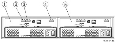
FIGURE 3-4 Expansion Tray Ports--Rear View
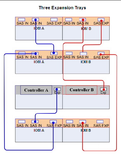
Use the following recommended cabling diagrams for one controller tray and one, two, or three expansion trays.
FIGURE 3-5 Controller Tray Above the Expansion Tray
FIGURE 3-6 Controller Tray Between Two Expansion Trays
FIGURE 3-7 Controller Tray with Three Expansion Trays
1. Use the following table to determine the number of SAS cables that you need:
2. If there is a black, plastic plug in the SAS expansion port on the controller, remove it.
3. Insert one end of the cable into the SAS expansion port on the controller into slot A of the controller tray.
4. Insert the other end of the cable into the port with an up arrow on the IOM into slot A of the expansion tray.
5. Are you adding more expansion trays?
| Note - It does not matter which of the two left-center IOM ports you use to connect to the SAS expansion port on the far-right side. |
FIGURE 3-8 Connecting a Cable from One IOM to a Second IOM
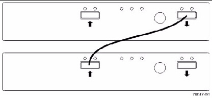
6. In the IOM of the first expansion tray, insert one end of the cable into the port on the far-right side.
7. In the IOM of the next expansion tray, insert the other end of the cable into one of the ports in the left-center of the IOM.
8. Repeat Step 6 and Step 7 for each expansion tray that you add to the storage array.
9. To each end of the cables, attach a label with this information:
For example, if you are connecting controller A to the In port on IOM A in expansion tray 1, the label on the controller end of the cable will have this information:
CtA-Dch1, Dm1-IOM_A (left), In - Controller End
The label on the expansion tray end of the cable will have this information:
Dm1-IOM_A (left), In, CtrlA
10. Repeat Step 2 through Step 9 for the controller in slot B in the controller tray.
© © 2011, Oracle and/or its affiliates. All rights reserved.