| Skip Navigation Links | |
| Exit Print View | |

|
Sun Blade X3-2B (formerly Sun Blade X6270 M3) Service Manual |
Sun Blade X3-2B Model Name Change
Getting the Latest Firmware and Software
About the Chassis Monitoring Module (CMM)
Replaceable Server Module Components
Preparing the Sun Blade X3-2B for Service
Obtaining the Server Module Serial Number
Powering Off the Server Module
Performing ESD and Antistatic Prevention Measures
Remove the Server Module from the Sun Blade Chassis
Remove the Server Module Top Cover
Removing or Inserting Filler Panels
Servicing Sun Blade X3-2B Components
Servicing a Storage Drive (CRU)
Replace the System Battery (CRU)
Servicing USB Flash Drives (CRU)
Servicing a Fabric Expansion Module (CRU)
Servicing a RAID Expansion Module (CRU)
Servicing a Processor and Heat Sink Assembly (FRU)
Servicing the Motherboard Assembly (FRU)
Returning Sun Blade X3-2B to Operation
Install the Server Module Top Cover
Install the Sun Blade X3-2B in the Chassis
Troubleshooting the Sun Blade X3-2B
Diagnosing Server Module Hardware Faults
Troubleshooting Using LED Status Indicators
Using the DIMM and Processor Test Circuit
Troubleshooting Server Module Power States
Firmware and Software Troubleshooting
BIOS Power-On Self-Test (POST) Checkpoints
About POST Code Checkpoint Memory Testing
POST Code Checkpoint Reference
Getting Server Firmware and Software
Firmware and Software Access Options
Available Software Release Packages
See Preparing the Sun Blade X3-2B for Service .
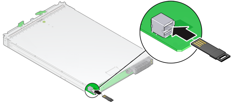
Note - You do not have to remove the server module top cover to access the rear USB ports.
 | Caution - Component damage or data loss. USB flash drives must fit inside the rear of the motherboard. Installing a longer USB drive on the rear port might damage the blade when inserted into the chassis. Drives can be no larger than 7.5 mm wide and 43 .0 mm deep. |
 | Caution - Component damage. Ensure the USB flash drive contacts are in the upward-facing position. |

See Returning Sun Blade X3-2B to Operation .
 | Caution - Component damage or data loss. Flash drives extend past the rear of the blade. Handle the blade with care. |
Use the Oracle ILOM web interface or CLI.
Refer to the Oracle Integrated Lights Out Manager (ILOM) 3.1 Documentation Collection.