JavaScript is required to for searching.
Skip Navigation Links
Exit Print View
Oracle Java CAPS Data Integrator User's Guide     Java CAPS Documentation
search filter icon
search icon

Document Information

Designing Data Integrator Projects

About Data Integrator

Extracting, Transforming, Loading: ETL

Oracle Java CAPS Data Integrator Overview

Extracting, Transforming, and Loading: ETL

Oracle Java CAPS Data Integrator Methodology

Oracle Java CAPS Data Integrator Features

Oracle Java CAPS Data Integrator Architecture

Oracle Java CAPS Data Integrator Design-Time Components

Data Integrator Editor

Oracle Java CAPS Data Integrator Project System

Data Integrator Service Engine

ETL Engine

ETL Service Engine

Data Integrator Monitor

Data Integrator Recovery

Creating Oracle Java CAPS Data Integrator Projects

Connecting to Source and Target Databases

Connecting to a JDBC-Compliant Database

Creating and Connecting to Data Mashup Services

Virtual Database Table Metadata Options

Virtual Database Column Properties

Creating a New Data Integrator Project

To Create a New Project

Creating an ETL Collaboration Using the Wizard

Creating a Basic ETL Collaboration

To Create a Basic ETL Collaboration

Creating an Advanced ETL Collaboration

To Create an Advanced ETL Collaboration

Creating an ETL Collaboration for a Master Index Staging Database

To Create an ETL Collaboration for a Master Index Staging Database

Creating a Bulk Loader ETL Collaboration

To Create a Bulk Loader ETL Collaboration

ETL Collaboration Overview

Execution Strategies

Direct/Simple Execution Strategy

One Pass Execution Strategy

Staging Execution Strategy

Pipeline Execution Strategy

Whitespace Considerations

Explicit and Implicit Joins

Runtime Properties

Data Validation Conditions

About the ETL Collaboration Editor

Configuring ETL Collaborations

Joining Source Tables

To Join Source Tables

To Join Source Tables During Mapping

Modifying an Existing Join

To Join Source Tables

Defining Extraction Conditions and Validations

To Define Extraction Conditions and Validation.

Adding Tables to an Existing Collaboration

To Add Tables to a Collaboration

Forcing Execution Strategies for Collaborations

To Force Execution Strategies for Collaborations

Changing the Database URL for Design Time

To Change the Database URL for Design Time

Configuring Source Table Properties

To Configure Source Table Properties

Configuring Target Table Properties

To Configure Target Table Properties

Using Pre-Created Temporary Staging Tables

Using Temporary Staging Tables

Viewing Table or Join Data

To View Table or Join Data

Viewing the SQL Code

To View SQL Code

Viewing Runtime Output Arguments

To View Runtime Output Arguments

Fine-Tuning the ETL Process

Filtering Source Data Using Runtime Inputs

To Filter Source Data Using Runtime Inputs

Setting the Batch Size for Joined Tables

To Set the Batch Size for Joined Tables

Using Table Aliases with Multiple Source Table Views

Grouping Input Data

To Group Input Data

Viewing and Modifying Table Data

To View and Modify Table Data

Configuring ETL Collaborations

Once you create an ETL collaboration using the Data Integrator Wizard, you can modify the collaboration to customize the processing logic. The ETL Collaboration Editor provides a variety of tools, commands, and operators to configure the ETL process.

Perform any of the following tasks to configure your ETL collaborations:

Joining Source Tables

Data Integrator allows you to join data from multiple sources before extraction. You can create join views by creating a join condition that joins source tables.


Note - For optimal performance, join the most unique columns in the first join and the least unique columns in a second join.


To Join Source Tables

  1. Open the ETL collaboration in the ETL Collaboration Editor.
  2. In the ETL Collaboration Editor toolbar, click Create New Join.

    The Create New Join View dialog box appears.
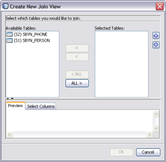

    image:Figure shows the Create New Join View dialog box.
  3. Under Available Tables, select the tables you want to join and then click the right arrow.

    The tables move to the Selected Tables column, and the join is represented graphically in the Preview panel.
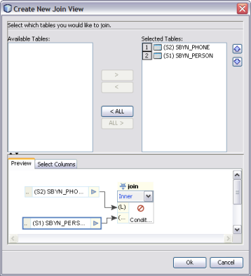

    image:Figure shows a graphic view of a join in the Preview panel.
  4. In the Preview panel, click the down arrow in the join condition and select the type of join to use from the following options.
    • Inner – Use this if all tables to be joined contain the same column.

    • Left Outer – Use this if the results should always include the records from the left table in the join clause.

    • Right Outer – Use this if the results should always include the records from the right table in the join clause.

    • Full Outer – Use this if the results should always include the records from both the right and left tables in the join clause. Full outer joins are only supported for tables from the same relational database. Flat files and the Axion database do not support full outer joins.
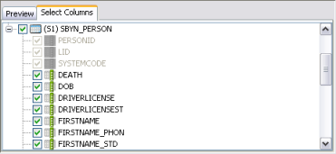
  5. By default, all columns are selected for the join condition. To deselect any columns, click the Select Columns tab and then deselect any columns you do not want to include in the join.
    image:Figure shows the Select Columns panel for a join.
  6. To define the join condition, click inside the join box. On the Edit Join Condition dialog box, do the following:
    1. To view the SQL code while you create the join condition, click the SQL Code tab. To view the join condition graphically, click the Graphical tab.
    2. Define the join condition by dragging column names from the list in the left panel. Join the column names by dragging operators from the toolbar.

      In the example below (shown in both source code and graphical views), PERSONID was dragged from the SBYN_PHONE table first. Then the equals operator, located in the Comparison Operators menu, was dragged next to PERSONID. To complete the condition, PERSONID was dragged from the SBYN_PERSON table.
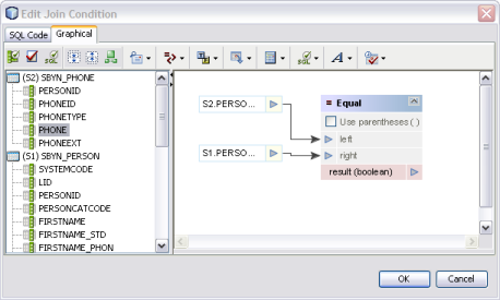
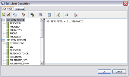
      image:Figure shows a graphical view of a join condition.
      image:Figure shows the SQL script for a join condition.
    3. Define as many conditions as needed.
    4. When you are done defining conditions, click OK.
  7. Click OK on the Edit Join View dialog box.

To Join Source Tables During Mapping

If two source tables are already joined and have columns that are mapped to a target table, you can add another source table to the join by mapping a column in that table to the target table. For example, if source tables S1 and S2 are joined and mapped to target table T1, you can add source table S3 to the join by mapping a column from S3 to T1.

  1. Map a columns from the source target you want to add to the join to the target table that is already mapped to the joined tables.

    A dialog box appears asking whether you want to add the new table to the join.
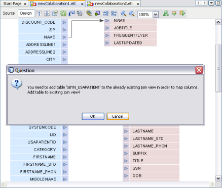

    image:Figure shows the join dialog box.
  2. Click OK to add the new source table to the existing join view.

    The Edit Join View dialog box appears.
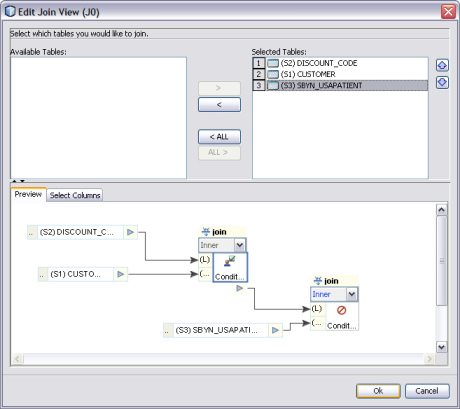

    image:Figure shows a preview of two joins between three tables.
  3. Click in the second join box in the Preview panel.
  4. Define the join conditions by dragging columns and operators onto the canvas.

Modifying an Existing Join

Once you create a join between source tables, you can modify the join condition if needed.


Note - For optimal performance, join the most unique columns in the first join and the least unique columns in a second join.


To Join Source Tables

  1. Open the ETL collaboration in the ETL Collaboration Editor.
  2. In the ETL Collaboration Editor canvas, right-click the join view and select Edit Join View.

    The Create New Join View dialog box appears.


    image:Figure shows the Create New Join View dialog box.
  3. Do any of the following:
    1. Under Available Tables, select additional tables you want to join and then click the right arrow.

      The tables move to the Selected Tables column, and the join is represented graphically in the Preview panel.


      image:Figure shows an example of a join.
    2. In the Preview panel, click the down arrow in the join condition and select the type of join to use from the following options.
      • Inner – Use this if all tables to be joined contain the same column.

      • Left Outer – Use this if the results should always include the records from the left table in the join clause.

      • Right Outer – Use this if the results should always include the records from the right table in the join clause.

      • Full Outer – Use this if the results should always include the records from both the right and left tables in the join clause. Full outer joins are only supported for tables from the same relational database. Flat files and the Axion database do not support full outer joins.

    3. To modify the columns included in the join condition, click the Select Columns tab and then select or deselect any columns.
      image:Figure shows the Select Columns panel for a join.
    4. To define the join conditions, click inside the join box. On the Edit Join Condition dialog box, define the join conditions by dragging column names from the list in the left panel. Join the column names by dragging operators from the toolbar.

      Note - You can perform this step viewing either the source code or a graphical representation of the source code. For information about available operators, see . The figure below shows a simple example of a join condition.

      image:Figure shows the Edit Join Condition window.

Defining Extraction Conditions and Validations

You can set up collaborations to filter data from source tables using extraction conditions and validations. When the collaboration runs, it will only extract data based on the conditions and validations you define.

To Define Extraction Conditions and Validation.

  1. Open the collaboration you want to edit.
  2. Right-click the source table and click Properties.

    The Properties panel appears. By default, the extraction type is configured for conditional extraction. To leave the source data unfiltered, set the Extraction Type property to Full Extraction.

  3. To define extraction conditions, click the ellipsis button next to the Extraction Condition property.

    The Extraction Condition dialog box appears.
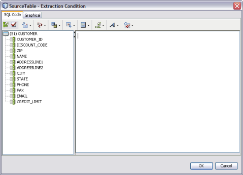

    image:Figure shows the Source Table – Extraction Condition window.
  4. Define the condition by dragging columns and operators onto the canvas, and then click OK.
  5. To define validations for extraction, click the ellipsis next to the Validation Condition property.

    The Validation Condition dialog box appears.
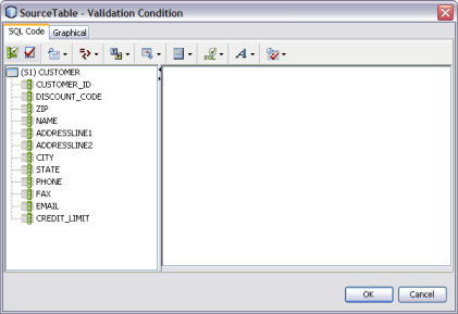

    image:Figure shows the Source Table – Validation Condition window.
  6. Define the condition by dragging columns and operators onto the canvas, and then click OK.
  7. To specify that only unique records be extracted, select the check box next to Select Distinct. To extract all records regardless of duplication, deselect Select Distinct.

Adding Tables to an Existing Collaboration

Once you have defined source and target tables using the Data Integrator Wizard, you can add additional tables as needed. Adding tables is a simple drag and drop procedure.

To Add Tables to a Collaboration

  1. Open the ETL collaboration you want to edit.
  2. On the Services window, expand Databases.
  3. Right-click the database containing the tables you want to add to the collaboration, and then click Connect.
  4. Expand the Tables node under the database you just connected to.
  5. Select a table and drag it onto the ETL Collaboration Editor canvas.
  6. On the dialog box that appears, select either Source Table or Target Table.
  7. If you selected Source Table, do one of the following on the Confirm Join Creation dialog box:
    • To add the new table without creating a join to an existing table, click No.
    • To create a join between the new table and an existing table, click Yes. The Create New Join View dialog box appears. Define the join as described in Joining Source Tables.

Forcing Execution Strategies for Collaborations

The procedure below describes how to force an execution strategy for ETL Collaborations. If you are using Java operators, you must select the Pipeline option. For more information about execution strategies, see Execution Strategies.

To Force Execution Strategies for Collaborations

  1. Open the ETL collaboration you want to edit.
  2. Right-click the ETL Collaboration Editor window and click Properties.

    The Properties panel appears in the right side of the window.
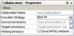

    image:Figure shows the Collaboration – Properties window.
  3. In the Execution Strategy property, select Pipeline or Staging.

Changing the Database URL for Design Time

For database ETL collaborations, the design-time test run uses the same URL, catalog, or schema name to connect to the database table as when the collaboration was created.

You can change the database URL to point to a different location or even a different table name as long as the content structure is the same. Restarting the NetBeans IDE reverts the URL back to its original value.


Note - To change DB2 catalog and schema names, modify the table properties by adding user-defined information in the Expert tab.


To Change the Database URL for Design Time

  1. Open the collaboration you want to edit.
  2. Right-click the ETL Collaboration Editor window and click Database Properties.

    The Edit Database Properties dialog box appears as shown below.
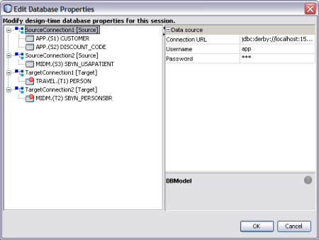

    image:Figure shows the Edit Database Properties window.
  3. In the left panel, select the database whose URL you want to change.
  4. Enter a new URL for the database to connect to during design time.
  5. Enter or verify the user name and password.
  6. Click OK.

Configuring Source Table Properties

You can customize the ETL process by defining certain properties for the source tables. Several properties cannot be changed once they have been set. Changes in the Properties sheet are saved with the ETL collaboration.


Note - To change DB2 catalog and schema names, modify the table properties by adding user-defined information in the Expert tab.


To Configure Source Table Properties

  1. Open the collaboration you want to edit.
  2. Right-click the source table you want to configure, and then click Properties.

    The Source Table – Properties panel appears.
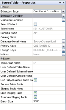

    image:Figure shows the Source Table – Properties window.
  3. Modify any of the editable properties described in the table below.
    Property
    Description
    Extraction Type
    The type of data extraction to perform for the table. Select Conditional Extraction if you will define conditions. Select Full Extraction to extract all data.
    Extraction Condition
    The extraction condition defined for the source table. You can create or edit a extraction condition by clicking the ellipsis button to the right of the property.
    Validation Condition
    The validation condition defined for the source table. You can create or edit a validation condition by clicking the ellipsis button to the right of the property.
    Select Distinct
    An indicator of whether to only select unique records from the source table or to select all records regardless of duplication.
    Table Name
    The name of the source table.
    Schema Name
    The name of the database schema that contains the source table.
    Catalog Name
    The name of the database catalog containing the schema being used.
    Database Model Name
    A name given by Data Integrator to each source table.
    Primary Keys
    Any primary key columns contained in the table.
    Foreign Keys
    Any foreign key columns contained in the table.
    Table Alias Name
    The alias given to the table for identification in SQL statements.
    User Defined Table Name
    A table name to be used during design time.
    User Defined Schema Name
    A schema name to be used during design time.
    User Defined Catalog Name
    A catalog name to be used during design time.
    Use Fully-Qualified Table Name
    An indicator of whether to use the fully qualified name for the table.
    Source Table Prefix
    A prefix to use for the source table.
    Staging Table Name
    The name of the table to use in the internal staging database. Data Integrator also supports dynamic staging table names. The staging table name can be generated in a business process and passed to the collaboration. The staging tables names must be unique.
    Drop Staging Table
    An indicator of whether to drop the internal staging table each time the collaboration is run.
    Truncate Before Load
    An indicator of whether to truncate the internal staging table each time the collaboration is run.
    Batch Size
    The number of records to extract for each batch.

Configuring Target Table Properties

You can customize the ETL process by defining certain properties for the target tables. Several properties cannot be changed once they have been set. Changes in the Properties sheet are saved with the ETL Collaboration.


Note - To change DB2 catalog and schema names, modify the table properties by adding user-defined information in the Expert tab.


To Configure Target Table Properties

  1. Open the collaboration you want to edit.
  2. Right-click the target table you want to configure, and then click Properties.

    The Target Table – Properties panel appears.
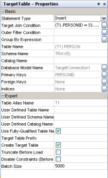

    image:Figure shows the Target Table – Properties window.
  3. Modify any of the editable properties described in the table below.
    Property
    Description
    Statement Type
    The type of SQL statement generated for the table. You can select one of the following options:

    Insert, Insert/Update, Update, or Delete.

    • Insert – Always appends new rows (full load).

    • Insert/Update – Updates an existing row or appends a new row, depending on the evaluation of a condition (upsert).

    • Update – Updates existing rows only.

    • Delete – Deletes existing rows.

    Target Join Condition
    The join condition defined for the target table. You can create or edit a join condition by clicking the ellipsis button to the right of the property.
    Outer Filter Condition
    The filter condition defined for the target table. You can create or edit a filter condition by clicking the ellipsis button to the right of the property.
    Group By Expression
    An expression that groups data by the selected columns. Data Integrator supports extracting aggregated data and applying special transformations before loading to the target table. Group by expressions can only be used with Insert and Update statements. You can create or edit a group by expression by clicking the ellipsis button to the right of the property.
    Table Name
    The name of the target table.
    Schema Name
    The name of the database schema that contains the target tables.
    Catalog Name
    The name of the database catalog containing the schema being used.
    Database Model Name
    A name given by Data Integrator to each target table.
    Primary Keys
    Any primary key columns contained in the table.
    Foreign Keys
    Any foreign key columns contained in the table.
    Table Alias Name
    The alias given to the table for identification in SQL statements.
    User Defined Table Name
    A table name to be used during design time.
    User Defined Schema Name
    A schema name to be used during design time.
    User Defined Catalog Name
    A catalog name to be used during design time.
    Use Fully-Qualified Table Name
    An indicator of whether to use the fully qualified name for the table.
    Target Table Prefix
    A prefix to use for the target table.
    Create Target Table
    An indicator of whether to create the target table. Specify false if the table exists.
    Truncate Before Load
    An indicator of whether to truncate the target table each time the collaboration is run.
    Disable Constraints
    An indicator of whether to disable any constraints on the target table each time the collaboration is run.
    Batch Size
    The number of records to fetch at one time for loading into the target database.

Using Pre-Created Temporary Staging Tables

You can manage temporary tables by configuring source table properties. When all the source tables in an ETL collaboration are configured with a valid table name for the Staging Table Name property, no create or drop privileges are required for the target environment.

Using Temporary Staging Tables

  1. Open the collaboration you want to edit.
  2. Right–click a source table, and select Properties.
  3. Enter a valid table name for the Staging Table Name property.

    Ensure that the source and staging table structures are the same, including column names and data types. If the staging table structure does not match the corresponding source table, the collaboration will fail with an error message.

  4. Select or deselect the Drop Staging Table property to specify whether or not to drop the temporary staging table after the ETL process completes.
  5. Select or deselect the Truncate Staging Table property to specify whether or not to truncate the temporary staging table before each run.

Viewing Table or Join Data

On the ETL Collaboration Editor, you can view data contained in source and target tables. You can also view the output data from a join.

To View Table or Join Data

  1. Open the collaboration you want to view.
  2. To view the data, do one of the following:
    • To view a table's data, right-click on the table and then select Show Data.
    • To view the output data for a join, right-click the join view header and then select Show Data.

    The contents of the selected table or the output data for the join appears in the Data Integrator Output panel.

Viewing the SQL Code

You can view SQL code generated for each table and operator in the ETL collaboration canvas.

To View SQL Code

  1. Open the ETL collaboration you want to view.
  2. Right-click the table or operator on the canvas and click Show SQL.

    The Output section in the lower panel of the NetBeans window displays the generated SQL code, as shown in the following figure.
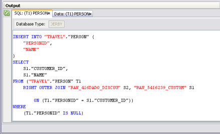

    image:Figure shows the SQL code generated for the select ETL component.

Viewing Runtime Output Arguments

Oracle Java CAPS Data Integrator provides a constant list of output arguments for all ETL collaborations. Runtime outputs can be captured and displayed or written to a file. These messages are made available automatically by the system.

Runtime output arguments include the following:

To View Runtime Output Arguments

  1. Open the collaboration you want to view.
  2. Right-click in the ETL Collaboration Editor, and select Runtime Outputs.

    The Add Output Runtime Arguments dialog box appears.
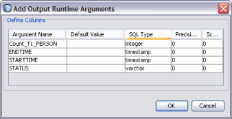

    image:Figure shows the Add Output Runtime Arguments window.