| Skip Navigation Links | |
| Exit Print View | |

|
Oracle Solaris Administration: IP Services Oracle Solaris 11 Information Library |
| Skip Navigation Links | |
| Exit Print View | |

|
Oracle Solaris Administration: IP Services Oracle Solaris 11 Information Library |
1. Planning the Network Deployment
2. Considerations When Using IPv6 Addresses
3. Configuring an IPv4 Network
4. Enabling IPv6 on the Network
5. Administering a TCP/IP Network
7. Troubleshooting Network Problems
11. Administering the ISC DHCP Service
12. Configuring and Administering the DHCP Client
13. DHCP Commands and Files (Reference)
14. IP Security Architecture (Overview)
16. IP Security Architecture (Reference)
17. Internet Key Exchange (Overview)
19. Internet Key Exchange (Reference)
20. IP Filter in Oracle Solaris (Overview)
Part IV Networking Performance
22. Integrated Load Balancer Overview
23. Configuration of Integrated Load Balancer (Tasks)
Installing the Integrated Load Balancer
ILB High-Availability Configuration (Active-Passive Mode Only)
ILB HA Configuration Using the DSR Topology
How to Configure ILB to Achieve High-Availability by Using the DSR Topology
ILB High-Availability Configuration by Using the Half-NAT Topology
How to Configure ILB to Achieve High-Availability by Using the Half-NAT Topology
Setting Up User Authorization for ILB Configuration Subcommands
Administering ILB Server Groups
Administering Back-End Servers in ILB
How to Add a Back-End Server to a Server Group
How to Remove a Back-End Server From a Server Group
How to Re-enable or Disable a Back-End Server
Administering Health Checks in ILB
Displaying Health Check Results
Obtaining Statistical Information Using the show-statistics Subcommand
Displaying the NAT Connection Table
Displaying the Session Persistence Mapping Table
Using Import and Export Subcommands
24. Virtual Router Redundancy Protocol (Overview)
25. VRRP Configuration (Tasks)
26. Implementing Congestion Control
Part V IP Quality of Service (IPQoS)
27. Introducing IPQoS (Overview)
28. Planning for an IPQoS-Enabled Network (Tasks)
29. Creating the IPQoS Configuration File (Tasks)
30. Starting and Maintaining IPQoS (Tasks)
31. Using Flow Accounting and Statistics Gathering (Tasks)
This section describes the implementation of ILB with DSR, half-NAT, and full-NAT topologies.
The following figure shows the implementation of ILB using the DSR topology.

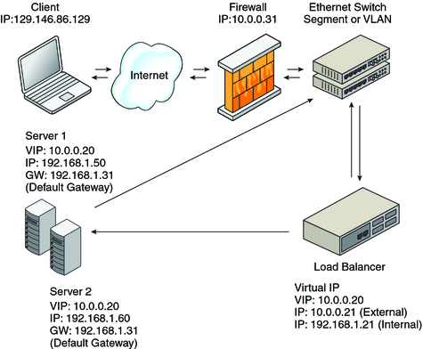
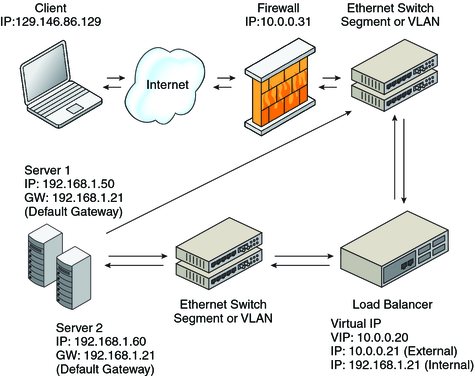
ILB operates in both the half-NAT and full-NAT modes. The general implementation of the NAT topology is as shown in the following figure.

In the half-NAT mode of ILB operation, ILB rewrites only the destination IP address in the header of the packets. If you are using the half-NAT implementation, you cannot connect to a virtual IP (VIP) address of the service from the same subnet on which the server resides.
Table 23-1 Request Flow and Response Flow for the Half-NAT Implementation
|
If you connect the client PC to the same network as that of the servers, the intended server responds directly to the client. The fourth step does not occur and hence the source IP address for the server response to the client is invalid. When the client sends a connection request to the load balancer, the response occurs from the intended server. Henceforth, the client's IP stack correctly drops all the responses.
In that case, the request flow and response flow proceed as shown in the following table.
Table 23-2 Request Flow and Response Flow for the Half-NAT Implementation
|
In the full NAT implementation, the source and destination IP addresses are rewritten to ensure that the traffic goes through the load balancer in both directions. The full NAT topology makes it possible to connect to the VIP from the same subnet that the servers are on. The following table depicts the full-NAT topology for ILB. There is no default route required through the servers. The default route through the load balancer is the router address on subnet C. In this scenario, the load balancer behaves as a proxy.
Table 23-3 Request Flow and Response Flow for the Full-NAT Implementation
|