| StorageTek SL500 Systems Assurance Guide E21060-07 |
|


 Previous |
 Next |
This chapter explains the hardware and features of the SL500 library.
The SL500 library comes with two power options: standard and redundant.
The standard option has one 110–240 VAC, single phase, 50–60 Hz power supply that provides DC power to the library.
The redundant option provides an additional power supply as an optional feature. To provide redundancy, each supply should be plugged into a separate branch circuit.
If something within the power supply or power source fails, the second supply provides power to the entire library until the failed power supply can be replaced or the power source is re-established.
See Table 4-3, Table 4-4, and Table 4-5 for the power specifications. For ordering information, see "Power Cord Numbers and Receptacles" and "Redundant Power Supply".
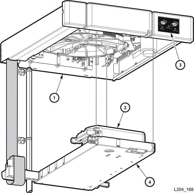
The robotics unit (Figure 4-1) moves cartridges among the storage cells, tape drives, and cartridge access ports (CAPs) and is included with the base module. The three main components of the robotic unit are the:
Z drive assembly—Uses a pulley system to vertically move the X table up and down.
X table assembly—Moves the hand horizontally across the library.
Hand assembly—Contains the wrist motor, gripper assembly, and bar-code scanner:
Z drive assembly
Hand assembly
Keypad (included because of its location)
X table assembly
The electronics for the library consists of two types of cards:
RLC (control) card—Contains the processor and controls the various functions of the library, such as the robotics, sensors, vision system, and the CAP. The RLC card also stores the library configuration and volume serial numbers of the cartridge tapes and their locations.
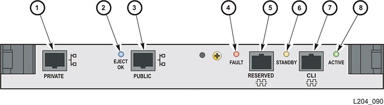
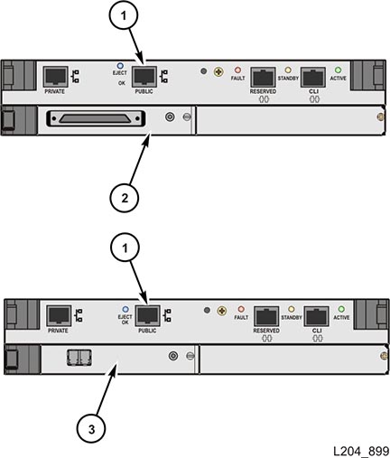
Interface card —Provides the type of interface attachment to the library:
Private Ethernet port is for future use.
Public Ethernet port is for remote service access, SLConsole, and SNMP.
Fault LED indicates that the control card has detected an error.
Reserved for future use.
Not used.
CLI port is an RJ-45 serial port for service representatives.
Active LED indicates the library controller is active.
There are three ways an operator can access the library:
Keypad (standard)
Local operator panel, touch screen (optional feature) - for ordering information, see "Local Operator Panel"
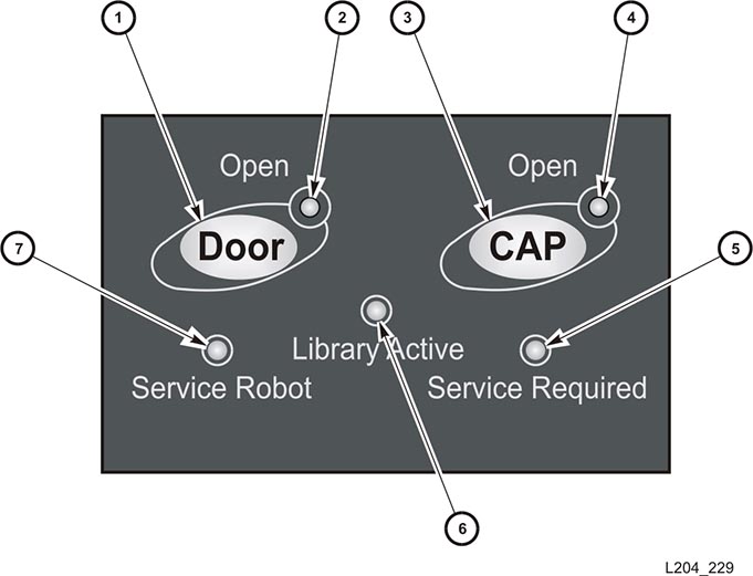
Figure 4-3 shows the keypad, which has two buttons and five LEDs.
The two buttons are:
Door: calls the robot to move to the parked zone.
CAP: opens the cartridge access port.
The five LEDs indicate library activity, service and fault status, CAP and front door status
Open Door button
Open Door indicator
Open CAP button
Open CAP indicator
Service Required indicator
Library Active indicator
Service Robot indicator
The SL500 library uses the StorageTek Library Console (SLConsole), a JavaFoot 1 application that provides a graphical user interface (GUI) for the library. This application is accessed from a remote PC (standard feature) that uses a TCP/IP connection to the library.
The SLConsole can help diagnose problems with the library and its attached devices (tape drives, CAPs, and robot). It allows you to:
Monitor device activity
Load firmware
Print reports
The cartridge access ports (CAPs) are located to the right of the front door of the library.
The base module has one standard CAP:
The library with LTO-only arrays has one 5-slot CAP.
The library with mixed-media arrays has one 4-slot CAP.
Each expansion module has a CAP consisting of two magazines:
The library with LTO-only arrays has two 5-slot magazines.
The library with mixed-media arrays has two 4-slot magazines.
For ordering information, see "Magazines".
The following drives and media are compatible with the SL500 library:
Linear Tape-Open (LTO) Ultrium tape drives:
Hewlett-Packard LTO Generation 2, 3, 4, 5, and 6
IBM LTO Generation 2, 3, 4, and 5
Quantum Super Digital Linear Tape (SDLT) tape drives:
SDLT 320
SDLT 600
DLT-S4
See Appendix A or the tape drive documentation for information about the tape drives that are compatible with the SL500 library. For ordering information, see "Tape Drives" and "Cartridges and Labels".
The SL500 library has a combination of safety features throughout the library, which include:
Key to open and lock the front door
Robotics retracted and in a parked position
Protective modules for the logic cards
Cooling fans to prevent an overheating condition
The robot is retracted into the park zone in the robotics unit when the front door is open. In addition, you must use a key to open the front door.
To open the front door:
Press the Door Open button on the keypad.
The software allows the current job to complete.
The software parks the robot by retracting it into the robotics unit.
When the Door Open indicator light turns on, use the key to open the door.
The front door must be opened with a key to ensure that the data is secure. If the door is not fully closed, a sensor relays the condition to the software for security and safety reasons.
Power is removed from the robot to prevent someone's hand from being injured.
The RLC card, interface card, and the power supply are housed inside protective modules to prevent you from coming into contact with hazardous voltages and sensitive electronics.
For ordering information, see "Power Cord Numbers and Receptacles" and "Redundant Power Supply".
The SL500 library uses the following interface connections:
Ethernet
SCSI LVD
Fibre Channel
Serial Attached SCSI (SAS)
For ordering information, see "Library Interface Changes" and "Interface Cables".
Ethernet connection
SCSI LVD card (MPW/RLW)
Fibre Channel card (MPU2/PUA)
The SL500 library uses standard TCP/IP over Ethernet for the Library Console and Simple Network Management Protocol connections.
Simple network management protocol (SNMP) is an application-layer protocol that performs network management operations over an Ethernet connection.
SNMP allows systems administrators to query the library for configuration, operation, and statistical information plus SNMP allows the library to alert systems administrators of potential problems.
Systems administrators and network managers can use SNMP to monitor and receive status from the library, such as:
Operational state of the library (firmware, serial number, online/offline)
Library elements (columns, panels, slots, CAPs)
Number of storage slots, media types, and tape drives
The SL500 library supports SNMPv3 and Management Information Base (MIB) II or higher.
MIB is a viewable document that contains descriptions about the characteristics for a managed device. These characteristics are the functional elements for that device which can be monitored using SNMP software.
For SNMP information, refer to the SL500 Simple Network Management Protocol Guide.
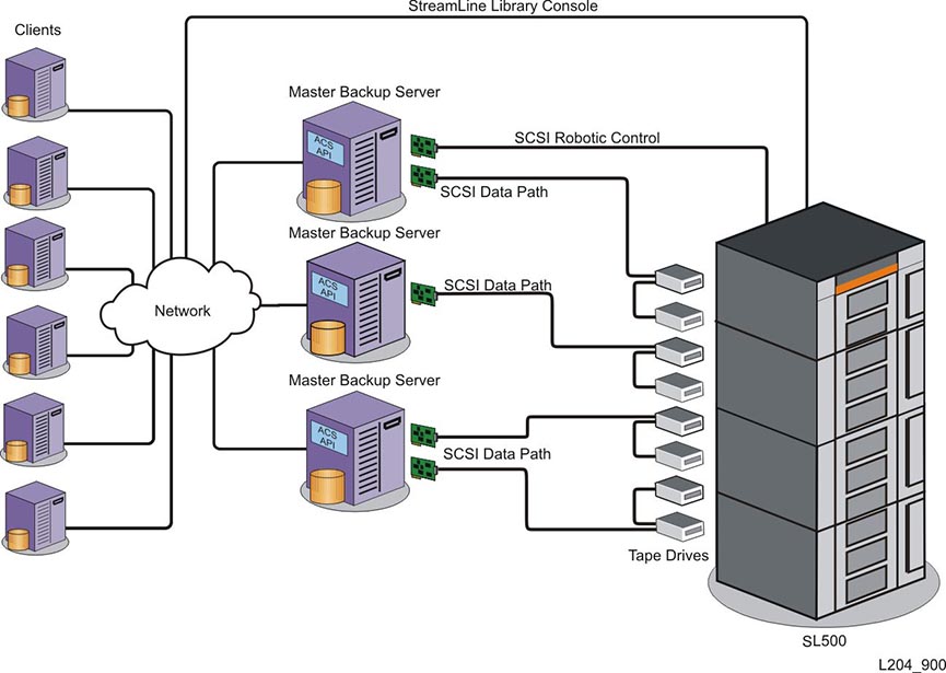
The small computer system interface (SCSI) is an ANSI standard, intelligent peripheral interface that has been in existence since the late 1970's.
The low voltage differential (LVD) implementation is the most recent development of this interface and provides a low noise, low power, low amplitude signal. This lower signal allows for faster switching and higher data transmission speeds. However, this lower signal also reduces the length of cable allowed for an LVD bus. An LVD bus can be up to 12 m (40 ft) long and can support up to 16 devices.
The SL500 library implements the SCSI-3 standard that uses a 16-bit bus, and supports data rates of up to 80 MB/s. SCSI 3 is also know as Ultra3 SCSI, Fast SCSI (Fast-80), or Ultra SCSI (Ultra160).
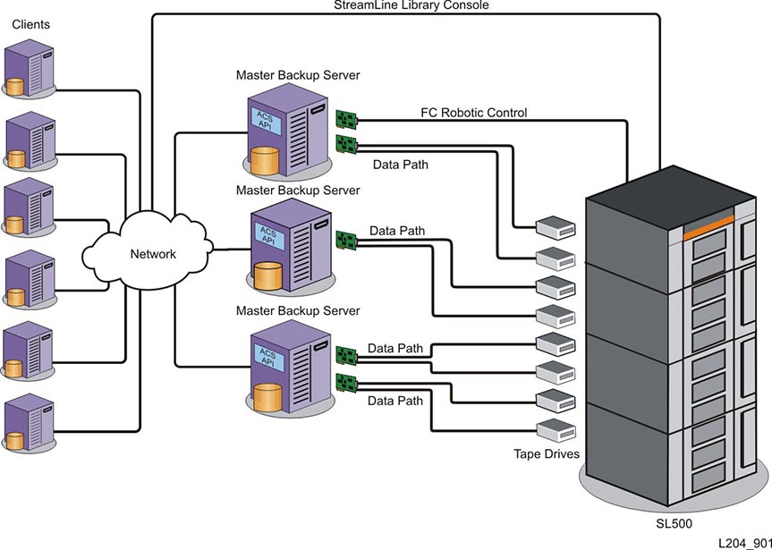
The SL500 Fibre Channel physical interface provides a native connection scheme that supports open system environments. Topologies include:
Switched Fabric: A switched fabric provides dynamic interconnections between nodes and multiple, simultaneous Fibre Channel connections for the network. If the library is connected to a Fibre Channel switch or fabric-capable host, the library configures itself as a switched fabric topology and can support up to 16 million ports logged into the fabric.
Arbitrated Loop: Arbitrated loops provide multiple connections for devices that share a single loop and allow only point-to-point connections between an initiator and target. An arbitrated loop can connect up to 126 ports.
|
Note: While the library supports the arbitrated loop topology, switched fabric is preferred for new or future implementations. |
For cable ordering information, see "Interface Cables".
Serial Attached SCSI (SAS) is a computer bus that moves data to and from devices, for example, tape drives. The SAS interface is a point-to-point serial protocol that uses the standard SCSI command set.
The T10 technical committee of the International Committee for Information Technology Standards (INCITS) develops and maintains the SAS protocol.
Overview
Serial connection.
Multiple Initiator Support.
Gigabit per second data transfer rates.
Scalable for media rates, distance, media, and protocols.
A bridged base unit must be used.
An HP LTO5 tape drive is required as the bridging tape drive.
Components
A typical Serial Attached SCSI system consists of the following basic components:
Initiators: A device that originates requests for processing by a target.
Targets: A device (SL500 library tape drives) containing logical units and target ports that receives requests for processing and sends responses to an initiator.
Expanders: Devices that provide large storage environments the ability to connect multiple targets and initiators through a switched device for scalability and redundancy. SAS benefits include improved performance, simplified cabling with the mini SAS connectors (iPass), and lower power requirements.
For bridged library ordering information, see "Library with Base Module".
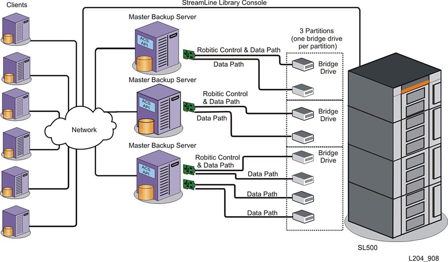
When supported LTO-5 tape drives are installed but dedicated storage-control interface cards are not, command and control information is sent with the data in a single control/data path. When an SL500 library does not detect an Oracle StorageTek MPU2 Fibre Channel or RLW parallel SCSI interface card at startup, the library adopts a bridged configuration by default.
Data and command/control signals travel directly to the Serial Attached SCSI (SAS) or Fibre Channel data interface on the LTO-5 tape drive. The Automation Device Interface (ADI) on a designated LTO-5 bridge drive handles all control communications for the library or library partition. The ADI passes command and control signals to the library controller.
If a bridge drive has not been previously selected, the library selects the first bridge-capable drive that it can find, starting from the top of the library. An unpartitioned bridged library must have one bridge drive. A partitioned bridged library must have a bridge drive for each partition.
Currently, the SL500 library bridging feature is supported on HP LTO-5 Serial Attached SCSI (SAS) and Fibre Channel tape drives.
Library management software components control the library and manage the library database. They also retain volume location and attribute information, plus they perform activities such as mounts and dismounts, enters and ejects.
There are several software components depending on the platform, connection type, and operating system.
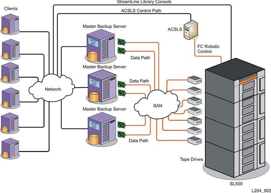
Automated Cartridge System Library Software (ACSLS) is an open systems software package that manages library contents and controls library hardware to mount and dismount cartridges on tape drives. This application provides library management services such as cartridge tracking, pooling, reports, and library control.
For the most current list of independent hardware and software vendors:
Go to http://tapeinterop.us.oracle.com
The Interop Tool is designed for connectivity information on products that are currently sold and supported by Oracle Corporation, regardless of whether such products are now Oracle or Sun branded or third party branded. The configurations listed are reflective of the most up-to-date information reported from various sources, including our testing labs and our technology partners. The Interop Tool lists configurations with valid connectivity, it does not validate the final configuration, the solution or if the configuration will perform in the end user's environment.
The following tables list the specifications for the rack, library and tape drives. See Figure 6-1 and Figure 6-2 for library and rack dimensions.
|
Note: In the following table, HP is a registered trademark of Hewlett-Packard Company. IBM is a registered trademark of International Business Machines. SDLT is a trademark of Quantum Corporation. |
Table 4-1 Library Component Weights
| Component | Weight |
|---|---|
|
Base module with 1 power supply, 2 tape drives, and robotics unit |
44.5 kg (98.0 lb) |
|
Drive expansion module (DEM) with 1 power supply and 4 tape drives |
41.3 kg (91.0 lb) |
|
Cartridge expansion module (CEM) |
20.1 kg (44.2 lb) |
|
Robotics unit |
10.1 kg (22.2 lb) |
|
Power supply |
2.3 kg (5.1 lb) |
|
HP® LTO Ultrium tape drive and tray assy |
3.6 kg (7.9 lb) |
|
IBM® LTO Ultrium tape drive and tray assy |
4.5 kg (9.9 lb) |
|
SDLT™ LVD tape drive and tray assy |
4.2 kg (9.3 lb) |
|
SDLT FC tape drive and tray assy |
4.1 kg (9.0 lb) |
|
DLT-S4 tape drive and tray assembly |
|
|
Tape drive tray assy without tape drive |
|
|
LTO Ultrium cartridge |
221 g (7.8 oz) |
Table 4-2 Environmental Specifications
| Specification | Operating | Storage | Transporting |
|---|---|---|---|
|
Temperature |
10 to 40½C (50 to 104½F) |
10 to 40½C (50 to 104½F) |
-40 to +60½C (-40 to +140½F) |
|
Humidity |
20 to 80% |
10 to 95% |
10 to 95% |
|
Wet bulb (maximum, non-condensing) |
+29.2½C (+84.5½F) |
+35½C (+95½F) |
+35½C (+95½F) |
|
Altitude |
-76 to 3,048 m (-250 to 10,000 ft) |
-- |
-- |
Table 4-3 Library Power without Tape Drives
| Item | Specification |
|---|---|
|
100–240 VAC, single phase |
|
|
50/60 Hz |
|
|
1.4 A @120 V or 0.8 A @240 V |
|
|
180 VA |
The initial warranty period for the SL500 is:
5-by-9 next business day service level
Monday through Friday 8:00 a.m. to 5:00 p.m. Mountain time
12 months from installation
The following regulatory agencies have tested and certified the SL500 library.
Certified by Underwriters Laboratories Inc. (UL) to Standard for Information Technology Equipment -- Safety -- Part 1: General Requirements
UL 60950-1 First Edition
CAN/CSA-C22.2 No. 60950-1-03 First Edition
EN 60950-1 (IEC 60950-1:2001, modified)
CB Scheme in compliance to international Certified Body Scheme requirements with all national deviations
The following statement pertains to products that require a ground connection at the wall outlet.
Norway: Apparatet må tilkoples jordet stikkontakt
Finland: Laite on liitettävä suojamaadoituskoskettimilla varustettuun pistorasiaan
Sweden: Apparaten skall anslutas till jordat uttag
Denmark: For tilslutning af de øvrige ledere, se medfølgende installationsvejledning.
Configuration used for verification and compliance in an SL500 Modular Library with a TCP/IP connection and 2 to 18 tape drives:
Federal Communications Commission (FCC) in compliance to the requirements of FCC 47, Part15, Subpart B and Unintentional Radiators Class A
Voluntary Control Council for Interference (VCCI) (Japan) in compliance to VCCI Class A (Cispr22)
Australia/New Zealand (C-Tick Mark) in compliance to requirements of the Australia/New Zealand EMC Framework AS/NZS 3548: 1995 Class A
European Community (CE Mark) in compliance to the requirements of Electromagnetic Compatibility Directive 89/336 (including all amendments).
Canadian Emissions (ICES) in compliance to the requirements of Canada's Interference Causing Equipment Standard ICES-003 Class A.
Taiwan (BSMI) in compliance to the requirements of Canada's Interference Causing Equipment Standard ICES-003 Class A.
Each fiber-optic interface in this equipment contains a laser transceiver that is a Class 1 Laser Product.
Each laser transceiver has an output of less than 70 µW.
These Class 1 Laser Products follow EN60825-1:1994+A1+A2 and with sections 21 CFR 1040.10 and 1040.11 of the Food and Drug Administration (FDA) regulations.
|
WARNING: Use of controls or adjustment or performance of procedures other than those specified herein might result in hazardous radiation exposure. |
In accordance with safety regulations, a label on each StorageTek Fibre Channel product identifies the laser class of the product and the place and date of the manufacturer. The label appears on top of a Fibre Channel tape drive and near the Fibre Channel connectors on a Fibre Channel tape library.
A copy of the label is shown here:
CLASS 1 LASER PRODUCT
LASER KLASSE 1
APPAREIL A LASER DE CLASSE 1
COMPLIES WITH 21 CFR 1040.10 AND 1040.11
The following laser safety and classification translations are for users in Finland and Sweden:
CLASS 1 LASER
LUOKAN 1 LASERLAITE
KLASSE 1 LASER APPARAT
Footnote Legend
Footnote 1: Java is a general purpose programming language with several features that make the language well suited for use on the internet and with Web browsers.