2 Installation Planning
This chapter provides planning information and requirements to consider before installation of the SL8500 library. Key planning considerations include:
Dimensions and Weights
Ensure there is adequate space for the library, future expansions, and service areas.
Table 2-1 Library Weights and Measures
| Component | Length | Width | Height | Empty WeightFoot 1 | Full WeightFoot 2 |
|---|---|---|---|---|---|
|
DEM |
30.0 in. (76.2 cm) |
67.25 in. (170.8 cm) |
93.15 in. (236.6 cm) |
1,300 lbs (590 kg) |
2,725 lbs (1236 kg) |
|
RIM |
30.0 in. (76.2 cm) |
67.25 in. (170.8 cm) |
93.15 in. (236.6 cm) |
775 lbs (352 kg) |
1,825 lbs (828 kg) |
|
SEM |
37.5 in. (95.25 cm) |
67.25 in. (170.8 cm) |
93.15 in. (236.6 cm) |
850 lbs (386 kg) |
1,775 lbs (805 kg) |
|
CIMFoot 3 |
37.5 in. (95.25 cm) |
67.25 in. (170.8 cm) |
93.15 in. (236.6 cm) |
1,483 lbs (673 kg) |
2,020 lbs (916 kg) |
|
PTP frame |
59.4 in. (150.8 cm) |
6.76 in. (17.17 cm) |
91 in. (231.1 cm) |
N/A |
266 lbs (121 kg) |
|
Front Service Area |
26.0 in. (66 cm) |
71.25 in. (181 cm) |
N/A |
N/A |
N/A |
|
Rear Service Area |
35.0 in. (89 cm) |
74.30 in. (188.7 cm) |
N/A |
N/A |
N/A |
Footnote 1 Base library configuration with N+1 power and four robots; without tape drives or tape cartridges.
Footnote 2 All tape drives, DC power supplies, and cartridges, with 2N power, four robots, doors and facade, but does not include a full rack.
Footnote 3 Weight values are for a CIM with the bulk CAP
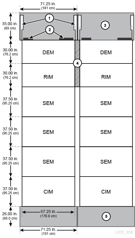
Figure Legend:
-
Rear doors (open)
-
Cable cut outs
-
Rear service area
-
PTP frame
-
Front service area
Tape Drives and Cartridges Weights and Dimensions
The weights below are for reference only, check the drive specific documentation for exact weights and measures.
Table 2-2 Drive Tray Weights and Measures
| Drive Tray | Height | Width | Length | Weight |
|---|---|---|---|---|
|
Drive tray only |
10.8 cm (4.25 in.) |
16.5 cm (6.5 in.) |
85 cm (33.5 in.) |
4.3 kg (9.5 lb) |
Table 2-3 Tape Drive and Cartridge Weights
| Drive Type | Tape Drive Weight (with drive tray) | Cartridge Tape Weight |
|---|---|---|
|
T9840 |
8.2 kg (18.0 lb) |
262 g (9.2 oz) |
|
T9940 |
11 kg (24.3 lb) |
262 g (9.2 oz) |
|
T10000 |
9.4 kg (20.75 lb) |
264 g (9.31 oz) |
|
LTO |
6.9 kg (15 lb) |
210 g (7.4 oz) |
|
SDLT |
6.7 kg (14.8 lb) |
222.5 g (7.85 oz) |
Shipping Weights and Dimensions
The SL8500 library is delivered on pallets that can measure up to 2.5 m (8.25 ft) in length and weigh up to 481 kg (1060 lb). Ensure there are forklifts or pallet jacks that can handle these pallets. If moving between floors, verify the elevator can handle these loads.
Note:
The values listed are estimates and subject to change. The values are for a bulk CAP library.Total Pallet Weights
The total weight of the pallets for various library configurations are listed below. If ordering the optional CAP, increase the total weight by 33 kg (73 lb). CAPs are shipped on their own pallet. Similarly, if ordering redundant robotics, increase the total weight by 65 kg (143 lb). Four additional robots are shipped on an additional #10 pallet. Additional pallets not listed below may be shipped depending on the library features ordered.
Table 2-4 Total Pallet Weights for a Selected Library Configuration
| Configuration | Pallets Shipped | Approximate Total Weight |
|---|---|---|
|
Basic Library |
1, 2, 3, 4, 5, 6, 7, 8, 9, 9A, 10 |
2481 kg (5,470 lb) |
|
One SEM |
1, 2, 3, 4, 4A, 5, 6, 7A, 8, 8A, 9, 9A, 10 |
3090 kg (6,814 lb) |
|
Two SEMs |
1, 2, 3, 4, 4A (x2), 5, 6, 7B, 8, 8A (x2), 9, 9A, 10 |
3709 kg (8,178 lb) |
|
Three SEMs |
1, 2, 3, 4, 4A (x3), 5, 6, 7C, 8, 8A (x3), 9, 9A, 10 |
4336 kg (9,562lb) |
|
Four SEMs |
1, 2, 3, 4, 4A (x4), 5, 6, 7D, 8, 8A (x4), 9, 9A, 10 |
4887 kg (10,777 lb) |
|
Five SEMs |
1, 2, 3, 4, 4a (x5), 5, 6, 7E, 8, 8A (x5), 9, 9A, 10 |
5436 kg (11,987 lb) |
Shipping Pallets Weights and Dimensions
The individual pallet sizes and weights are listed below:
Table 2-5 Shipping Pallets –Weights and Dimensions
| Pallet | Description | Height | Width | Length | Weight |
|---|---|---|---|---|---|
|
1 |
Lower DEM |
205 cm (81 in.) |
97 cm (38 in.) |
185 cm (73 in.) |
480 kg (1058 lb) |
|
2 |
Upper DEM |
87 cm (34 in.) |
97 cm (38 in.) |
185 cm (73 in.) |
160 kg (353 lb) |
|
3 |
Lower RIM |
198 cm (78 in.) |
99 cm (39 in.) |
183 cm (72 cm) |
293 kg (646 lb) |
|
4 |
Upper RIM |
94 cm (37 in.) |
94 cm (37 in.) |
188 cm (74 in.) |
113 kg (249 lb) |
|
4A |
SEM - Frame (one per SEM) |
120 cm (47 in.) |
105 cm (41 in.) |
244 cm (96 in.) |
357 kg (787 lb) |
|
5 |
CIM |
120 cm (47 in.) |
82 cm (32 in.) |
244 cm (96 in.) |
332 kg (732 lb) |
|
6 |
Z-frame |
76 cm (30 in.) |
66 cm (26 in.) |
246 cm (97 in.) |
136 kg (300 lb) |
|
7 |
Basic library rails (no SEMs) |
33 cm (13 in.) |
112 cm (44 in.) |
125 cm (49 in.) |
100 kg (220 lb) |
|
7A |
Rail Kit for one SEM |
33 cm (13 in.) |
112 cm (44 in.) |
218 cm (86 in.) |
182 kg (400 lb) |
|
7B |
Rail Kit for two SEMs |
33 cm (13 in.) |
112 cm (44 in.) |
315 cm(124 in.) |
272 kg (600 lb) |
|
7C |
Rail Kit for three SEMs |
51 cm (20 in.) |
112 cm (44 in.) |
315 cm(124 in.) |
372 kg (820 lb) |
|
7D |
Rail Kit for four SEMs |
51 cm (20 in.) |
112 cm (44 in.) |
315 cm(124 in.) |
395 kg(871 lbs) |
|
7E |
Rail Kit for five SEMs |
46 cm (18 in.) |
107 cm (42 in.) |
310 cm(122 in.) |
416 kg (917 lb) |
|
8 |
Base Module Arrays |
122 cm (48 in.) |
115 cm (45 in.) |
150 cm (59 in.) |
161 kg (355 lb) |
|
8A |
SEM Arrays (one per SEM) |
122 cm (48 in.) |
115 cm (45 in.) |
153 cm (60 in.) |
171 kg (377 lb) |
|
9 |
Covers and Rear Doors |
112 cm (44 in.) |
114 cm (45 in.) |
254 cm(100 in.) |
346 kg (762 lb) |
|
9A |
Bulk CAP, safety door, op panel |
112 cm (44 in.) |
114 cm (45 in.) |
254 cm(100 in.) |
296 kg (652 lb) |
|
10 |
4 Robots (additional pallet with redundant robotics) |
72 cm (28 in.) |
97 cm (38 in.) |
140 cm (55 in.) |
65 kg (143 lb) |
|
PF PLT |
Performance Kit |
61 cm (24 in.) |
107 cm (42 in.) |
107 cm (42 in.) |
38 kg (84 lb) |
Package Component Weights and Dimensions
The package weights and dimensions for additional components are listed below:
Table 2-6 Component Package Weights and Dimensions
| Description | Height | Width | Length | Weight |
|---|---|---|---|---|
|
Rotational CAP |
36 cm (14 in.) |
38 cm (15 in.) |
229 cm (90 in.) |
22 kg (48 lb) |
|
Façade- Upper and Lower (pallet 9) |
13 cm (5 in.) |
49 cm (19 in.) |
242 cm (95 in.) |
19 kg (40 lb) |
|
Copper Kit for Rails 76 in. (pallet 7A) |
8 cm (3 in.) |
44 cm (17 in.) |
196 cm (77 in.) |
9 kg (20 lb) |
|
Copper Kit for Rails 114 in. (pallet 7B ) |
8 cm (3 in.) |
92 cm (36 in.) |
178 cm (70 in.) |
12 kg (25 lb) |
|
Copper Kit for Rails +114in. (pallet 7C) |
8 cm (3 in.) |
92 cm (36 in.) |
178 cm (70 in.) |
14 kg (30 lb) |
|
Drive Bay |
94 cm (36 in.) |
59 cm (23 in.) |
83 cm (32 in.) |
37 kg (80 lb) |
|
HBS |
16 cm (6 in.) |
26 cm (10 in.) |
61 cm (24 in.) |
5 kg (10 lb) |
|
Op Panel/Display |
31 cm (12 in.) |
41 cm (16 in.) |
46 cm (18 in.) |
11 kg (23 lb) |
|
PDU |
28 cm (11 in.) |
74 cm (29 in.) |
74 cm (29 in.) |
9 kg (19 lb) |
|
PDU N+1 |
21 cm (8 in.) |
61 cm (24 in.) |
69 cm (27 in.) |
9 kg (19 lb) |
|
Power Supplies |
23 cm (9 in.) |
26 cm (10 in.) |
46 cm (18 in.) |
5 kg (10 lb) |
|
Drive Tray - Common SL8500 |
31 cm (12 in.) |
33 cm (13 in.) |
102 cm (40 in.) |
14 kg (30 lb) |
|
Drive - Common |
107 cm (42 in.) |
107 cm (42 in.) |
138 cm (54 in.) |
173 kg (380 lb) |
|
LTO Drive on SL8500 Tray |
31 cm (12 in.) |
33 cm (13 in.) |
102 cm (40 in.) |
12 kg (26 lb) |
|
9940 Drive on SL8500 Tray |
31 cm (12 in.) |
33 cm (13 in.) |
125 cm (49 in.) |
18 kg (38 lb) |
|
9940 Drive |
107 cm (42 in.) |
72 cm (28 in.) |
127 cm (50 in.) |
118 kg (260 lb) |
|
Rack Module (19" Rack) |
64 cm (25 in.) |
51 cm (20 in.) |
92 cm (36 in.) |
19 kg (40 lb) |
|
Safety Door |
33 cm (13 in.) |
66 cm (26 in.) |
229 cm (90 in.) |
20 kg (42 lb) |
Installation Site Requirements
Physical Space
Ensure there is adequate space in elevators, passageways, and the construction area. If modules will be added in the future, ensure there is enough space to expand the library (see "Dimensions and Weights").
- Floor
-
Ensure that the weight and coplanar requirements are satisfied (see "Floor Requirements"").
- Transportation
-
If the equipment must be transported on elevators, the elevator cars must be capable of safely handling the weight. Additionally, ensure that the components can pass through doorways and fit in elevators. For more information, see "Shipping Weights and Dimensions" and "Transporting the Library".
- Construction Area
-
The minimum working area (not including the space required for the pallets) is approximately 56 m2 (600 ft2).
- Waste Disposal
-
Sales and service personnel should plan with customers on the disposal of all packing material. Determine if waste bins or recycling containers will be provided on site, or whether an independent company will handle the disposal at additional cost.
Floor Requirements
A raised floor is not required if the site meets all environmental requirements and has adequate airflow (see "Environmental Requirements").
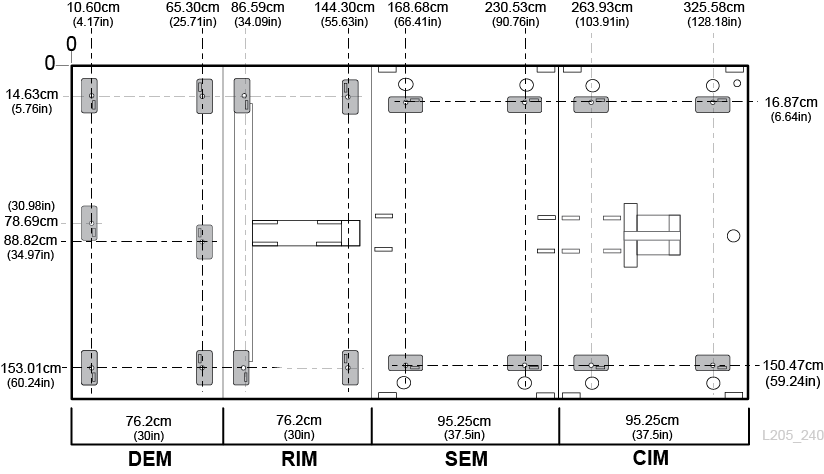
Weight and Load Distribution
Ensure all elevators transporting the library can safely handle the weight (see "Shipping Weights and Dimensions").
Ensure the site floor can support the weight of the library (see Table 2-1, "Library Weights and Measures"). The floor must be capable of supporting 454 kg (1,000 lb) per weight distribution pad, which measure 4 by 8 inches. There are four distribution pads per module, except for the DEM which has six pads.
The 454 kg (1,000 lb) weight represents the modules, plus a factor of safety to accommodate for torque values, installation procedures, component variances, and the floor construction. When adjusting the weight pads during installation, the load distribution may not be evenly spread to each pad—one or more of these pads may be subject to higher loads that near the 454 kg (1,000 lb) value.
Co-planar Requirements
Robots must travel along a level plane throughout the library. Any excessive out-of-plane conditions can cause frame damage, binding, premature wear, or damage to the robots.
The site floor should be laser-leveled before receiving any equipment. The library modules must be level across the width (from left to right) and installed on the same horizontal plane to within ±25 mm (1 in.) tolerance. The floor variations cannot exceed 28 mm ± 0.8 mm (1.1 in. ± 0.0325 in.) throughout the length of the library.
For future library expansion, check the entire floor adjacent to the library for a library complex or in front of the library for SEMs. Adjust each library module so that the rails are on the same plane.
Ceiling Requirements
The DEM and RIM contain an upper module and a lower module. Installing the upper module requires adequate ceiling clearance.
-
Recommended method: Hang the modules on the clamps then swing the upper modules into place. This method requires at least 239 cm (94 in.) of floor-to-ceiling clearance and a minimum of three people to lift the module.
-
Optional method: Remove the clamps (for clearance), lift the upper modules up and slide them over the lower modules. This requires four people to accomplish (one person on each corner) and 236.6 cm (93.15 in) of floor-to-ceiling clearance.
CAUTION:
Check for any equipment that may hang from the ceiling before installing the upper modules.
Height Adjustments
The library height specifications are:
-
Minimum height =231.4 cm (91 in.)
-
Maximum height =236.6 cm (93.15 in.)
Adjust the floor-to-module distance to meet the "Co-planar Requirements". The floor-to-module distance should be adjusted to 25.4 mm ± 0.8 mm (1 in. ± 0.0325 in.). The absolute minimum floor-to-module height permitted is 19 mm (0.75 in.) the maximum height is 47mm (1.85 in.).
Environmental Requirements
For optimal reliability, maintain the environment between the recommended ranges.
| Description | Temperature | Relative Humidity (non-condensing) | Wet Bulb Maximum | Maximum Altitude |
|---|---|---|---|---|
| Operating | 15 to 32°C (60 to 90°F) dry bulb | 20% to 80%Foot 1 | 29.2°C (84.5°F) | 3.05 km (10,000 ft) |
| Storage | 10 to 40°C (50 to 104°F) | 10% to 95% | 35.0°C (95.0°F) | 3.05 km (10,000 ft) |
| Shipping | -40 to 60°C (-40 to 140°F) | 10% to 95% | 35.0°C (95.0°F) | 15.24 km (50,000 ft) |
Footnote 1 Oracle recommends maintaining a relative humidity of 40% to 50%.
Airborne Contaminants
Airborne particulates can damage tape libraries, drives, and tapes. The operating environment for the tape library must meet to the following requirements:
-
ISO 14644-1 Class 8 Environment
-
Total mass of airborne particulates must be less than or equal to 200 micrograms per cubic meter
-
Severity level G1 per ANSI/ISA 71.04-1985
Particles ten microns or smaller are particularly harmful to most data processing hardware. Gasses that are particularly dangerous to electronic components include chlorine compounds, ammonia and its derivatives, oxides of sulfur, and petrol hydrocarbons. In the absence of appropriate hardware exposure limits, health exposure limits must be used.
Humidification with chlorinated water is a common source of airborne chlorine. Appropriately-designed carbon filters must be used to ensure safe levels of airborne chlorine when chlorinated water is used for humidification.
Table 2-8 Gas Limit Recommendations
| Chemical | ASHRAE | OSHA (PEL) | ACGIH | NIOSH |
|---|---|---|---|---|
|
Acetic Acid (CH3COOH) |
Not defined |
10 ppm |
Not defined |
Not defined |
|
Ammonia (NH) |
3500 µg/m3 |
350 ppm |
25 ppm |
Not defined |
|
Chlorine (Cl) |
2100 µg/m3 |
31 ppm (c) |
Not defined |
0.5 ppm (c) |
|
Hydrogen Chloride (HCl) |
Not defined |
5 ppm (c) |
Not defined |
Not defined |
|
Hydrogen Sulfide (H2S) |
50 µg/m3 |
320 ppm (c) |
10 ppm |
10 ppm |
|
Ozone (O3) |
235 µg/m3 |
30.1 ppm |
Not defined |
Not defined |
|
Petrol-hydrocarbons (CnHn) |
Not defined |
500 ppm |
75 ppm |
300 ppm |
|
Sulfur Dioxide (SO2) |
80 µg/m3 |
35 ppm |
2 ppm |
0.5 ppm (c) |
|
Sulfuric Acid (H2SO4) |
Not defined |
1 ppm |
Not defined |
1 ppm (c) |
Some basic precautions to follow:
-
Do not allow food or drink into the data center.
-
Do not store cardboard, wood, or packing materials in the data center clean area.
-
Identify a separate area for unpacking new equipment from crates and boxes.
-
Do not allow construction or drilling in the data center without first isolating sensitive equipment. Dry wall and gypsum are especially damaging to equipment.
Seismic or Earthquake Ratings
The requirements for seismic compatibility vary dramatically throughout the world. It is recommended that you work with local experts familiar with the local code and requirements. Professional Services can also be engaged to help coordinate this activity.
Airflow
In the SL8500 library, air flows front-to-back (CIM-to-DEM). The airflow required depends on the number of components installed in the library. Plan for the cooling requirements of all data center equipment.
Table 2-9 Airflow Requirements (at 1atm, 22°C/72°F)
| Component | Required Airflow | Quantity |
|---|---|---|
|
Tape drive |
0.57m3/min. (20 ft3/min.) each |
64 max |
|
DC power supply |
0.71m3/min. (25ft3/min.) each |
24 max |
|
Rack Modules |
13.59m3/min. (480ft3/min.) each |
4 max |
|
Electronics Module |
4.42m3/min. (156ft3/min.) each |
1 |
A maximum configured library with 64 tape drives, 24 DC power supplies, four rack modules, and the electronic control module would require 112.3 m3/min. (3956 ft3/min.) of air supply to avoid recirculation.
Most configurations are smaller than this and require less airflow. For example, 12 tape drives, 12 DC power supplies, four robots, one rack module, and the electronic control module would require 33.3 m3/min. (1176 ft3/min.).
Power Requirements
A licensed electrician should install the library's external AC wiring. For more information about power requirements of the SL8500, see "Power Configuration Options".
Cabling
The rear library doors have notches on the top and bottom for routing interface and power cables to the tape drives and PDUs. In the table below, left and right are when viewing the rear of the library.
Table 2-10 Door Notch Dimensions
| Location | Length | Width |
|---|---|---|
|
Top Left |
25 cm (10 in.) |
3.8 cm (1.5 in.) |
|
Bottom Left |
40.6 cm (16 in.) |
7 cm (2.75 in.) |
|
Top Right |
25 cm (10 in.) |
3.8 cm (1.5 in.) |
|
Bottom Right |
33 cm (13 in.) |
7 cm (2.75 in.) |
Ethernet, power, and interface cables should be routed through floor or ceiling cutouts of the site. Cutouts should be located near the rear corners of the DEM. The recommended "rough-in" AC feed (power cable) measured from the top of the raised floor to the input of the power distribution unit is 46 cm (18 in.).
Make sure any cabling or conduit inside the library does not interfere with the removal and replacement of any components, such as the DC power supplies, electronics control module, tape drives, or accessory rack equipment. See Figure 2-3 below.
If the existing fire suppression cutouts are not being used, use flexible conduit or cables to route power connections to the AC power supply from above the library. If the fire suppression cutouts are being used, new cutouts should be made in the frame to route conduit or cables to the AC power supply. Optional routing to the left of the tape drive bays may be used for clearance. However, use flexible conduit for the tape drive DC power supply grid.
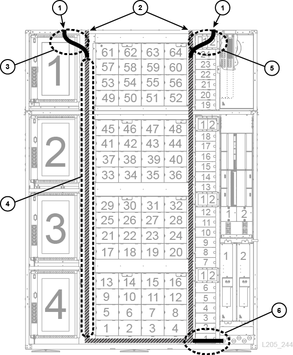
-
Fire suppression cutouts (route cables here if not using fire suppression)
-
New frame cutouts (if fire suppression cutouts are being used)
-
Obstruction to avoid — accessory racks and equipment
-
Optional routing used for clearance, be aware of possible tape drive interference and ethernet cables
-
Obstruction to avoid — HBS and internal switches
-
Obstruction to avoid — tape drive DC power supply
Fire Suppression Planning
The library's smoke detector cuts all power to the library when smoke is detected. You can restore power to the library by resetting the AC circuit breakers on the PDUs.
The library does not ship with a fire suppression system, but there are two 5 cm (2 inch) diameter nozzle openings in each module (see Figure 2-4). Plates, 7 cm (2.75 inch) square and 1.2 mm (0.048 inch) thick, cover the openings and can be drilled to custom fit nozzles. Nozzles must be clear of robotic operations and cannot protrude more than 2.54 cm (1 inch) into the library. Professional Services can assist with fire suppression planning (contact your Oracle sales representative).
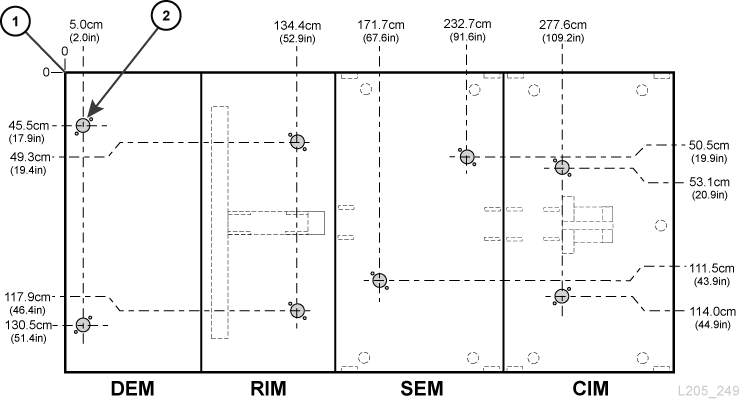
Figure Legend:
-
Datum (measurements are without covers or doors)
-
Nozzle cutout
Pass-thru Port Planning
Although the library complex can expand in either direction, adding a new library to the left is non-disruptive. To expand the library complex in the other direction, you must bring the library offline to re-configuration the system and re-IPL the library. Figure 2-5 shows two examples of a three-library complex.
-
Example 1, on the left, shows the preferred non-disruptive method of adding another library (C) to the left of the library complex.
-
Example 2, on the right, shows the disruptive method. Adding another library (C) to the right of the library complex requires a reconfiguration of LSM numbering.
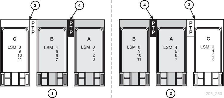
Figure Legend:
-
Preferred, non-disruptive method of installation
-
Disruptive method of installation
-
New library and PTP
-
PTP connecting existing libraries
Time and Personnel
When preparing for an SL8500 installation, it is important to consider personnel requirements, which include safe lifting and time.
- Lifting
-
The upper drive bay and robotic rail modules must be manually lifted for installation. These modules weigh approximately 40 kg (85 lb) and are raised a height of 1.7 m (5.5 ft). There are two methods for installing the upper module. Be aware that one of the methods requires four people to complete. For more information about the upper module installation methods, see "Ceiling Requirements".
- Time
-
The estimated time to physically install a library is about 24 hours. This is based on three qualified people working approximately eight hours each. For initial planning, allow for two days to completely install the library. This provides time to ensure a quality installation and allows for training. Time factors to consider include:
-
Guiding the pallets from the dock to the installation site
-
Removing packaging material when floor space is limited
-
Lifting requirements of 40 kg (85 lb) to attach upper frame assemblies
-
Configuring the library and up to 64 drives with switches and cables
-
Installation Tools
The table below lists the tools contained in the installation kit (part number 24100250). The installation kit is currently not available for order. There are sufficient kits in the field to support installation needs. Oracle service representatives should obtain a kit from their local area and ensure that the following tools are in the kit.
-
Kit dimensions are: 99 cm (39 in.) long, 71 cm (28 in.) wide, and 51 cm (20 in.) high. The kit comes with an extendable handle and wheels.
Table 2-12 Installation Tools for Tool Kit
| Description | Part Number |
|---|---|
|
313921001 |
|
|
Frame jacks with handles (adjustable jack) |
313880803 (check availability) |
|
24100134 |
|
|
24100163 |
|
|
314831204 |
|
|
Torx screwdriver and bits |
Obtain locally |
|
3/8-in. drive ratchet wrench with 6 in. extension 1/4-in., 3/8-in., and 5/16-in. socket for 3/8-in. drive 1/4-in. and 5/16-in. hex(Allen) on 3/8-in. drive |
Obtain locally |
|
3/4-in., 5/8-in., and 9/16 in. combination wrench |
Obtain locally |
|
25 ft tape measure, 2 ft level |
Obtain locally |
|
Utility knife, wire side cutters, rubber mallet |
Obtain locally |
|
Flashlight, step stool, work gloves, safety glasses |
Obtain locally |
|
Volt/Ohmmeter |
Obtain locally |
Track Stop Installation Tools
Both the rack alignment tool kit (418644901) and original track alignment (419894001) tool have been distributed to regional depots. Service representatives can order and check out the special tools as typically done for spare parts. Use two rack alignment kits and two track alignment tools to work both sides of the library in parallel. Installation time for five SEMs is approximately 5 hours.
The rack alignment tool kit (418644901) includes:
-
Short tool (418623102)
-
Long tool (418623002)
-
Serialized shipping container
Additional tools to be acquired locally:
-
1/16 hex Allen driver — required
-
Step stool and knee pads — recommended
-
SL8500 Array Extraction Tool (24100275) — if available
The rack stops (418626901) are packaged in kits of 17 stops and are used in groups of 16 so spares will always be available.
Transporting the Library
There are special considerations to follow when transporting the components of the library to the installation site. If necessary, you can unpack the library components from the pallets to move them to the installation site. Follow the unpacking instructions on the outside packaging material or installation manual. The tables that follow list the specifications for these components.
Adjustable Jacks
You may need a special jack to assist in unpacking, moving, and positioning the larger modules. This jack is part of the tool kit, which is required for an installation (see "Installation Tools").
Module Components
The DEM and RIM come in two parts: a lower and an upper module. The lower DEM is the heaviest component of the library. Use care when moving this component.
The CIM is not pre-assembled and must be constructed on-site. Allow 3 m (10 ft) of space at the end of the box or pallet to unpack these components. A rear section and a front section, called the Z frame must be attached to the floor of the CIM.
The SEM is not pre-assembled and must be constructed on-site. Allow 3 m (10 ft) of space at the end of the box or pallet to unpack these components.
| Module | Pallet | Height | Width | Depth | Weight |
|---|---|---|---|---|---|
| DEM lower | 1 | 173 cm (68 in.) | 168 cm (66 in.) | 76 cm (30 in.) | 386 kg (850 lb) |
| DEM upper | 2 | 58.5 cm (23 in.) | 168 cm (66 in.) | 76 cm (30 in.) | 37 kg (80 lb) |
| RIM lowerFoot 1 | 3 | 176.5 cm (69.5 in.) | 168 cm (66 in.) | 76 cm (30 in.) | -- |
| RIM upperFootref 1 | 4 | 54.6 cm (21.5 in.) | 168 cm (66 in.) | 76 cm (30 in.) | -- |
| SEM floor | 4A | 167.6 cm (66 in.) | 94.6 cm (37.25 in.) | 3.8 cm (1.5 in.) | 67 kg (147 lbs) |
| SEM ceiling | 4A | 167.6 cm (66 in.) | 95.25 cm (37.5 in.) | 3.8 cm (1.5 in.) | 25 kg (54 lbs) |
| SEM center wall | 4A | 227.3 cm (89.5 in.) | 44.5 cm (17.5 in.) | 95.25 cm (37.5 in.) | 80 kg (175 lbs) |
| SEM outer walls | 4A | 231 cm (91 in.) | 186.7 cm (73.5 in.) | 4.4 cm (1.75 in.) | 58 kg (127 lbs) |
| CIM floor | 5 | 167.6 cm (66 in.) | 94.6 cm (37.25 in.) | 3.8 cm (1.5 in.) | 84 kg (185 lbs) |
| CIM ceiling | 5 | 167.6 cm (66 in.) | 95.25 cm (37.5 in.) | 3.8 cm (1.5 in.) | 25 kg (54 lbs) |
| CIM walls | 5 | 231 cm (91 in.) | 186.7 cm (73.5 in.) | 4.4 cm (1.75 in.) | 58 kg (127 lbs) |
| CIM Z-frame | 6 | 227.3 cm (89.5 in.) | 44.5 cm (17.5 in.) | 51 cm (20 in.) | 77 kg (170 lbs) |
| Front doors (bulk CAP) | 9 | 231 cm (91 in.) | 61.5/66 cm (24.25/26 in.) | 8.25 cm (3.25 in.) | 43 kg (95 lbs) |
| Rear doors | 9 | 231 cm (91 in.) | 85.7 cm (33.75 in.) | 10 cm (4 in.) | -- |
| Rack assembly | -- | 48.26 cm (19 in) | 33.65/38 cm (13.25/15 in.) | -- | -- |
Footnote 1 Diagonal stabilizers are attached to help move and handle the RIM.
Rails
Rails are on pallet 7 and are composed of five major parts:
-
Clamps (installed at the factory)
-
Rail extrusions
-
Bottom floor extrusion
-
Geared tracks
-
Power/signal strips
Depending on the number of SEMs, the rails can be the longest components in the library. The extrusion lengths are 1 m (3.3 ft), 2 m (6.4 ft), 3 m (9.5 ft), and 3.9 m (12.6 ft).