1 Library Overview
Library Modules
- Customer Interface Module (CIM)
-
There is one CIM at the front of the library which contains:
-
648 data cartridge slots, 198 slots for diagnostic and cleaning cartridges, and 24 end slots or targeting and drop-off
-
Touch screen operator panel and keypad
-
Two load-sharing DC power supplies
-
Service safety door for maintenance activity
-
CAPs and two elevator assemblies that transfer up to four cartridges each between rails
-
- Storage Expansion Module (SEM)
-
A library can have up to five SEMs. Each SEM contains 1,728 customer-usable data cartridge slots.
- Robotics Interface Module (RIM)
-
In a basic library, the RIM is between the DEM and CIM. In a library with additional storage, the RIM is between the DEM and a SEM. The RIM contains 800 data cartridge slots, pass-thru ports (PTPs) used to connect adjacent libraries in a library complex, and access to the front of the drives.
- Drive and Electronics Module (DEM)
-
There is one DEM at the rear of the library which contains the AC power distribution units (PDUs), load sharing DC power supplies, four accessory racks, electronics control module, and tape drive bay with 64 slots.
Figure Legend:
-
Accessory rack
-
Drive bay
-
DC power supplies
-
Ethernet switches
-
Electronics control module
-
AC PDUs
-
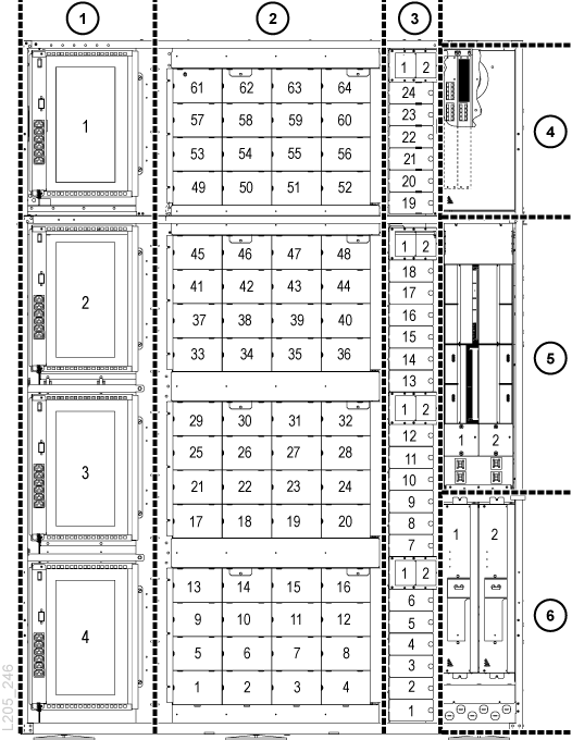
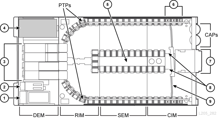
Figure Legend:
-
AC power and electronics control module
-
DC power supplies
-
Tap drive bay
-
Accessory rack
-
Inner wall cartridge slots
-
Reserved slots (E = end stop, X = diagnostic cartridge)
-
Operator panel
-
Elevators
-
Service safety door
Hardware Components
Electronics Control Module
The electronics control module (ECM) is responsible for electronics control, robotic and drive control, and host connectivity. The ECM is located in the rear of the library in the DEM. The main controller cards are the HBCR (library controller) and HBT (drive controller).
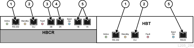
Figure Legend:
-
Serial port (reserved)
-
Serial port (CLI port for service representatives)
-
Primary Ethernet port
-
Dual TCP/IP Ethernet port
-
Ethernet port (reserved)
Command-Line Interface (CLI)
The command-line interface (CLI) is used by Oracle support to configure and diagnose the library. Service representatives can access the CLI through the electronics control module:
-
Serial Port Connection on the HBCR card (RS-232) and a HyperTerminal connection to enter the commands.
-
Ethernet Port Connection (ports 1A, 2A, or 2B) on the HBCR card and a secure shell (PuTTY) to enter the commands.
Redundant Electronics Option
The optional redundant electronics (RE) feature provides failover protection with a second set of controller cards including HBCR, HBT, HBS, and an internal Ethernet switch. If an active controller experiences errors, operations switch automatically to a stand-by controller, with minimal disruption to library and host operations. For more information, see "Redundant Electronics Overview".
Cartridge Access Ports (CAPs)
CAPs import and export cartridges. There are two types of CAPs:
-
Rotational CAPs (legacy)
An SL8500 library cannot contain both CAP types. It may contain either the bulk CAP, or a maximum of two rotational CAPs.
Bulk CAP
The bulk CAP consists of eight CAPs located on the front access doors of the library. There are two CAPs per rail, each with 36 slots (three 12-slot magazines). The library now comes standard with bulk CAPs. To upgrade a library with rotational CAPs to the bulk CAP, see "Cartridge Access Ports".
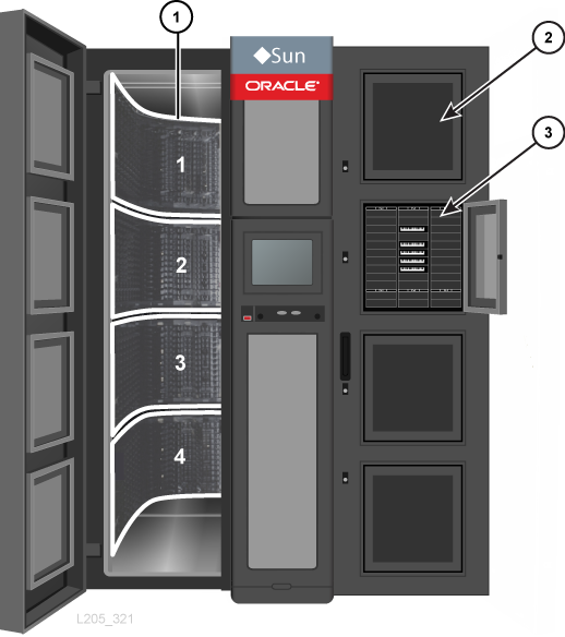
Figure Legend:
-
Rails, numbered 1 to 4 (top to bottom)
-
Closed CAP
-
Open CAP with three 12-slot magazines
Rotational CAPs
A rotational CAP consists of 39 slots (three 13-slot magazines). The library came standard with one rotational CAP, with the option for an additional rotational CAP. Rotational CAPs are located on the right front access door. A single rotational-CAP spans across rails 2, 3, and 4. Entering or ejecting cartridges from rail 1 requires an elevator operation.
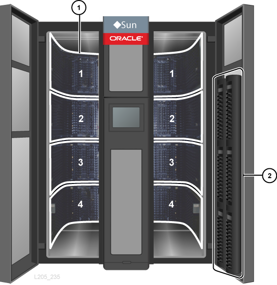
Figure Legend:
-
Rails, numbered 1 to 4 (top to bottom)
-
Rotational CAPs
Robotics
Robots move cartridges between CAPs, elevators, PTPs, storage slots, and tape drives. Each library can have either four (standard) or eight robots (redundant robotics option). The four rails of the library provide power and communication to the robots.
Elevators
An elevator moves cartridges vertically between rails. There are two 4-slot elevators in the front of the library, between the front access doors and the service safety door of the CIM.
Pass-thru Ports (PTPs)
A PTP moves up to two cartridges at a time horizontally between two libraries in a library complex. A separate frame, installed between two adjacent libraries, houses four PTP mechanisms — one PTP for each rail. The PTPs are located on the curved sections of the RIM near the tape drives (see Figure 1-2). Installing or servicing a PTP does not interrupt existing library operations. Each PTP slides out of the frame from the rear of the library for servicing.
Plan ahead before adding a new library to a complex. Although the library complex can expand in either direction, adding a new library to the left (when viewed from the front) is less disruptive (see "Pass-thru Port Planning").
Library Cameras
A camera system (WebCam) allows you to remotely see the inside of the library. There is one camera on each side (left/right) of the library, mounted in the upper frame of the front access door. The library cameras use third party monitoring software and attach to a 10Base-T/100Base-TX Ethernet connection to provide remote audio and video. The table below lists the library camera specifications:
| OS Compatibility | Windows 7, Vista, XP SP3 |
| Minimum Browser Requirements | Windows Explorer 6.0 SP3 |
| Dimensions | Depth: 74mm (2.9 in.); Width: 100mm (3.9 in.); Height: 100mm (3.9 in.)
Weight: 345 g (12.2 oz or 0.76 lb) |
| Connectivity | Ethernet 10Base-T/100Base-TX |
| Camera | ¼ MOS color sensor, 1.3 megapixels
Min illumination: 0.6 lx color, 0.5 lx black/white |
| Video | Max resolution: 1280x960 at 30fps; 8x Digital Zoom
H.264 digital video format; NTSC video format |
| Audio | Built-in microphone, two way audio capable |
Accessory Racks
The SL8500 library provides space for four 19 inch racks. Each rack is 6U (U = 4.4 cm (1.75 in.)) and oriented so the components mount vertically. Oracle cannot mandate what equipment you install, however you should follow the guidelines below to prevent voiding the warranty.
| Description | Value/Range |
|---|---|
|
Maximum weight |
The accessory rack is mounted on slides rated for 80 kg (175 lb). Safe load is 64 kg (140 lb). |
|
Mounting |
Components must function in a vertical position. Rails are not provided; use the mounting hardware supplied by the manufacturer. |
|
Height |
48.25 cm (19 in.) |
|
Width |
27.3 cm (10.75 in.) including power strip |
|
Depth |
72 cm (28 in.) safe length is 66 cm (26 in.) |
|
Mount-points |
72.4 cm (28.5 in.) between mounting points |
|
Thermal Requirements |
880 watts (3,000 Btu/hr) maximum per rack module. |
|
Air flow |
Two cooling fans. Maximum volume per 6u rack module is 241 scfm. |
|
PowerFoot 1 |
200–240 VAC, 50 to 60 Hz, 4 Amps maximum. Six IEC320 C13 outlet receptacles |
|
Regulatory agency compliance |
Minimum requirements: Safety –UL or CSA and Electromagnetic –Class A certification from agencies such as the FCC or BSMI. |
Footnote 1 The N+1 power configuration supports racks 2 and 4. Powering racks 1 and 3 requires the 2N power configuration.
Keypad
There is a keypad on the front of the library with:
-
Two buttons to open and close the CAPs.
-
Eight LEDs that indicate library activity and status.
-
Two safety locks that allow service representatives to place the library in maintenance mode.
-
A red safety button that cuts power to the robots in the library.
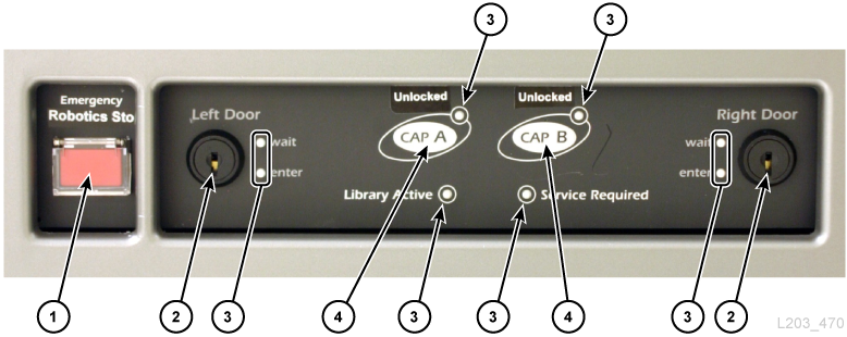
Figure Legend:
-
Emergency robotics stop switch (ERS)
-
Service safety door lock
-
Indicator
-
Lock/unlock CAP button (rotational CAPs only)
Local Operator Panel
The local operator panel is a 12-inch touch screen display on the front of the library. The panel uses StorageTek Library Console (SLC) software to access diagnostics, library status, library and drive monitoring, and functional information.
Service Safety Door
The service safety door is a sliding door that moves to the left or right side of the library, depending upon which maintenance lock is activated. Using the safety door places the library in service mode. The safety door separates the front maintenance area from the library interior so a service representative can safely replace a front frame component while the library remains fully operational.
Note:
Only qualified service representatives with a maintenance key can initiate service mode.Supported Tape Drives
-
StorageTek T-series T9840 A/B/C/D, T9940 B, and T10000 A/B/C/D
-
HP LTO generations 2, 3, 4, 5, and 6
-
IBM LTO generations 2, 3, 4, 5, 6, 7, and 8
-
Quantum SDLT 600 and DLT-S4
Note:
LTO-8 drives can read and write one generation back. LTO-5, 6, and 7 drives can read two generations back and write one generation back. For best capacity and performance, always use cartridges of the same generation as your drives.For more information, see the tape drive section on the Oracle website: http://www.oracle.com/us/products/servers-storage/storage/tape-storage/overview/index.html
OKM Encryption-Compatible Tape Drives
-
StorageTek T10000 A, B, C, D
-
StorageTek T9840 D
-
HP LTO generations 4, 5, 6
-
IBM LTO generations 4, 5, 6, 7
For more information, see "Tape Drive Encryption".
Storage Capacity
The physical capacity of the library depends on the number of SEMs installed. Each SEM increases the slot count by 1,728 (excluding reserved slots). Physical capacity must be activated by a hardware activation file. Only activated slots can be used for data storage and accessed by a client. Inactivated slots are not recognized by the library. You can purchase active capacity in 100, 250, 500, and 1000 slot increments.
To configure capacity, see "Configuring Capacity".
| Library Configuration | Rotational CAP Physical Cartridge Capacity | Bulk CAP Physical Cartridge Capacity |
|---|---|---|
| Base configuration | 1,448 | 1,360 |
| One SEM | 3,176 | 3,088 |
| Two SEMs | 4,904 | 4,816 |
| Three SEMs | 6,632 | 6,544 |
| Four SEMs | 8,360 | 8,272 |
| Five SEMs (maximum) | 10,088 | 10,000 |
Power Configuration Options
The power configuration of the SL8500 library depends on the power source and power redundancy options you select.
Power Redundancy Options
There are two power redundancy options. To determine the number of load sharing power supplies required to support each option, see "DC Power Supplies".
N+1 Power Configuration (standard)
-
Provides DC power redundancy by adding an additional load-sharing power supply to each DC power grid.
-
One load-sharing power supply for every two robots plus one redundant power supply.
-
One load-sharing power supply for every eight drives plus one redundant power supply.
-
Contains two power distribution units (PDUs): one system PDU and one N+1 PDU.
-
Supports two racks (2 and 4).
AC Power Source Options
There are three external AC power options. A licensed electrician should connect the external power cables. For additional information, see "AC Power Connections".
Delta
-
Requires one three-phase input for each system PDU.
-
200–240 VAC, line-to-line, three-phase, 40 Amps, 50–60 Hz (mostly used in the United States).
-
Used when the voltage measured from phase-to-phase is 200-240 VAC.
-
Requires four wires (three phases plus ground). Does not use neutral (a fifth wire).
AC Power Connections
AC wiring from the power source branch circuit must be installed in conduit (flexible or rigid) with a 90-degree elbow-down fitting. If plugs and connectors are required instead of using conduit, the table below lists the Hubbell part numbers (or equivalent) to use.
Table 1-2 Hubbell Connectors and Plugs (IEC 309)
| Description | Part Number |
|---|---|
|
Single Phase US plug 30 amp |
HBL330P6W |
|
Single Phase US connector 30 amp |
HBL330C6W |
|
Single Phase Europe plug 32 amp |
HBL332P6W |
|
Single Phase Europe connector 32 amp |
HBL332C6W |
|
Wye plug 32 amp |
HBL532P6W |
|
Wye connector 32 amp |
HBL532C6W |
|
Delta plug 60 amp |
HBL460P9W |
|
Delta connector 60 amp |
HBL460C9W |
|
NEMA Delta receptacle (250 V, 50 Amp) |
L15-50 R |
|
NEMA Delta plug (250 V, 50 Amp) |
L15-50 P |
DC Power Supplies
The tape drives and robots use the same 1200W DC power supplies. The number of DC load sharing power supplies required depends on the library configuration and power options selected. Use the tables below to determine the number of power supplies to order. For ordering information, see "Power Configurations".
Power Usage
Table 1-6 SL8500 Power Specifications
| Component | Idle Watts | Max Continuous Watts |
|---|---|---|
|
Base Library |
263 |
349 |
|
Redundant Robotics |
92 |
154 |
|
Redundant Electronics |
79 |
98 |
|
Pass-thru Ports (4 mechanisms) |
80 |
92 |
|
Rack space (each) |
68 |
720 |
|
T9840 drive (each) |
79 |
100 |
|
T10000A/B/C drive (each) |
61 |
93 |
|
T10000D drive (each) |
64 |
127 |
|
LTO drive (each) |
30 |
46 |
|
SDLT drive (each) |
38 |
52 |
You can use an online power calculator to estimate the electrical and heat loads for typical operating conditions of a library configuration.:
http://www.oracle.com/us/products/servers-storage/sun-power-calculators/index.html
Optional Library Features
The following features are optional features for the SL8500 library.
Partitioning
Library partitioning is an optional feature that reserves library resources for the exclusive use of specified hosts. Partitioning is enabled with a hardware activation file (see "Activating Optional Features"). You can partition a single library or a library complex using SLC.
-
Can contain up to eight partitions.
-
The smallest slot increment is one array.
-
The smallest drive increment is one drive.
-
Can contain up to 16 partitions.
-
The smallest slot increment is a quarter rail.
-
The smallest drive increment is one drive.
-
Partition boundaries can span across pass-thru ports (PTPs).
-
Requires minimum library firmware 8.31 and SLC 6.25.
-
Requires the following minimum level for library management software:
-
ACSLS 8.3
-
HSC 6.2: PTF L1H16SG (VM)
-
ELS 7.0: PTF L1H15SI (MVS), ELS 7.1: PTF L1H16SJ, ELS 7.2: integrated
-
For more details about the partitioning feature, see "Partitioning the Library".
Media Validation
Media validation allows you to verify all T10000 tape cartridge types using SLC. The following validation methods are available: Basic Verify, Standard Verify, and Complete Verify. Media validation provides a "pass" or "suspect" result for each tape cartridge tested.
Media validation requires a designated pool of T10000C or T10000D tape drives. Up to ten drives can be placed in the media validation pool using SLC. The drives in the pool are not available to hosts. The pool is not considered a partition and does not contain cartridges.
The media validation feature requires minimum firmware SL8500 FRS_8.31, SLC FRS_6.25, and a high memory HBT card. For more information about media validation using SLC, see "Validating Media".
Networking and Communication
The SL8500 library has several connectivity and network topology options. A TCP/IP connection provides the host library interface (HLI) used to communicate with library management applications such as ACSLS or ELS/HSC.
The library controller card is responsible for coordinating all component operations within the library and providing the interface connection with the host. There are two separate Ethernet connections for host to library communications—Ports 2A and 2B.
-
Port 2B provides the primary host connection (standard).
-
Port 2A provides the optional Dual TCP/IP connection or it can be used to connect to SLC.
Host Connectivity Options
There are several host connectivity options that offer flexibility and redundancy to support a variety of customer requirements:.
-
Dual TCP/IP provides two connections between a library or a library complex and an ACSLS or ELS/HSC host(s). Dual TCIP/IP avoids the single point of failure when there is only one connection between the library and the host. See "Dual TCP/IP Overview".
-
Multi TCP/IP provides multiple connections between a library complex and an ACSLS or ELS/HSC host(s). In addition to redundancy in connectivity, this feature also helps reduce contention and improve performance of the library and tape drives. See "Multi TCP/IP Overview".
-
Redundant Electronics (RE) provides redundant library control and communications, and protects against failure should the active HBC/HBCR card fail or if communication to the card is lost. See "Redundant Electronics Overview".
Switched Fabric Topology
In a switched fabric topology, all nodes on the storage area network connect to Fibre Channel switches that provide optimized, dynamic interconnections between nodes. When an SL8500 library is connected to a Fibre Channel switch or fabric-capable host, it automatically configures itself for switched topology. This configuration can support up to 16 million ports on the fabric.
To configure library-attached drives on an SL8500 library, you must use a switched fabric topology. The SL8500 library does not support tape drives configured in arbitrated loops.
Port Bonding
Port bonding combines multiple ports to create redundancy. The SL8500 library uses an active-backup mode. In active-backup mode, there is one bond with two slave ethernet interfaces. If the active interface fails, the backup interface becomes active. With minimum library firmware 8.31 and a second Ethernet switch installed in the library, port bonding is automatically enabled—no command or activation file is required.
Dynamic World Wide Name
The SL8500 library uses the dynamic World Wide Name (dWWN) feature. When enabled, dWWN assigns world wide names to the library drive slots rather than the drives themselves. Therefore, when a drive is replaced, it is assigned the same WWN as the drive it replaced, preventing reconfiguration of the network. Both library and tape drives must have microcode or firmware that supports the dWWN feature.
With the dWWN feature enabled, tape drives do not keep their original WWNs when they are migrated between libraries. A drive that was previously known to the SAN under its own, drive-specific WWN will no longer be recognized. Therefore, you should configure all drive bay slots in the library and verify that the tape drive data path is bound correctly over the SAN.
Library Monitoring
The library can be monitored using SLC or Simple Network Management Protocol (SNMP). Additionally, service representatives can use the Log SnapShot feature to collect logs from the controller cards.
StorageTek Library Console (SLC)
SLC is a GUI application for configuring, monitoring, and managing the SL8500 library. SLC is included with the purchase of an SL8500 library. You can access SLC from the local operator panel, a stand-alone version on a workstation, or through a browser. For installation requirements and additional information, see "Installing StorageTek Library Console".
Library Attach
Library Attach (LibAttach) for Windows Servers is a client application that enables Windows networks to use Oracle's StorageTek storage libraries. LibAttach provides the connection between a Windows application and ACSLS through a TCP/IP network.
LibAttach is included with the SLC download. No additional activation is required. For more information, refer to the Library Attach documentation on OTN.
Simple Network Management Protocol (SNMP)
SNMP is an application layer protocol that performs network management operations over an Ethernet connection. SNMP allows the library to inform the administrator of potential problems. The administrator can query the library for configuration, operation, and statistical informations using SNMP traps. The library supports SNMP v2c and SNMP v3.There is a Management Information Base (MIB) on the controller card which contains information that describes the library, components, and configuration. For more information, see the StorageTek Tape Library SNMP Reference Guide.
Log SnapShot Feature
The Log SnapShot feature is a utility that gathers, compresses, and encrypts logs from a given controller card or from an entire library such as the SL8500 library. A log snapshot can be generated using the CLI or SLC. Only authorized Oracle representatives have access to the data obtained from the Log SnapShot utility.
Service Delivery Platform
The Service Delivery Platform (SDP) is a smart appliance that monitors the library and T-series drives. SDP provides remote diagnosis by logging device events and alerting Oracle support if there is an issue.
For more information, see "Service Delivery Platform".
Library Management Software
Library management software controls the library by allocating drives and requesting library operations, such as entering, mounting, dismounting, and ejecting cartridges. Library management software manages the library database, which tracks volume identifiers (vol-ids), attributes, and locations of cartridges.
There are two main library management options:
Automated Cartridge System Library Software (ACSLS)
ACSLS is centralized, multi-platform library management software for an open-systems environment. ACSLS manages all library operations and shares library resources with any ACSLS-enabled application. A single instance of ACSLS can manage multiple libraries. The key benefits of ACSLS include:
-
Centralized library control across multiple StorageTek libraries, including legacy technology.
-
Optimized library performance through load balancing, automatic request recover and retry, and multiple request processing in parallel.
-
Reduced downtime through dynamic configuration capabilities and queuing commands during short-term library outages.
-
Enriched reporting and management capabilities for ease of use
Enterprise Library Software (ELS)
ELS incorporates multiple software products to monitor and manage tape libraries and virtual solutions for a mainframe environment.
Host Software Component (HSC) and Storage Management Component (SMC)
HSC manages volume pools and communication with the SL8500 library. HSC resides on the host, but is transparent to the operating system. A separate component, SMC, provides the interface between z/OS operating systems and HSC. SMC resides on all MVS hosts that perform tape processing with HSC.
HSC and SMC work together to influence allocations and determine policies, volume locations, and drive ownership. HSC and SMC translate user requests into library commands and provide message handling.
Virtual Tape Control System (VTCS)
VTCS is the host software that enables centralized management of StorageTek virtual tape libraries, such as VSM and VLE. VTCS manages virtual tape volumes and drives, which includes the migration and recall of virtual volumes and the use of real tape cartridges and drives.
Independent Software Vendors (ISVs)
There are a variety of ISVs that support the SL8500 library. Some applications include:
-
ASG Time Navigator
-
CA ArcServe
-
Commvault Simpana
-
Dell NetVault
-
EMC DiskXtender
-
EMC NetWorker
-
FileTek StorHouse
-
HP Data Protector
-
IBM HPSS
-
IBM Tivoli TSM
-
MassTech MassStor
-
DIVA
-
Oracle HSM
-
Oracle Secure Backup
-
Quantum StorNext
-
SGI DMF
-
SGL FlashNet
-
Veritas NetBackup
Not every application is tested on every platform or version. To ensure the software is supported, contact an Oracle marketing or sales representative, or application vendor. Oracle representatives can check compatibility with the Interoperability Tool.
Other Storage System Solutions
The SL8500 library is compatible with several other Oracle products to provide a multifaceted storage solution. This list is not all-inclusive. For more information contact an Oracle sales representative or visit:
http://www.oracle.com/us/products/servers-storage/storage/tape-storage/overview/index.html
Client System Component (CSC)
The CSC allows SMC on MVS to use ACSLS as its library server. One CSC is Library Station, which allows an open systems client to use HSC on MVS as its library server.
Expert Performance Reporter (ExPR)
ExPR software collects performance data and generates reports about status and performance. It provides information on manual tape systems, as well as Nearline and VSM tape systems. ExPR has both an MVS component and a PC component.
Extended High Performance Data Mover (ExHPDM)
ExHPDM is utility software that performs high-speed backup and restore of data sets by interleaving very large block sizes on high-speed, high-capacity tape devices. ExHPDM achieves its speed by treating all data equally regardless of the type. Its only function is to move data from disk to very fast tape and back again.
The ExHPDM software moves blocks of data in parallel from several concurrently executing MVS application programs. The data from the application programs is buffered into 256 KB tape block sizes in the application program's address space, and the 256 KB blocks are interleaved onto single or multiple tape volumes.
Library Content Manager (LCM)
LCM — formerly Expert Library Manager (ExLM) — manages Nearline and VSM resources. LCM optimizes overall performance by assuring there are adequate resources available for a scheduled job. LCM also includes LCM Explorer, a graphical user interface that allows a user to configure LCM by creating configuration files instead of parameter files.
StorageTek Tape Analytics (STA)
STA is an intelligent monitoring application available exclusively for StorageTek Modular Tape Libraries. It simplifies tape storage management and helps make informed decisions about future tape storage investments based on the current health of the tape storage environment.
With STA allows you to monitor multiple libraries from a single, browser-based user interface. STA can manage open systems and mainframe, mixed-media, and mixed-drive environments across multiple library platforms. STA allows you to increase the use and performance of tape investments by performing detailed performance trending analyses. These analyses are based on a regularly-updated database of library operations.
Virtual Storage Manager (VSM)
VSM stores virtual tape volumes on a disk buffer called the Virtual Tape Storage Subsystem (VTSS). VSM then migrates the virtual tape volumes to real tape volumes mounted on real tape drives in the library. The primary host software for VSM is the Virtual Tape Control System (VTCS). VTCS manages virtual tape volumes and drives, which includes the migration and recall of virtual volumes and the use of real tape cartridges and drives.
Ordering
This section provides the part numbers for ordering the SL8500 library and components. Contact Sales Assistance at +1.888.672.2534 for more information.
The tables throughout this chapter provide the part numbers for library components and upgrade options. The ATO number is for initial orders and PTO is for orders after the initial purchase of an SL8500 library.
Ordering Process
-
Physical Configuration — order a base library and optional expansion modules.
-
Hardware Options — select hardware options (CAPs, PTPs, redundant robotics, and redundant electronics).
-
Tape Drives — order tape drives (T10000 and LTO).
-
Tape Cartridges and Labels — order tape cartridges and labels.
-
Power Configurations — select a power redundancy option (N+1 or 2N). Order the required number of power supplies, AC power cords, and PDUs (to calculate requirements, see "Power Configuration Options").
-
Hardware Activation Files — determine the active capacity required. Quantity options include: +100, +250, +500, +1000. Select optional features (partitioning, dual TCP/IP, multi TCP/IP).
-
Cables — select required cables.
-
Support — select maintenance options and professional service options.
Hardware Activation Files
Hardware activation files enable library features. You can download the files through Oracle's Software Delivery Cloud, and then add and remove them from the library using the SLC (see the "Activating Optional Features"). Hardware activation files are required to enable:
-
Active capacity
-
Partitioning
-
Dual TCP/IP
-
Multi TCP/IP
Physical Configuration
Order a base library, select the desired number of SEMs, and corresponding rail kit.
Base Library
The base library includes a CIM, SEM, RIM, DEM, operator panel, four robots, CAPs, service safety door, and web cameras. It is the smallest configuration you can order.
| Base Library Part Number Description | ATO |
|---|---|
| Base Module with 1,360 slots (2,000 active slots) | 7113666 |
| Base Module with 1,360 slots (2,000 active slots) for non-EU countries | 7114548 |
Storage Expansion Modules (SEMs)
The library can contain up to 5 SEMs to increase the capacity of the library.
| SEM Part Number Description | ATO | PTO |
|---|---|---|
| SEM with 1,728 slots (no active slots) | 7100898 | SL8500-EXP-FRZ-N |
Rail Kits
Order one rail kit that correspond to the total number of SEMs.
| Rail Kit Part Number Description | ATO | PTO |
|---|---|---|
| Rail kit for one SEM | 7100886 | XSL8500-1EF-RAIL-N |
| Rail kit for two SEMs | 7100888 | XSL8500-2EF-RAIL-N |
| Rail kit for three SEMs | 7100889 | XSL8500-3EF-RAIL-N |
| Rail kit for four SEMs | 7100891 | XSL8500-4EF-RAIL-N |
| Rail kit for five SEMs | 7100892 | XSL8500-5EF-RAIL-N |
Hardware Options
Accessory Racks
The library provides space for up to four traditional 19-inch racks to be installed in the DEM. Equipment should meet the rack requirements (see "Accessory Racks"). The number of racks supported in the library is determined by the library power configuration:
-
N+1 power configuration = 2 racks max
-
2N power configuration = 4 racks
| Description | ATO | PTO |
|---|---|---|
| 6u Accessory Rack | 7100942 | XSL8500-RACK-Z-N |
Cartridge Access Ports
To upgrade a library with rotational CAPs to the bulk CAP, purchase the upgrade kit listed below.
| Description | PTO |
|---|---|
| Bulk CAP upgrade kitFoot 1 Foot 2 Foot 3 | 7113597 |
| Optional — Additional 12-slot CAP magazine (for Bulk CAPs) | 7113791 |
Footnote 1 The D-link library camera is incompatible with the bulk CAP. If you have a D-link camera, contact your service representative.
Footnote 2 Libraries purchased prior to August 2005 may require an HBN card upgrade. Contact your service representative.
Footnote 3 An HBCR is required for bulk CAP. If you have an HBC card, contact your service representative.
Internal Ethernet Switch
| Description | PTO |
|---|---|
| Internal Ethernet Switch | XSL8500-ETHRNT-Z |
| Internal Ethernet Switch for non-EU countries | 7114566 |
Pass-thru Ports
Connecting two or more SL8500 libraries with pass-thru ports (PTPs) creates a library complex. The PTPs are installed between the DEMs and RIMs of the adjacent libraries.
A single order of PTP mechanisms includes a set of four PTP mechanisms, one mechanism for each rail area between the libraries. The ILC kit includes the Ethernet hub and cables to connect the additional libraries. Each ILC kit can support up to five libraries in a complex. Order two kits for a complex with more than five libraries.
| Description | ATO | PTO |
|---|---|---|
| PTP without mechanisms (frame only) | 7100926 | XSL8500P-BLANK-N |
| PTP mechanisms (set of four) | 7100919 | XSL8500-MECH-Z-N |
| PTP mechanisms (set of four) for non-EU countries | 7114553 | 7114568 |
| Hub and intra-library communications (ILC) kit | 7100924 | XSL8500P-HUB-Z-N |
| Hub and intra-library communications (ILC) kit for non-EU countries | 7114552 | 7114567 |
Redundant Electronics
The optional redundant electronics (RE) feature provides failover protection with a second set of controller cards including an HBCR, HBT, HBS, and an internal Ethernet switch. For upgrades, order both PTO parts listed below.
| Description | ATO | PTO |
|---|---|---|
| Redundant Electronics | 7100917 | XSL3000-REDELCT-Z and 7101366 |
| Redundant Electronics for non-EU countries | 7114551 | 7114540 and 7114565 |
Robots
Each library comes standard with four robots. Optionally you can order four additional robots for redundant robotics. See also "Power Configurations".
| Description | ATO | PTO |
|---|---|---|
| Redundant robots (four additional) | 7100928 | XSL8500-4BOT-Z-N |
| Redundant robots (four additional) for non-EU countries | 7114550 | 7114564 |
Service Safety Door
| Description | PTO |
|---|---|
| Service Safety Door | XSL8500-SVDR-Z-N |
Touchscreen Op Panel
| Description | PTO |
|---|---|
| Touch Screen Op Panel | XSL8500-TSOP-Z-N |
Tape Drives
See the tape storage area on the corporate website for additional information: http://www.oracle.com/us/products/servers-storage/storage/tape-storage/overview/index.html
For more information about encryption, see the Oracle Key Management Overview and Planning Guide on OTN.
Tape Drive Encryption
There are two encryption key management options:
-
Application-managed — an application manages the keys using the data path.
-
OKM-managed — Oracle Key Manager (OKM) appliance manages the keys using an ethernet connection outside the data path which is generally more secure.
Support for application-managed and OKM-managed encryption depends on the drive type.
T10000 Encryption
All T10000 generations are encryption-ready, however enabling either application-managed or OKM-managed encryption requires a T10K-EKEY-A-N encryption activation permit. You can order an encryption activation permit at any time (during initial purchase or afterwards). After purchasing the permit, use Virtual Operator Panel (VOP) to enable encryption. T10000C and T10000D drives no longer require encryption license keys to enable encryption.
LTO Encryption
OKM-managed encryption requires an LTO-ENCRYPT-ACTIVE encryption activation permit. Application-managed encryption using the data path does not require a permit.
HP LTO 5 and 6 drives support both OKM-managed and application-managed encryption.
IBM LTO 5, 6, and 7 drives require an encryption card in the drive tray to interface with OKM (LTO 5 and 6 use the Belisarius card. LTO 7 may have either the Belisarius card or the LKM card. LTO 7 drive trays with LKM began shipping in July 2018). Note to use drive trays with LKM cards, the library must be in ADI mode.
You may purchase a drive with or without OKM compatibility. To upgrade a non-OKM-compatible IBM drive, you can purchase a kit to add the encryption card.
Re-using Encryption Activation Permits
If you previously purchased an activation permit for an older drive, you can re-use the activation permit when upgrading to a newer generation drive of the same family, as long as the total number of encryption enabled drives does not exceed your total number activation permits for that family. For example, if you have six T10K-EKEY-A-N activation permits, you can only have a total of six encryption-enabled T10000 drives (regardless of generation).
T10000 Drives
There may be other configurations for the T10000 tape drives than those listed below. For more information, see the drive specific Systems Assurance Guide on the OTN.
| T-series Tape Drive Type | Part Number |
|---|---|
| T10000D 16Gb Fibre Channel | 7105797 |
| T10000D 16Gb FICON | 7105798 |
| T10000 encryption activation permit for one driveFoot 1 | T10K-EKEY-A-N |
Footnote 1 See "T10000 Encryption" and "Re-using Encryption Activation Permits" above.
LTO Drives
| LTO Tape Drive Type | Part Number |
|---|---|
| IBM LTO8 Fibre Channel no OKM compatibility | 7118442 |
| IBM LTO7 Fibre Channel with OKM compatibility | 7113987 |
| IBM LTO7 Fibre Channel no OKM compatibility | 7113988 |
| Encryption Upgrade Kit for IBM drives (Belisarius card) | 7113290 |
| LTO encryption activation permit for one driveFoot 1 | LTO-ENCRYPT-ACTIVE |
Footnote 1 See "LTO Encryption" and "Re-using Encryption Activation Permits" above
Tape Cartridges and Labels
To order tape cartridges or labels:
-
Call 1.877.STK.TAPE
See the tape storage area on the corporate website for additional information: http://www.oracle.com/us/products/servers-storage/storage/tape-storage/overview/index.html
Power Configurations
You must selected a power redundancy and AC power configuration. Refer to "Power Configuration Options" for more information.
| Power Options | ATO | PTO |
|---|---|---|
| Delta Power | 7100930 | XSL8500-DELTAZ-N |
| Delta Power for non-EU countries | 7114555 | 7114571 |
| Wye Power | 7100938 | XSL8500-WYE-Z-N |
| Wye Power for non-EU countries | 7114556 | 7114572 |
| Single Phase Power | 7100929 | XSL8500-1PH-Z-N |
| Single Phase Power for non-EU countries | 7114554 | 7114570 |
DC Power Supplies
The number of DC 1200W power supplies required depends on the power configuration (N+1 or 2N) and the number of components in the library. Refer to"DC Power Supplies" to determine the number of power supplies required.
| DC Power Supply Description | ATO | PTO |
|---|---|---|
| DC 1200W Power SupplyFoot 1 | 7100931 | XSL8500-DR-PWR-Z-N |
Footnote 1 Power supply for tape drives and robotics
Hardware Activation Files
The following features are enabled with a hardware activation file. For information about downloading and installing activation files, see "Activating Optional Features".
| Library Feature Description | ATO | PTO |
|---|---|---|
| Dual TCP/IP host interface activation permit | 7100932 | XSL8500-DTCPIP-N |
| Multi-TCP/IP host interface activation permit | XSL8500-MTCPIP-N |
Capacity Activation
For libraries with library firmware FRS_7.x and higher, use the table below for slot upgrade part numbers.
| Active Capacity Description | ATO | PTO |
|---|---|---|
| 100 Slot Upgrade activation permit | 7100880 | 7100945 |
| 250 Slot Upgrade activation permit | 7100881 | 7100946 |
| 500 Slot Upgrade activation permit | 7100882 | 7100947 |
| 1,000 Slot Upgrade activation permit | 7100883 | 7900948 |
Cables
The following sections provide information about the different interface cables. When ordering cables, keep this in mind:
-
Riser cables can be used in computer rooms and are not classified according to flammability or toxic gas emissions.
-
Plenum cables are designed for installation in air ducts and manufactured to meet UL standards for flammability and produce little smoke.
Ethernet Cables
The library uses Ethernet cables for TCP/IP connections, which include host and library-to-library communications.
| Ethernet Cable Part Number Description | PTO |
|---|---|
| CAT5E, 8 ft, 24 AWG, Shielded | CABLE10187033-Z-N |
| CAT5E, 35 ft, 24 AWG, Shielded | CABLE10187034-Z-N |
| CAT5E, 50 IN, 24 AWG, Shielded | CABLE10187035-Z-N |
Fiber-Optic Cables
LC connectors are the industry standard for all 2 Gbps or higher Fibre Channel devices. SC connectors are the standard for 1 Gbps Fibre Channel devices such as the T9840A tape drive. The SL8500 drive tray requires LC plugs for connection on the rear panel. When re-using T9840A tape drives, you will need to use an SC to LC adapter. The SL8500 drive tray only supports LC connectors.
| LC-LC 50/125 Micron Fiber-Optic Cables | ATO | PTO |
|---|---|---|
| 50 m (164 ft) FC cable OM4, 50/125 Duplex riser | 7106951 | 7106952 |
| 50 m (164 ft) FC cable OM4, 50/125 Duplex plenum | 7106953 | 7106954 |
| 3 m (9.8 ft) Duplex riser | CABLE10800340-Z-A | CABLE10800340-Z-N |
| 5 m (16.4 ft) Duplex riser | CABLE10800341-Z-A | CABLE10800341-Z-N |
| 10 m (32.8 ft) Duplex riser | CABLE10800310-Z-A | CABLE10800310-Z-N |
| 10 m (32.8 ft) Duplex plenum | CABLE10800313-Z-A | CABLE10800313-Z-N |
| LC to LC, 9/125 Micron Two Gigabit Fiber-Optic Cables | Part Number |
|---|---|
| 10 m (32.8 ft) Duplex, Riser | CABLE10800331-Z-N |
| 50 m (164 ft) Duplex, Riser | CABLE10800333-Z-N |
| 100 m (328 ft) Duplex, Riser | CABLE10800306-Z-N |
| 10 m (32.8 ft) Duplex, Plenum | CABLE10800330-Z-N |
| 50 m (164 ft) Duplex, Plenum | CABLE10800332-Z-N |
| 100 m (328 ft) Duplex, Plenum | CABLE10800305-Z-N |
Support
Service and support representatives are available to assist with hardware and software problem resolution. During the initial order and installation planning, you can contact local and remote support with any questions.
Service Delivery Platform
The Service Delivery Platform (SDP) is a support enhancement solution that provides faster problem resolution, analysis, trending, and improved diagnostic capabilities. The SDP consists of a smart appliance placed at the customer site that connects to the library and any StorageTek T-series tape drives. The SDP collects device events and alerts support analysts, providing remote diagnosis and auto service requests (ASR).
For more information, customers should contact an Oracle representative, or visit: http://www.oracle.com/technetwork/systems/asr/documentation/oracle-installed-storage-330027.html
Oracle Premier Support for Systems
Oracle Premier Support is a fully integrated support solution which features:
-
Complete system coverage and unlimited 24/7 access to Oracle system specialists
-
Essential product updates, such as firmware
-
Personalized, proactive IT support and rapid-response hardware service
For more information, visit: http://www.oracle.com/us/support/index.html
Contacting Support
The Oracle Global Customer Support Contacts Directory can be found at: http://www.oracle.com/us/support/contact-068555.html
To submit, update, or review service requests, go to My Oracle Support at: https://support.oracle.com/