7 Administering JD Edwards EnterpriseOne on an IBM i Cluster
This chapter contains the following topics:
-
Section 7.9, "Setting Up Object Configuration Manager for Clustering"
-
Section 7.10, "Distributing the ODBC Setup from the Deployment Server"
-
Section 7.11, "Identifying the Cluster Name on the Deployment Server"
7.1 Understanding IBM i Clustering
IBM i clustering is a platform-specific software solution that provides users with continuous access to Oracle's JD Edwards EnterpriseOne even when the primary server becomes unavailable. You can switchover from a primary server to a backup server either automatically or manually.
An IBM i cluster consists of more than one node, although not necessarily more than one physical machine. For example, you can use logical partitioning to represent several nodes on a single machine, or you can maintain more than one IBM i machine, each of which represents a cluster node.
A cluster name is associated with a floating or takeover IP address. Each node in the cluster has an IP address associated with a TCP/IP interface. At any time, only one node in the cluster has the interface activated. That node is the primary node, on which JD Edwards EnterpriseOne services are running. All other nodes in the cluster are designated as backup nodes, and the TCP/IP interface is inactive.
IBM i nodes participating in a single cluster use the cluster software to do these tasks:
-
Replicate object and data changes from the primary node to backup nodes so that any backup node can assume the primary server role when an interruption in service occurs.
-
Read a specifier file that identifies the objects and data that must be replicated and the locations of those specified objects and data.
-
Use a backup node to monitor the primary node for availability.
-
If the primary node becomes unavailable, use an exit program to activate the floating IF address on the first backup node associated with the cluster name.
-
Restart JD Edwards EnterpriseOne on the first backup node, thus making it the primary node.
-
Queue changes to objects and data so that an original primary node can be updated once it becomes available for service.
You can use JD Edwards EnterpriseOne and IBM i clustering software to support two-tier configurations (IBM i functioning as data server only), virtual three-tier configurations (IBM i functioning as both logic server and data server), and three-tier server configurations (separate IBM i machines functioning as a logic server and a data server).
IBM recognizes three partners who market the IBM i clustering solution:
-
DataMirror Corporation
-
Lakeview Technologies
-
Vision Solutions
For more details on these vendor solutions, consult the CNC specialist.
7.1.1 IBM i - JD Edwards EnterpriseOne Architecture with Clustering
This graphic illustrates the main components of a virtual three-tier clustering setup:
Figure 7-1 IBM i Clustering Architecture — normal operation
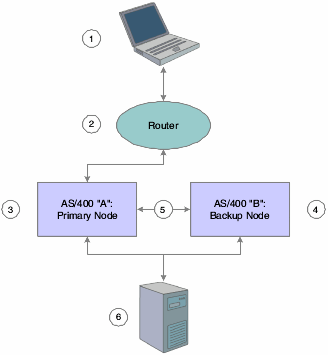
Description of "Figure 7-1 IBM i Clustering Architecture — normal operation"
The roles of each component in the cluster are as follows:
-
Workstation (1) attempts to access the primary node.
-
Router (2) directs workstation access request to the primary node using the cluster name and the associated floating IP address.
-
Primary node (3) provides services to the workstation and sends changes to objects specified in the specifier file to the backup node.
-
Backup node (4) monitors primary node and applies changes to data and replicated objects using static IP address (5).
-
Deployment server (6) updates both primary and backup nodes with changes to application objects using package deployment.
This graphic illustrates the role of each component in the clustering environment when a failover scenario occurs:
Figure 7-2 IBM i Clustering Architecture — failover scenario
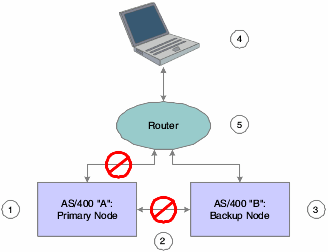
Description of "Figure 7-2 IBM i Clustering Architecture — failover scenario"
The roles of each component in the cluster in the failover scenario are as follows:
-
Ex-primary node (1) ends communication with the workstation and the backup node.
-
Object and data changes using static IP address end, as does monitoring of nodes(2).
-
Clustering software on IBM i B detects failure of IBM i A, activates failover TCP /IP interface, applies queued changes to objects listed in clustering specifier file, and makes JD Edwards EnterpriseOne services available on IBM i B (3).
-
Workstation (4) requests server services and waits for a response for a length of time specified in its jde.ini file. After JD Edwards EnterpriseOne notifies the workstation of a lost server connection, the workstation attempts to reconnect.
-
Router (5) receives reconnection attempt from workstation and directs request to the new primary node using the cluster name and the associated floating IP address.
After the failover, the ex-primary node should eventually become available once again for service. This graphic illustrates the role of each component in the clustering environment when the return to normal operations occurs:
Figure 7-3 IBM i Clustering Architecture — return to normal
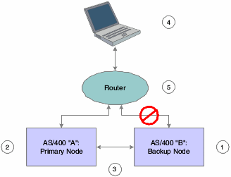
Description of "Figure 7-3 IBM i Clustering Architecture — return to normal"
The roles of each component in the cluster in the return to normal operations are as follows:
-
The clustering software stops the failover interface on IBM i B (1), ending communication with the workstation.
-
The clustering software starts the failover interface on IBM i A (2) and applies any queued changes to objects listed in the clustering specifier file.
-
Replication and monitoring services restart (3).
-
Workstation (4) requests server services, waits for a response for a length of time specified in its jde.ini file. After JD Edwards EnterpriseOne notifies the workstation of a lost server connection, the workstation attempts to reconnect.
-
Router (5) receives the reconnection attempt from workstation and directs the request to the primary node using the cluster name and the associated floating IP address.
For a full discussion of platform, hardware, and LAN and WAN configurations, consult IBM clustering documentation as well as documentation provided by each of IBM's approved clustering software partners.
7.1.2 JD Edwards EnterpriseOne Objects Used with IBM i Clustering
The JD Edwards company requires you to download the latest IBM i Clustering objects from the Update Center. This topic discusses each of the JD Edwards EnterpriseOne objects required for use with IBM i clustering software:
-
Specifier file
-
SETOWCLST command
-
Application data areas
-
Exit program
Consult the CNC specialist if you need to modify any of these files.
Specifier File
The specifier file identifies all JD Edwards EnterpriseOne objects and data that must be replicated from the primary server node to the backup node. Replication ensures that you have a backup of essential business information on the backup node should the primary node fail.
The information in the specifier file enables the creation of application and data cluster resource groups (CRGs). Application CRGs identify nodes in a cluster that can be used to run a particular program or group of programs on the enterprise server. Data CRGs represent the locations of data and objects in the cluster. With this information established, the clustering software is able to replicate the specific set of objects and data to a specific server node.
Note:
Do not attempt to modify the specifier file directly. To customize the file, consult the CNC specialist.This table summarizes the items that must be replicated for JD Edwards EnterpriseOne-IBM i clustering:
| Replication Item | Files and Directories for Replication |
|---|---|
| All data used for an environment | Examples:
PRODDTA/*PF PRODCTL/*PF |
| Object Librarian | OL900/*PF |
| Central Objects | COPD900/*PF |
| Data dictionary | DD900/*PF |
| PrintQueue Directory | /E900SYS/printqueue |
| JD Edwards EnterpriseOne jobs table (F986110) | SVM900/F986110 |
Note:
Clustering vendor solutions shouldn't replicate JD Edwards EnterpriseOne specification files in the integrated file system (IFS).SETOWClST Command
You can use the SETOWCIST command to access the specifier file. This command is necessary to update the specifier file if you add, remove, or modify the name or location of a JD Edwards EnterpriseOne IBM i library or object.
Application Data Areas
A data area is an object used to communicate data such as variable values between programs within a job and between jobs. Application data areas contain information about resilient resources in the JD Edwards EnterpriseOne clustering setup. Resilient resources are objects and other information located on more than one cluster node. Important resilient resources include data and programming objects critical to running JD Edwards EnterpriseOne.
The clustering software uses JD Edwards EnterpriseOne information to create and keep track of CRGs, which identify nodes in a cluster and the types and locations of JD Edwards EnterpriseOne resilient resources.
There are two application data areas in the JD Edwards EnterpriseOne-IBM i clustering environment:
-
Input application data area.
-
Output application data area.
Input Application Data Area
The input data area is used to communicate information about the JD Edwards EnterpriseOne application to the IBM cluster middleware business partner. The cluster middleware uses this information to create CRGs. The input application data area will contain information about JD Edwards EnterpriseOne, its resilience information, and information about required data.
Output Application Data Area
The output data area is used by the IBM cluster middleware business partner software to track the use of the CRG it created for use in JD Edwards EnterpriseOne. The CRG identifies the nodes in a cluster used to run programs on the enterprise server and the locations of data and objects in the cluster.
7.1.3 Cluster Exit Program
The IBM i clustering software invokes the exit program, which is called CLSTR_EXIT, when a failure on the primary node requires a failover to the backup node. The program stops JD Edwards EnterpriseOne services running on the backup node until replication of all JD Edwards EnterpriseOne objects and data identified in the specifier file has been completed. After replication has completed, JD Edwards EnterpriseOne services restart.
7.1.4 Technical Considerations
To aid in the implementation of IBM i clustering software with JD Edwards EnterpriseOne, we make these suggestions:
-
Represent IBM i nodes either by a logical partition or by an entire machine, depending on the system.
-
Use separate pipes (LAN cards) to minimize the effects of clustering software functions on end user activities. For example, dedicate one pipe to running applications and one pipe to object/data replication and node monitoring.
-
Consult IBM documentation on IBM i clustering solutions for further details on handling LAN card setup.
-
Use the JD Edwards EnterpriseOne deployment server to deliver JD Edwards EnterpriseOne packages to server cluster nodes. Do not attempt to use the clustering replication processes to deploy JD Edwards EnterpriseOne packages between cluster nodes.
-
Use the clustering software to replicate object/data changes made by JD Edwards EnterpriseOne users.
-
Define to the specifier file on each node any changes you make to JD Edwards EnterpriseOne library names or the locations of JD Edwards EnterpriseOne-supplied objects, if those libraries and objects were listed in the specifier file provided by the JD Edwards company.
-
Evaluate each JD Edwards EnterpriseOne cumulative release, electronic software update (ESU), service pack, or program temporary Fix (PTF) to determine if any changed objects are listed in the specifier file. If any are, be sure to define the changes to the file.
The setup and configuration of JD Edwards EnterpriseOne discussed in this chapter assumes a virtual three-tier setup for a two-node server cluster. The setup should be used as a general reference guide only. Many variations on the setup are possible and will be determined by the specific requirements of the organization. Consult the Cluster Middleware Vendor or CNC specialist for additional details on how to configure the IBM i system to use clustering.
7.1.5 Minimum Setup Requirements for IBM i Server Nodes
Each node in a virtual three-tier cluster configuration must be set up with these components:
-
A host table and domain names server (DNS) entry with the cluster name that is associated with a floating IP address.
-
An IP interface with the same floating IP address as was entered in the host table. The floating IP address is used to find the backup node when the primary node is unavailable.
-
A second IP interface with a unique address. This address is used for object and data replication.
-
Identical operating system releases (such as IBM i V5R2 or higher) Identical IBM i PTF levels.
-
Identical versions of JD Edwards EnterpriseOne at identical service pack levels.
-
Identical clustering exit programs, object specifier files, and data areas for JD Edwards EnterpriseOne.
-
Identical copies of the business data objects listed in the clustering object specifier file.
-
IBM i clustering software installed and configured. Download it from the Update Center.
-
A server jde.ini file with a [CLUSTER] section that defines the cluster name.
Note:
This requirements list applies only to a virtual three-tier configuration. With additional nodes, you can have different clustering exit programs, object specifier files, data areas, and so on.7.2 Running the SETOWCLST Command
To run the SETOWCLST Command:
-
Sign onto the IBM i system and add the JD Edwards EnterpriseOne system library to the library list.
-
Enter this command:
setowclst -
Enter one of these commands and press Enter:
*ADD
*REMOVE
*CHANGE
*CLEARALL
Note:
The *CLEARALL command removes all replicated objects. If you select this command, no further steps are required. -
In the IFS Object field, enter one of these:
-
Y if the clustering object is an IFS object
-
• N if the clustering object is a QSYS object
-
If the clustering object is an IFS object, enter the name and the path of the IFS clustering object.
Note:
Replicate all objects in a directory by typing * and the path, for example, /E900SYS/PRINTQUEUE/*. -
If the clustering object is a QSYS object, enter the name and the library of the QSYS clustering object.
Note:
Special values of *ALL and *PF (physical file) can also be used as valid objects.
-
7.3 Identifying the Cluster Name
In an IBM i clustering environment, JD Edwards EnterpriseOne uses a logical cluster name to make services available to clients and to manage connections between nodes. You must define the name on the DNS and in the IBM i host names table. The cluster name is associated with a floating IP address.
For example, you might set up two IBM i machines that you name DEINS3 and DENIS4. The cluster name you set up in the DNS might be DENISZ. DENISZ is the cluster name associated with a floating IP address that is defined as a TCP /IP interface and listed in the host table of each node in the cluster.
The client references the cluster name when it requests JD Edwards EnterpriseOne services from the enterprise server. Therefore, services are not tied to a single physical machine. The node with the active TCP /IP interface associated with the cluster name provides the services to the client that requests them.
7.4 Setting up the Enterprise Servers
You must identify the cluster to each node in the cluster by adding a [CLUSTER] section to the server jde.ini file. If the cluster name is DENISZ, you add this entry to the jde.ini file:
[CLUSTER]
PrimaryNode=DENISZ
Note:
If you referenced the logical cluster name or virtual host name (for example, DENISZ) in the installation plan, you only need to modify the enterprise server's jde.ini file as described previously. You don't need to complete any of these setups since all the data sources and ODBC setting are already pointing to the logical host name.7.5 Setting up the Client for Clustering
You must set up the client jde.ini file for it to connect to the cluster name you identified. To set up the client jde.ini file, make changes to these parameters:
[DB system settings]
Server=DENISZ
 [SECURITY]
SecurityServer=DENISZ
where DENISZ is the logical cluster name you specified in the DNS and IBM i host names table.
7.6 Setting up the Deployment Server
You must set up the deployment server to connect to each designated enterprise server node in the cluster. You configure the [DB SYSTEM SETTINGS] section and [SECURITY] section of the deployment server jde.ini so that it can connect to the logical data source of the enterprise server.
You should review these Deployment server jde.ini section entries:
[DB SYSTEM SETTINGS]
Base Datasource=System - 900
Server=DENIS3
Database=System - 900
Load Library=JDBODBC.DLL
Decimal Shift=Y
Julian Dates=Y
Use Owner=N
Secured=Y
Type=I
DatabaseName2=SY900

[SECURITY]
DataSource=System - 900
where System - 900 is the logical data source used to establish initial Object Configuration Manager (OCM) settings, and DEINS3 is the name of an enterprise server node in the cluster.
After you configure the deployment server jde.ini file for a server node in the cluster, you log onto JD Edwards EnterpriseOne on the deployment server as an administrative user and set up logical data sources, database data sources, and OCM for the node. You then configure the deployment server jde.ini for another cluster node. You repeat the sequence of tasks for each node in the cluster.
7.7 Setting Up Logical Data Sources
After you configure the deployment server jde.ini file for clustering, you must set up the logical data sources on each enterprise server node for both system map and server map.
Note:
System map configures the client connection to logical data on the enterprise server. Server map configures the server connection to logical data on the enterprise server.This topic discusses the steps required to complete these tasks:
-
Setting up the logical data source for the system map.
-
Setting up the logical data source for the server map.
See Also:
-
"Setting Up Data Sources" in the JD Edwards EnterpriseOne Tools Configurable Network Computing Implementation Guide.
7.7.1 Setting up the logical data source for the system map
To set up the logical data source for the system map:
-
On the Systems Administration Tools menu (GH9011), select Logical Data Sources (P986115).
-
Select the logical data source you identified in the Base Datasource= parameter of the [DB SYSTEM SETTINGS] section of the deployment server jde.ini file and click Select.
The default is System – 900
-
In the Work With Data Sources form, click Add.
The Data Source Revisions form appears.
-
Complete these fields to create the logical data source, and then click OK:
Field Description Data Source Name Enter the name of the cluster. Data Source Use Type SVR Platform Type DB2 for IBM i Logical Server Name Enter the name of the cluster. Make sure the name matches the logical cluster name you created in the DNS or in the IBM i host names table. Server Map Data Source Name Type <Server Name> - 900 Server Map -
JD Edwards EnterpriseOne launches a form prompting you to create a new ODBC data source. Because you are configuring a logical ODBC data source for the cluster, not a database data source, click Cancel.
7.7.2 Setting up the logical data source for the server map
To set up the logical data source for the server map:
-
On the Systems Administration Tools menu (GH9011), select Logical Data Sources (P986115).
-
Select the logical data source for the enterprise server node server map and click Select.
The default is <Server Name> - 900 Server Map.
-
In the Work With Data Sources form, click Add.
-
Complete these fields to complete the logical data source for the server, and then click OK:
Field Description Data Source Name Enter the name of the cluster. Data Source Use Type SVR Platform Type DB2 for IBM i Logical Server Name Enter the name of the cluster. Make sure the name matches the logical cluster name you created in the DNS or in the IBM i host names table. Server Map Data Source Name Type <Server Name> - 900 Server Map
For a full description of the fields in the Data Source Revisions form, see "Adding or Modifying a Data Source" in the JD Edwards EnterpriseOne Tools Configurable Network Computing Implementation Guide
7.8 Setting Up Database Data Sources
After you set up the logical data sources for the cluster, you must set up the database data sources for the enterprise server node. A database data source identifies to JD Edwards EnterpriseOne the database information JD Edwards EnterpriseOne needs to identify and connect to a database, including the type and location of the data.
7.8.1 Setting Up the Server Map Database Data Sources
To set up the server map database data sources:
-
On the Systems Administration Tools menu (GH9011), select Database Data Sources (P986115).
-
On the Machine Search and Select form, select the logical data source for the enterprise server node server map and click Select.
The default is <Server Name> - 900 Server Map.
-
On the Work With Data Sources form, click Find.
-
Select a data source, such as Business Data - PROD, for the enterprise server node and click Select.
-
In the Data Source Revisions form, change the value in the Database Server Name field to the name of the logical cluster.
-
Repeat steps 4 and 5 for each data source.
7.9 Setting Up Object Configuration Manager for Clustering
After you have set up logical data sources and database data sources, use OCM to map objects in each clustering environment.
Note:
Complete OCM configuration requires that you complete the steps discussed in this topic for each clustering environment.This topic discusses the tasks you complete to set up OCM for clustering:
-
Configuring OCM for logical data sources for the server map.
-
Configuring OCM for logical data sources for the system map.
-
Configuring OCM for database data sources.
-
Configuring ODBC connections.
7.9.1 Configuring OCM for Logical Data Sources for the Server Map
Access the Machine Search and Select form. You can access this form in the Microsoft Windows client or the web client by entering P986110 in the Fast Path.
-
On the Machine Search and Select form, select the logical data source for the enterprise server node server map and click Select.
The default is <Server Name> - 900 Server Map.
-
On the Work With Object Mappings form, click Add.
-
Complete these fields and click OK:
Field Description Environment Name Enter the name of an environment that will use the cluster. Object Name Enter DEFAULT. Primary Data Source Enter the name of the logical cluster. System Role Type *PUBLIC Object Type Enter BSFN for business functions. Data Source Mode Type P -
Click OK.
-
On the Work With Object Mappings form, make sure that the business function DEFAULT OCM mapping for the environment is active.
-
Click Close.
-
Repeat this task for each clustering environment.
7.9.2 Configuring OCM for Logical Data Sources for the System Map
Access the Machine Search and Select form. You can access this form in the Microsoft Windows client or the web client by entering P986110 in the Fast Path.
-
On the Machine Search and Select form, select the logical data source you identified in the Base Datasource parameter of the [DB SYSTEM SETTINGS] section of the deployment server jde.ini file and click Select.
The default is System - 900.
-
On the Work With Object Mappings form, click Add.
-
Complete these fields and click OK:
Field Description Environment Name Enter the name of an environment that will use the cluster. Object Name Enter DEFAULT Primary Data Source Enter the name of the logical cluster. System Role Type *PUBLIC Object Type Type BSFN Data Source Mode Type P Note:
If you want to run UBEs on the server by DEFAULT, then you must set up another logical data source for UBEs and use the logical cluster name. -
Determine the business functions that should be run on client workstations, not on the enterprise server.
Note:
You can run the batch application Create Server Business Function OCM Records (R986140) to accomplish this task. Be sure to create a new version in proof mode. To do so, select enter a value of O to Processing Option 1 when you submit the report. -
For each business function that runs locally, launch the Work With Object Mappings form, complete these fields and click OK:
Field Description Environment Name Enter the name of an environment that will use the cluster. Object Name Enter the name of the business function that you want to run on the client workstation. Primary Data Source Type LOCAL System Role Type a system role Object Type Type BSFN -
On the Work With Object Mappings form, make sure that the business function DEFAULT and LOCAL OCM mappings for the environment are active. If they are not, change the status to active
-
Click Close.
-
Repeat this task for each clustering environment.
7.9.3 Configuring OCM for database data sources
To configure OCM for database data sources:
-
On the Systems Administration Tools menu (GH9011), select Database Data Sources (P986115).
-
On the Machine Search and Select form, select the logical data source for the system map and click Select.
-
On the Work With Data Sources form, click Find.
-
Select a data source used by me clustering environment and click Select.
-
On the Data Source Revisions form, enter the name of the logical cluster in the Server Name field and click OK.
-
Repeat steps 3 though 5 for each data source used by the clustering environment.
-
Repeat this task for each clustering environment.
Note:
If more than one environment shares a data source, verify that you set up all the environments for clustering. If an environment sharing a data source is not a clustering environment, you might need to set up independent data sources for the environments.7.9.4 Configuring ODBC connections
To configure ODBC connections:
-
On the ODBC Data Source Administrator form, select the System DSN tab.
-
Select a data source used by the environment that will use clustering and click Configure.
The Client Access Express ODBC Setup (32-bit) form appears.
-
Select the General tab.
-
From the IBM i combo box, select the name of the logical cluster and click OK.
-
Repeat these steps for each data source used in the cluster.
7.10 Distributing the ODBC Setup from the Deployment Server
After you have completed the configuration of all enterprise server nodes in the cluster, you must distribute the ODBC configuration you set up on the deployment server to all clients (workstations and servers) that will connect to enterprise server nodes in the cluster. Servers that might connect to enterprise server cluster nodes include Windows Terminal Servers and web servers. The deployment server handles the distribution of the ODBC configuration information.
To accomplish the ODBC setup distribution task, you create a .reg file on the deployment server. The .reg file is an executable that contains the ODBC registry settings you set up on the deployment server. After you create the .reg file, client machines must run it to get the saved ODBC settings and set up their ODBC connections.
Administrators can deploy the .reg file to clients that connect to enterprise servers in the cluster.
To distribute the ODBC setup from the deployment server:
-
From the Windows Start menu, run regedit.exe.
-
In the Registry Editor, browse to HKEY_LOCAL_MACHINE\SOFTWARE\ ODBC\ ODBC.INI.
-
Click Registry and select Export Registry File.
-
Save the .reg file.
7.11 Identifying the Cluster Name on the Deployment Server
To complete setup for clustering, you identify the cluster name in the deployment server jde.ini file. Doing so enables the deployment server to look for the cluster when it attempts to connect to an enterprise server node. The active node makes the connection.
Note:
Remember to identify the cluster name in the jde.ini files of any servers, such as web servers or Windows Terminal Servers that need to connect to enterprise servers in the cluster.To identify the cluster name on the deployment server:
-
Open the jde.ini file of the deployment server.
-
Replace any reference to the server (for example, Server=DENIS3) with the cluster name (for example, Server=DENISZ).