31 Work with Logic Modules
This chapter contains these topics:
There are two types of logic modules:
-
Primary
-
Detail
31.1 Primary Logic Modules
Primary logic modules include:
-
Main segments of code in the definition of a program type.
-
Full sections of a program or subroutines within the program, normally.
-
Functional directives to the generation program.
Each primary logic module includes code with a five character directive code. See Columns 1 through 5 in the Source Code Inventory Master file (F93001).
The JD Edwards World CASE software provides approximately 100 different primary logic modules. This includes many variations on mainline logic, field initialization, update logic, housekeeping, and so forth. Use the Index for logic modules to become familiar with the various types of primary logic modules.
Primary logic modules contain the following:
-
Program identification specifications
-
Extension specifications
-
Data structures
-
Mainline calculations
-
Default logic from data dictionary
-
Subroutine calculations
-
Update subroutine
-
Housekeeping subroutine
31.2 Detail Logic Modules
Detail logic modules direct the final integration of the database, screen, or report specifications into the primary logic modules that make up the final program type.
Detail logic modules are usually functional or data field-related segments of code. Functional directives reference the detail logic modules which contain substitution directives to the generation program. A prefix of X indicates the system does not use the detail logic module in conjunction with a conditional directive. A prefix of Z indicates the system uses the detail logic module in conjunction with a conditional directive. See Chapter 32, "Understand Directives" for more information about directives.
31.3 Generation Options
Following are additional programs you can use on the Model Program Design Menu.
31.3.1 Help Instructions Edit/Build
You use this to access the Software Versions Repository to rebuild the Helps for a single program.
31.3.3 Global Program Regeneration
You use this to regenerate all programs that have a CAP Status of Y.
Caution:
Use caution when you use this program.Working with logic modules includes the following tasks:
-
View the Logic Module Index
-
View the Logic Module Cross Reference
-
View Logic Module Op Codes
-
Maintain the Logic Module File
-
Create or modify Logic Modules
-
Create or modify Formula Library Entry
-
Copy or move program specifications
-
Print Program Generator specifications
-
Review source modifications
-
Use Program Generator updates
-
Use CASE specifications inquiry
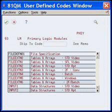
31.4 Viewing the Logic Module Index
The system allows multiple logic modules for each subroutine. Depending on the type of program in which you use the subroutine, the same subroutine can appear differently.
You can review the logic modules on the User Defined Codes window.
To view the logic module index
From Model Program Design Menu (G9361), under LOGIC MODULES, choose Index
Figure 31-1 User Defined Codes Window screen
Description of "Figure 31-1 User Defined Codes Window screen"
31.5 Viewing Logic Module Cross Reference
The Logic Module Cross Reference allows you to determine which program types use a particular logic module.
To view the logic module cross reference
From Model Program Design Menu (G9361), under LOGIC MODULES, choose Cross Reference
Enter a primary logic module name.
Figure 31-2 Cross Reference (View Logic) screen
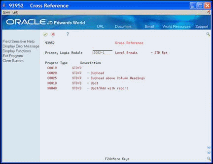
Description of "Figure 31-2 Cross Reference (View Logic) screen"
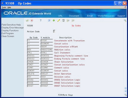
31.6 Viewing Logic Module Op Codes
-
Right column displays the x-module that the system launches to generate the source code.
If PDL does not generate source code, the Operation Code to Logic Module X-Ref file (F93108) might have been accidently cleared.
To view the logic module op codes
From Model Program Design Menu (G9361), under LOGIC MODULES, choose Op Codes
31.7 Maintaining the Logic Module File
The following programs do not appear on a menu and you must access these programs manually.
Caution:
Use extreme caution when using these programs.31.7.1 Resequence Logic Module
Use this program when you need to add several lines to a logic module and resequence the line numbers. If you add or change lines in a logic module, you must manually change or add the serial numbers for the logic module or run this program. The Resequence Master Source program (93998) launches a program to resequence an existing logic module.
Normally, you create and incorporate a new logic module into a new program type. You use the new program type and delete the old program type when there are no longer programs with that program type with a CAP status of Y.
CALL P93998 PARM (logic module name).
31.7.2 Remove Logic Module
You use this program when you no longer use a logic module and want to reduce the amount of source code in the F93001 file. The Remove Logic Module program (P93999) removes lines from F93001 and launches a program to remove an existing logic module.
You must ensure that there are no programs with a CAP status of Y that use a program type with this logic module.
CALL P93999 PARM(logic module name).
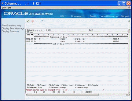
31.8 Creating or Modifying Logic Modules
The Create/Modify screen allows you to review only the logic module you want, otherwise all 12,000 lines of code display because the F93001 is a single member file.
You can choose Field Sensitive Help to access a list of logic modules, UDC 93/LM.
When the system accesses the code, it performs three steps:
-
Creates a work file in QTEMP/F93001WRK.
-
Adds a member to F93001WRK.
-
Clears the member in F93001WRK.
You can exit the code without saving your changes.
To create or modify logic modules
From Model Program Design Menu (G9361), under LOGIC MODULES, choose Create/Modify
-
Figure 31-4 Create/Modify (Logic Modules) screen
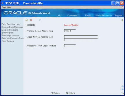
Description of "Figure 31-4 Create/Modify (Logic Modules) screen"
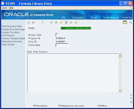
31.9 Creating or Modifying Formula Library Entry
When you choose this menu selection, the system preloads the screen with the keys for entering a formula.
Alternatively, you also access this screen through the Detailed Programming Facility to enter PDL.
To create or modify the formula library entry
From Model Program Design Menu (G9361), under LOGIC MODULES, choose Formula Library Entry
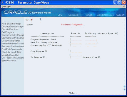
31.10 Copying or Moving Program Specifications
The Parameter Copy/Move program allows you to copy the following from one library to another or from one program ID to another:
-
Program Generator specifications
-
Data dictionary glossary (program purpose)
-
DREAM Writer processing options
Alternatively, you can enter 3 in the Option field on Software Versions Repository to copy Program Generator specifications within a library.
To copy or move program specifications
From Model Program Design Menu (G9361), under OTHER TOOLS, choose Parameter Copy/Move
On Parameter Copy/Move complete the following fields:
-
Program Generator Specs
-
Data Dictionary
-
Processing Option
-
From Program ID
-
To Program ID
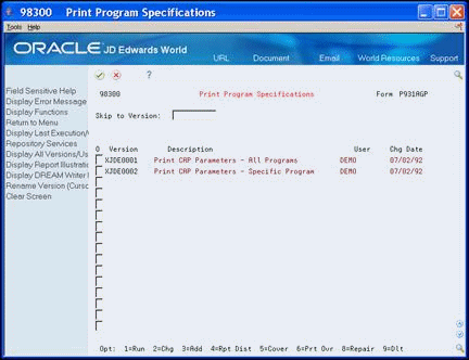
31.11 Printing Program Generator Specifications
Use the Print Program Specifications program to print the program specifications. You must use a logical file.
If the print job ends abnormally, review the Additional Parameters screen of the DREAM Writer and ensure that the File Output Type field is set to a Logical File and not Open Query.
To print program generator specifications
From Model Program Design Menu (G9361), under OTHER TOOLS, choose Print Program Specifications
Copy the appropriate version and change it to print the version of the specifications you want.
Figure 31-8 Print Program Specifications screen
Description of "Figure 31-8 Print Program Specifications screen"
31.12 Reviewing Source Modifications
The Review Source Modifications program displays the source code that a user adds manually through the Source Entry Utility. You view the Pxxxxx member in the Additional Help/Modifications Master file (F93002).
The lines of code are the result of the MPxxxxx job that runs and compares the before image of the source code with the source code after the user makes changes and stores the code in the Pxxxxx member in the F93002.
To review source modifications
From Model Program Design Menu (G9361), under OTHER TOOLS, choose Review Source Modifications
Alternatively, you can enter 30 in the Option field on Software Versions Repository to access Review Source Modifications screen.
-
On the Review Source Modifications screen, locate the program.
-
Enter 30 in the Option field to view source code modifications.
Figure 31-9 Review Source Code Modifications screen
Description of "Figure 31-9 Review Source Code Modifications screen"
31.13 Using Program Generator Updates
The both of the Generator Updates merge JD Edwards World updates for the Program Generator.
The system uses these programs during a PTF install.
To use program generator updates
From Model Program Design Menu (G9361), choose Generator Updates From Generator Updates (G9366), choose the appropriate Compare/Update
31.14 Using CASE Specifications Inquiry
The CASE Specifications Inquiry allows you to view the programs you design using the JD Edwards World CASE Tools. You can modify and delete CASE Specifications using this utility as well as access the source code in the Software Versions Repository.
To use CASE specifications inquiry
From Model Program Design Menu (G9361), under OTHER TOOLS, choose Case Specifications Inquiry
-
On CASE Specifications Inquiry, complete any of the following fields:
-
Program ID
-
System Code
-
CAP Status
-
Program Type
The system displays the records that meet your search criteria.
-
-
Complete the following field:
-
Option
-
Figure 31-10 CASE Specifications Inquiry screen
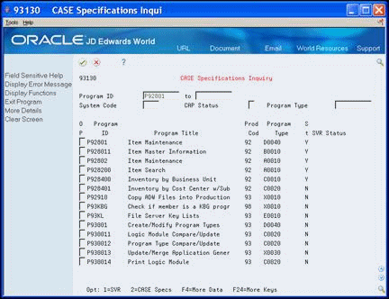
Description of "Figure 31-10 CASE Specifications Inquiry screen"