| Skip Navigation Links | |
| Exit Print View | |

|
Managing Oracle Solaris 11.1 Network Performance Oracle Solaris 11.1 Information Library |
| Skip Navigation Links | |
| Exit Print View | |

|
Managing Oracle Solaris 11.1 Network Performance Oracle Solaris 11.1 Information Library |
1. Introduction to Network Performance Management
How to Plan a VLAN Configuration
How to Configure VLANs Over a Link Aggregation
How to Configure VLANs on a Legacy Device
Use Case: Combining Link Aggregations and VLAN Configurations
4. Administering Bridged Networks (Tasks)
7. Exchanging Network Connectivity Information With LLDP
8. Working With Data Center Bridging Features in Oracle Solaris
9. Edge Virtual Bridging in Oracle Solaris
10. Integrated Load Balancer (Overview)
11. Configuring Integrated Load Balancer
12. Managing Integrated Load Balancer
13. Virtual Router Redundancy Protocol (Overview)
A. Link Aggregation Types: Feature Comparison
A virtual local area network (VLAN) is a subdivision of a local area network at the datalink layer of the protocol stack. You can create VLANs for local area networks that use switch technology. By assigning groups of users to VLANs, you can improve network administration and security for the entire local network. You can also assign interfaces on the same system to different VLANs.
The following sections provide a brief overview of VLANs.
Consider dividing your local network into VLANs if you need to do the following:
Create a logical division of workgroups.
For example, suppose all hosts on a floor of a building are connected on one switched-based local network. You could create a separate VLAN for each workgroup on the floor.
Enforce differing security policies for the workgroups.
For example, the security requirements of a Finance department and an Information Technology department are quite different. If systems for both departments share the same local network, you could create a separate VLAN for each department. Then, you could enforce the appropriate security policy on a per-VLAN basis.
Split workgroups into manageable broadcast domains.
The use of VLANs reduces the size of broadcast domains and improves network efficiency.
VLANs demonstrate the advantage of using generic or customized names. In previous releases, the VLAN was identified by the physical point of attachment (PPA) that required combining the hardware-based name of the datalink and the VLAN ID. In Oracle Solaris 11, you can select a more meaningful name to identify the VLAN. The name must conform to the rules for naming datalinks that are provided in Rules for Valid Link Names in Introduction to Oracle Solaris 11 Networking. Thus, a VLAN can be assigned the name sales0 or marketing1, for example.
VLAN names work in conjunction with VLAN IDs. Each VLAN in a local area network is identified by a VLAN ID, also known as a VLAN tag. The VLAN ID is assigned during VLAN configuration. When you configure switches to support VLANs, you need to assign a VLAN ID to each port. The VLAN ID on the port must be the same as the VLAN ID assigned to the interface that connects to the port.
The use of customized names and VLAN IDs is shown in the following section.
Switched LAN technology enables you to organize the systems on a local network into VLANs. Before you can divide a local network into VLANs, you must obtain switches that support VLAN technology. You can configure all ports on a switch to serve a single VLAN or multiple VLANs, depending on the VLAN topology design. Each switch manufacturer has different procedures for configuring the ports on a switch.
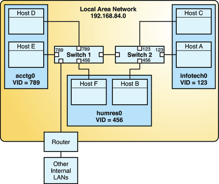
The following figure shows a local area network that has been divided into three VLANs.
Figure 3-1 Local Area Network With Three VLANs

In Figure 3-1, the LAN has the subnet address 192.168.84.0. This LAN is subdivided into three VLANs to correspond with three workgroups:
acctg0 with VLAN ID 789 – Accounting group. This group owns Host D and Host E.
humres0 with VLAN ID 456 – Human Resources group. This group owns Host B and Host F.
infotech0 with VLAN ID 123 – Information Technology group. This group owns Host A and Host C.
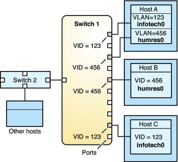
A variation of Figure 3-1 is shown in Figure 3-2 where only one switch is used, and multiple hosts belonging to different VLANs connect to that single switch.
Figure 3-2 Switch Configuration for a Network with VLANs

In Figure 3-2, Host A and Host C belong to the Information Technology VLAN with the VLAN ID 123. Thus, one of Host A's interface is configured with the VLAN ID 123. This interface connects to Port 1 on Switch 1, which is also configured with the VLAN ID 123. Host B is a member of the Human Resources VLAN with the VLAN ID 456. Host B's interface connects to Port 5 on Switch 1, which is configured with the VLAN ID 456. Finally, the interface of Host C is configured with the VLAN ID 123. The interface connects to Port 9 on Switch 1. Port 9 is also configured with the VLAN ID 123.
Figure 3-2 also shows that a single host can belong to multiple VLANs. For example, Host A has two VLANs configured over the host's interface. The second VLAN is configured with the VLAN ID 456 and is connected to Port 3 which is also configured with the VLAN ID 456. Thus, Host A is a member of both the infotech0 and the humres0 VLANs.
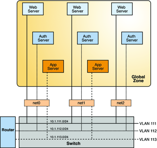
You can configure multiple virtual networks within a single network unit such as a switch by combining VLANs and Oracle Solaris Zones. Consider the following illustration of a system with three physical network cards net0, net1, and net2.
Figure 3-3 System With Multiple VLANs

Without VLANs, you would configure different systems to perform specific functions and connect these systems to separate networks. For example, web servers would be connected to one LAN, authentication servers to another LAN, and application servers to a third LAN. With VLANs and zones, you can collapse all eight systems and configure them as zones in a single system. Then you use VLAN IDs to assign a VLAN to each set of zones that performs the same functions. The information provided in the figure can be tabulated as follows.
|
To create the configuration shown in the figure, refer to Example 3-1.