| Skip Navigation Links | |
| Exit Print View | |

|
Oracle Solaris Cluster Concepts Guide Oracle Solaris Cluster 4.1 |
| Skip Navigation Links | |
| Exit Print View | |

|
Oracle Solaris Cluster Concepts Guide Oracle Solaris Cluster 4.1 |
2. Key Concepts for Hardware Service Providers
3. Key Concepts for System Administrators and Application Developers
Device IDs and DID Pseudo Driver
Cluster Configuration Repository (CCR)
Local and Global Namespaces Example
Using the cldevice Command to Monitor and Administer Disk Paths
Using the clnode set Command to Manage Disk Path Failure
Adhering to Quorum Device Requirements
Adhering to Quorum Device Best Practices
Recommended Quorum Configurations
Quorum in Two-Node Configurations
Quorum in Greater Than Two-Node Configurations
Characteristics of Scalable Services
Data Service API and Data Service Development Library API
Using the Cluster Interconnect for Data Service Traffic
Resources, Resource Groups, and Resource Types
Resource and Resource Group States and Settings
Resource and Resource Group Properties
Support for Oracle Solaris Zones
Support for Zones on Cluster Nodes Through Oracle Solaris Cluster HA for Solaris Zones
Criteria for Using Oracle Solaris Cluster HA for Solaris Zones
Requirements for Using Oracle Solaris Cluster HA for Solaris Zones
Additional Information About Oracle Solaris Cluster HA for Solaris Zones
Data Service Project Configuration
Determining Requirements for Project Configuration
Setting Per-Process Virtual Memory Limits
Two-Node Cluster With Two Applications
Two-Node Cluster With Three Applications
Failover of Resource Group Only
Public Network Adapters and IP Network Multipathing
SPARC: Dynamic Reconfiguration Support
SPARC: Dynamic Reconfiguration General Description
SPARC: DR Clustering Considerations for CPU Devices
SPARC: DR Clustering Considerations for Memory
SPARC: DR Clustering Considerations for Disk and Tape Drives
SPARC: DR Clustering Considerations for Quorum Devices
SPARC: DR Clustering Considerations for Cluster Interconnect Interfaces
SPARC: DR Clustering Considerations for Public Network Interfaces
The term data service describes an application, such as Oracle iPlanet Web Server, that has been configured to run on a cluster rather than on a single server. Data services enable applications to become highly available and scalable services help prevent significant application interruption after any single failure within the cluster. A data service consists of an application, specialized Oracle Solaris Cluster configuration files, and Oracle Solaris Cluster management methods that control the following actions of the application:
Start
Stop
Monitor and take corrective measures
There are two types of data services: single-mastered (or failover) and multi-mastered (or parallel). Some multi-mastered data services, referred to as scalable services, are designed to take advantage of Oracle Solaris Cluster network load balancing when configured with a SharedAddress resource.
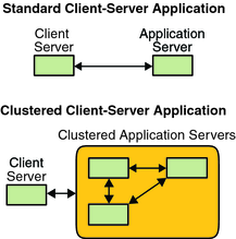
Figure 3-3 compares an application that runs on a single application server (the single-server model) to the same application running on a cluster (the clustered-server model). The only difference between the two configurations is that the clustered application might run faster and is more highly available.
Figure 3-3 Standard Compared to Clustered Client-Server Configuration

In the single-server model, you configure the application to access the server through a particular public network interface (a host name). The host name is associated with that physical server.
In the clustered-server model, the public network interface is a logical host name or a shared address. The term network resources is used to refer to both logical host names and shared addresses.
Some data services require you to specify either logical host names or shared addresses as the network interfaces. Logical host names and shared addresses are not always interchangeable. Other data services allow you to specify either logical host names or shared addresses. Refer to the installation and configuration for each data service for details about the type of interface you must specify.
A network resource is not associated with a specific physical server. A network resource can migrate between physical servers.
A network resource is initially associated with one node, the primary. If the primary fails, the network resource and the application resource fail over to a different cluster node (a secondary). When the network resource fails over, after a short delay, the application resource continues to run on the secondary.
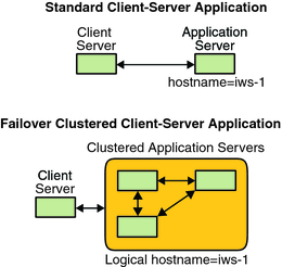
Figure 3-4 compares the single-server model with the clustered-server model. Note that in the clustered-server model, a network resource (logical host name, in this example) can move between two or more of the cluster nodes. The application is configured to use this logical host name in place of a host name that is associated with a particular server.
Figure 3-4 Fixed Host Name Compared to Logical Host Name

A shared address is also initially associated with one node. This node is called the global interface node. A shared address (known as the global interface) is used as the single network interface to the cluster.
The difference between the logical host name model and the scalable service model is that in the latter, each node also has the shared address actively configured on its loopback interface. This configuration enables multiple instances of a data service to be active on several nodes simultaneously. The term “scalable service” means that you can add more CPU power to the application by adding additional cluster nodes and the performance scales.
If the global interface node fails, the shared address can be started on another node that is also running an instance of the application (thereby making this other node the new global interface node). Or, the shared address can fail over to another cluster node that was not previously running the application.
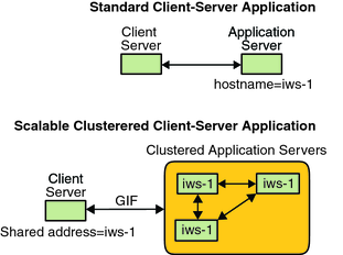
Figure 3-5 compares the single-server configuration with the clustered scalable service configuration. Note that in the scalable service configuration, the shared address is present on all nodes. The application is configured to use this shared address in place of a host name that is associated with a particular server. This scheme is similar to how a logical host name is used for a failover data service.
Figure 3-5 Fixed Host Name Compared to Shared Address

The Oracle Solaris Cluster software supplies a set of service management methods. These methods run under the control of the Resource Group Manager (RGM), which uses them to start, stop, and monitor the application on the cluster nodes. These methods, along with the cluster framework software and multihost devices, enable applications to become failover or scalable data services.
The RGM also manages resources in the cluster, including instances of an application and network resources (logical host names and shared addresses).
In addition to Oracle Solaris Cluster software-supplied methods, the Oracle Solaris Cluster software also supplies an API and several data service development tools. These tools enable application developers to develop the data service methods that are required to make other applications run as highly available data services with the Oracle Solaris Cluster software.
If the node on which the data service is running (the primary node) fails, the service is migrated to another working node without user intervention. Failover services use a failover resource group, which is a container for application instance resources and network resources (logical host names). Logical host names are IP addresses that can be configured on one node, and at a later time, automatically configured down on the original node and configured on another node.
For failover data services, application instances run only on a single node. If the fault monitor detects an error, it either attempts to restart the instance on the same node, or to start the instance on another node (failover). The outcome depends on how you have configured the data service.
The scalable data service has the potential for active instances on multiple nodes.
Scalable services use the following two resource groups:
A scalable resource group contains the application resources.
A failover resource group, which contains the network resources (shared addresses) on which the scalable service depends. A shared address is a network address. This network address can be bound by all scalable services that are running on nodes within the cluster. This shared address enables these scalable services to scale on those nodes. A cluster can have multiple shared addresses, and a service can be bound to multiple shared addresses.
A scalable resource group can be online on multiple nodes simultaneously. As a result, multiple instances of the service can be running at once. All scalable resource groups use load balancing. All nodes that host a scalable service use the same shared address to host the service. The failover resource group that hosts the shared address is online on only one node at a time.
Service requests enter the cluster through a single network interface (the global interface). These requests are distributed to the nodes, based on one of several predefined algorithms that are set by the load-balancing policy. The cluster can use the load-balancing policy to balance the service load between several nodes. Multiple global interfaces can exist on different nodes that host other shared addresses.
For scalable services, application instances run on several nodes simultaneously. If the node that hosts the global interface fails, the global interface fails over to another node. If an application instance that is running fails, the instance attempts to restart on the same node.
If an application instance cannot be restarted on the same node, and another unused node is configured to run the service, the service fails over to the unused node. Otherwise, the service continues to run on the remaining nodes, possibly causing a degradation of service throughput.
Note - TCP state for each application instance is kept on the node with the instance, not on the global interface node. Therefore, failure of the global interface node does not affect the connection.
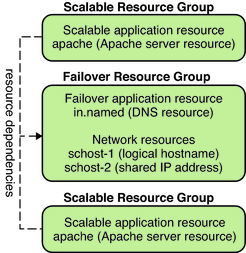
Figure 3-6 shows an example of failover and a scalable resource group and the dependencies that exist between them for scalable services. This example shows three resource groups. The failover resource group contains application resources for highly available DNS, and network resources used by both highly available DNS and highly available Apache Web Server. The scalable resource groups contain only application instances of the Apache Web Server. Note that all the Apache application resources are configured with resource dependencies on the network resource schost-2, which is a shared address (dashed lines).
Figure 3-6 Instances of Failover and Scalable Resource Groups

Load balancing improves performance of the scalable service, both in response time and in throughput. There are two classes of scalable data services.
A pure service is capable of having any of its instances respond to client requests. A sticky service is capable of having a client send requests to the same instance. Those requests are not redirected to other instances.
A pure service uses a weighted load-balancing policy. Under this load-balancing policy, client requests are by default uniformly distributed over the server instances in the cluster. The load is distributed among various nodes according to specified weight values. For example, in a three-node cluster, suppose that each node has the weight of 1. Each node services one third of the requests from any client on behalf of that service. The cluster administrator can change weights at any time with an administrative command.
The weighted load-balancing policy is set by using the LB_WEIGHTED value for the Load_balancing_weights property. If a weight for a node is not explicitly set, the weight for that node is set to 1 by default.
The weighted policy redirects a certain percentage of the traffic from clients to a particular node. Given X=weight and A=the total weights of all active nodes, an active node can expect approximately X/A of the total new connections to be directed to the active node. However, the total number of connections must be large enough. This policy does not address individual requests.
Note that the weighted policy is not round robin. A round-robin policy would always cause each request from a client to go to a different node. For example, the first request would go to node 1, the second request would go to node 2, and so on.
A sticky service has two flavors, ordinary sticky and wildcard sticky.
Sticky services enable concurrent application-level sessions over multiple TCP connections to share in-state memory (application session state).
Ordinary sticky services enable a client to share the state between multiple concurrent TCP connections. The client is said to be “sticky” toward that server instance that is listening on a single port.
The client is guaranteed that all requests go to the same server instance, provided that the following conditions are met:
The instance remains up and accessible.
The load-balancing policy is not changed while the service is online.
For example, a web browser on the client connects to a shared IP address on port 80 using three different TCP connections. However, the connections exchange cached session information between them at the service.
A generalization of a sticky policy extends to multiple scalable services that exchange session information in the background and at the same instance. When these services exchange session information in the background and at the same instance, the client is said to be “sticky” toward multiple server instances on the same node that is listening on different ports.
For example, a customer on an e-commerce web site fills a shopping cart with items by using HTTP on port 80. The customer then switches to SSL on port 443 to send secure data to pay by credit card for the items in the cart.
In the ordinary sticky policy, the set of ports is known at the time the application resources are configured. This policy is set by using the LB_STICKY value for the Load_balancing_policy resource property.
Wildcard sticky services use dynamically assigned port numbers, but still expect client requests to go to the same node. The client is “sticky wildcard” over pots that have the same IP address.
A good example of this policy is passive mode FTP. For example, a client connects to an FTP server on port 21. The server then instructs the client to connect back to a listener port server in the dynamic port range. All requests for this IP address are forwarded to the same node that the server informed the client through the control information.
The sticky-wildcard policy is a superset of the ordinary sticky policy. For a scalable service that is identified by the IP address, ports are assigned by the server (and are not known in advance). The ports might change. This policy is set by using the LB_STICKY_WILD value for the Load_balancing_policy resource property.
For each one of these sticky policies, the weighted load-balancing policy is in effect by default. Therefore, a client's initial request is directed to the instance that the load balancer dictates. After the client establishes an affinity for the node where the instance is running, future requests are conditionally directed to that instance. The node must be accessible and the load-balancing policy must not have changed.
Resource groups fail over from one node to another. When this failover occurs, the original secondary becomes the new primary. The failback settings specify the actions that occur when the original primary comes back online. The options are to have the original primary become the primary again (failback) or to allow the current primary to remain. You specify the option you want by using the Failback resource group property setting.
If the original node that hosts the resource group fails and reboots repeatedly, setting failback might result in reduced availability for the resource group.
Each Oracle Solaris Cluster data service supplies a fault monitor that periodically probes the data service to determine its health. A fault monitor verifies that the application daemon or daemons are running and that clients are being served. Based on the information that probes return, predefined actions such as restarting daemons or causing a failover can be initiated.