A Slot Mapping and Cartridge Locations
Cartridge Slot Addressing
Library slots are identified by library-module, side, row, column, where:
-
library-module is the module that contains the slot. Modules are numbered by starting from the base module (
1) and counting down. -
side identifies the magazine within the module either
LeftorRight. -
row is the row of the slot with in the magazine, numbered starting from the top of magazine(
1) and counting down. -
column is the column of the slot within the magazine, numbered starting from the handle side of the magazine, at the front of the library, and counting to the back.
Reserved Slots
The library can have a maximum of three reserved slots. Only the following slot addresses can be used as reserved slots (see "Determine the Required Number of Reserved System Slots"). Reserved slots do not have a SCSI element address.
-
1,Left,1,1 -
1,Left,2,1 -
1,Left,3,1
Drive, Mailslot, Power Supply, and Robot Addressing
Component locations are identified using the following addressing schemes:
| Component | SCSI Element Address | Physical addressing |
|---|---|---|
| Drives | Yes | module,top|bottom |
| Mailslot | Yes | slot number |
| Expanded Mailslot | Yes | module,side,row,column |
| Power Supply | No | module,top|bottom |
| Hand (Robot) | Yes | n/a |
SCSI Element Addressing
The following table shows the starting element address and the maximum number of each element type for a 15 module library.
Table A-1 Starting Element Address and Maximum Number of Elements
| Element Type | First Element Address | Maximum Number of Elements for an SL150 Library with 15 Modules and the Standard Mailslot Configuration | Maximum Number of Elements for an SL150 Library with 15 Modules and the Expanded Mailslot Configuration |
|---|---|---|---|
|
Hand |
0 |
1 |
1 |
|
Mailslot |
10 |
4 |
19 |
|
Drives |
500 |
30 |
30 |
|
Storage Slots |
1000 |
450 |
435 |
Example Library Configurations and Slot Maps
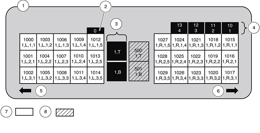
Illustration Legend:
1 - Module 1 (Base)
2 - Robot
3 - Power supplies
4 - Standard mailslots
5 - Left magazine front
6 - Right magazine front
7 - Storage slots
8 - Tape drives
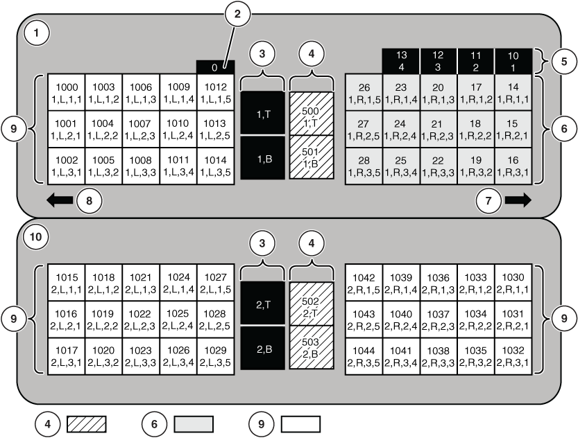
Illustration Legend:
1 - Module 1 (Base)
2 - Robot
3 - Power supplies
4 - Tape drives
5 - Standard mailslot
6 - Mailslot expansion
7 - Right magazine front
8 - Left magazine front
9 - Storage slots
10 - Module 2 (Expansion)
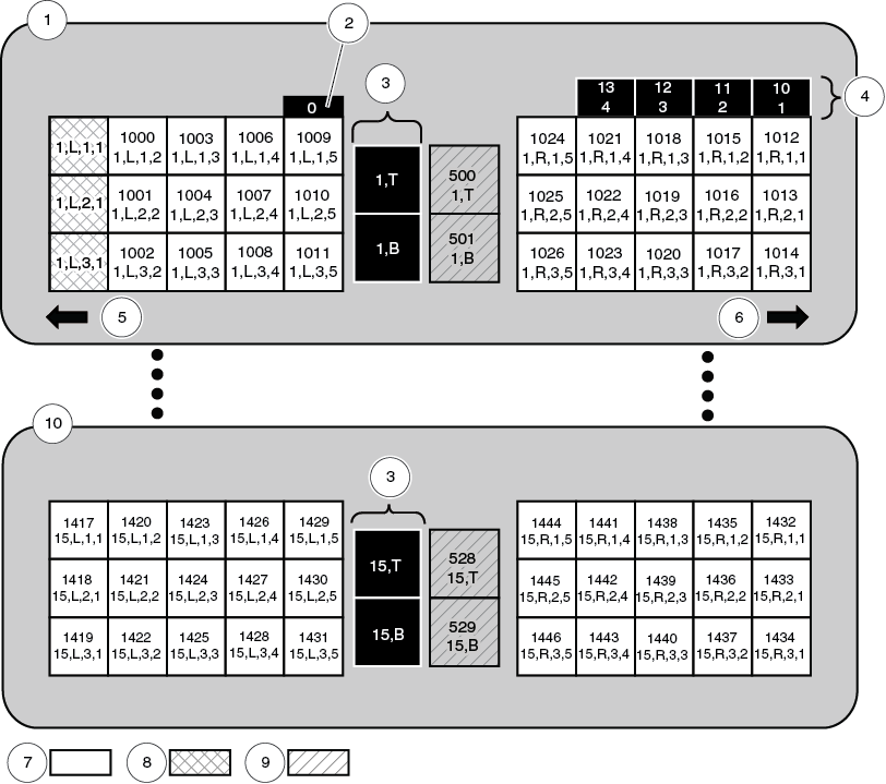
Illustration Legend:
1 - Module 1 (Base)
2 - Robot
3 - Power supplies
4 - Standard mailslots
5 - Left magazine front
6 - Right magazine front
7 - Storage slots
8 - Reserved slots (Configurable)
9 - Tape drives
10 - Module 15 (Expansion)


