10 Replacing Components (CRUs & FRUs)
Caution:
The robot, front control panel, and base module are critical to maintaining the product serial number and customer settings. When a replacement is needed, you may only replace one unique part during a single power down cycle.This chapter assumes you have isolated the issue and have replacement parts on hand. If you have not determined the problem, see "Troubleshoot the Library".
CRU Locations
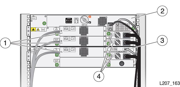
Illustration Legend:
- 1 - Tape Drive Tray
- 2 - Robot (in the Base Module)
- 3 - Module Controller (in the Expansion Module)
- 4 - Power Supply
Drive Tray Removal and Replacement
Warning:
Do not operate the library with open tape drive slot or power supply slots.

Illustration Legend:
- 1 - Drive Indicators
- 2 - Port Indicator (HP SAS and HP LTO-6 FC Drives)
- 3 - Encryption Indicator and IP Reset Switch (HP drives only)
- 4 - Thumbscrew (Drive Tray has Two Thumbscrews)
Remove the Drive Tray
IMPORTANT:
Removal of a bridged drive results in loss of host connectivity to the library.-
In the remote interface, select Library in the left menu. Right-click on the drive, and then select Remove Drive.
-
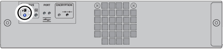
At the back of the library, locate the drive tray with the blue LED indicator (upper left corner).
-
Label and then disconnect the cables from the drive tray.
-
Loosen the two green thumbscrews on the drive tray. Grasp the drive tray, pull it out of the slot, and set it on a work surface.
Replace the Drive Tray
-
Replace the Drive Tray Task 1: Remove New Drive Tray from Package
-
Replace the Drive Tray Task 3: Verify the Library Recognized the New Drive Tray
Replace the Drive Tray Task 1: Remove New Drive Tray from Package
Caution:
Equipment damage. Do not touch the circuit card or static sensitive components. Follow accepted practices to prevent damage from ESD.-
Handle the drive tray by the rear corners (near the thumbscrews) and the bottom of the tray. Avoid contact with the top cover of the tape drive.
-
Remove the replacement drive tray from the shipping carton. Save the packaging materials to return the failed CRU.
Replace the Drive Tray Task 2: Replace the Drive Tray
-
Grasp the rear corners of the drive tray and guide it into the drive slot. Push the drive tray completely into the drive slot.
-
Verify that the indicators are active on the rear of the drive tray.
-
Tighten the thumbscrews. Ensure there is no tray movement in any direction.
-
Connect the interface cable(s) and Ethernet cable (if applicable) on the left side of the drive tray.
Replace the Drive Tray Task 3: Verify the Library Recognized the New Drive Tray
-
Confirm that the library recognizes the drive (Drives area of the SL150 remote interface). It can take some time for the indicators to show the drive is operational.
-
Make sure the drive port is enabled (view the Drive Properties and change drive settings if appropriate).
-
Identify the tape drive firmware version and upgrade if necessary (see "Update Library and Drive Firmware").
Remove a Drive Filler
You may need to remove a drive filler, if you are installing a new drive tray or need to gain access to the library. See "Remove a Tape Drive Filler"
Install a Drive Filler
-
Position the tape drive filler with the spring fingers facing up.
-
Grasp the captive screws and guide the filler into the tape drive slot.
-
Tighten both thumbscrews.
Power Supply Removal and Replacement

Illustration Legend:
- 1 - Power Supply Indicators
- 2 - Power Supply Latch
Remove the Power Supply
-
If the library only has one power supply, power off the library before proceeding (see "Power Off the Library").
-
Disconnect the power cord from the defective power supply.
-
Press the latch towards the left (toward the fan) to release the power supply.
-
Grasp the power supply by the handle, pull it out of the library, and set it aside.
Replace the Power Supply
-
Remove the power supply from the shipping carton.
-
Grasp the supply by the handle and support the bottom with your other hand.
-
Orient the power supply as shown in Figure 10-2 (oriented with LEDs on left).
-
Align the rear of the supply with the module slot. Push the supply fully into the module slot. Make sure the power supply is secured in the module slot.
-
Connect the power cord to the power supply receptacle.
-
Verify that the OK indicator is active on the power supply. If not, continue to "Validate the Component Installation".
Remove a Power Supply Filler
You may need to remove a power supply filler if you are adding a new power supply or replacing other CRUs. For instructions, see "Remove the Power Supply Filler".
Install a Power Supply Filler
-
Position the filler with the spring fingers facing up.
-
Insert the tabs on the right side of the filler into the power supply slot until the notch is near the module frame.
-
Seat the filler notch against the module frame edge.
-
Push the left side of the filler into the power supply slot.
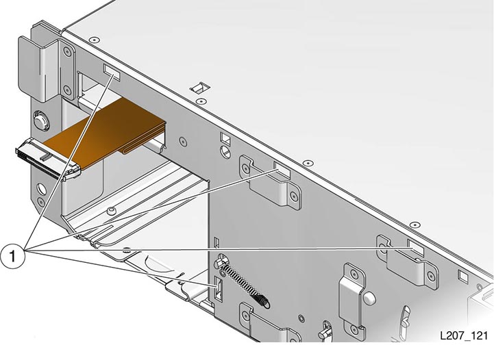
Front Control Panel Removal and Replacement
The front control panel is located at the front of the base module.
Caution:
The front control panel maintains the product serial number and customer settings. After installing the panel, you must power-cycle the library before installing any other component.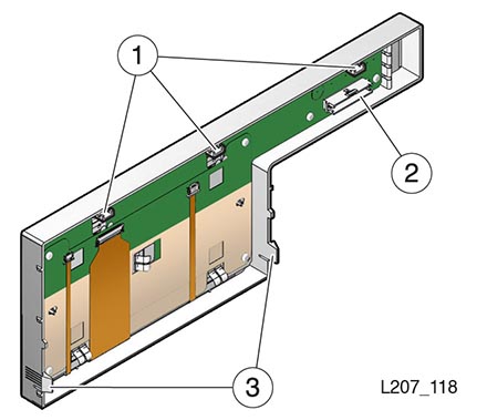
Illustration Legend:
- 1 - Tabs
- 2 - Jack
- 3 - Latches
Remove the Front Control Panel
-
Power down the library (see "Power Off the Library").
-
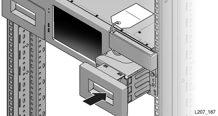
Remove both cartridge magazines from the base module (see "Load the Magazines Task 1: Unlock and Remove the Magazines").
-
Press the latch inside each magazine bay inner wall and pull the bottom edge of the panel away from the module until the panel unlatches (see image below).

-
Free the tabs on the top edge of the panel from the module.
-
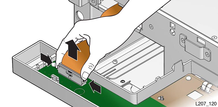
Rotate the top edge of the panel away from the top of the module about 90 degrees and hold the panel in this position with one hand.
-
Disconnect the ribbon cable plug from the jack located on the circuit card.
-
Set the panel CRU on the anti-static mat.
Replace the Front Control Panel
Caution:
ESD damage. Do not touch any exposed electronic components, cables, or contacts.-
Remove the replacement front control panel from its packaging.
-
Grasp the panel by the plastic housing and raise it to the base module.
-
Attach the cable to the circuit card jack at the back of the panel. Make sure the connector is flush with the jack.
-
Insert the tabs on the top edge of the panel into the base module slots (see image below for slot locations).
-
Rotate the front control panel down and press the bottom edge into the base module slots. The panel snaps in place.
-
Replace both cartridge magazines. Lock the magazines and audit the library (see "Load the Magazines Task 4: Locking the Magazines and Auditing the Library").
-
Power-cycle the library. Follow the power on procedures (see "Validate the Component Installation").
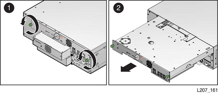
Module Controller Removal and Replacement
The module controller is located in the upper right corner of the expansion module as viewed from the rear of the library (see "CRU Locations"). The module controller obtains power from the expansion cable connected to a Module Output port on the base module.
Remove the Module Controller
Note:
Be aware of ESD (see "Electrostatic Discharge").-
Power down the library (see "Power Off the Library").
-
Disconnect the expansion cable plug from the input port on the module controller.
-
Disconnect the expansion cable plug from the output port on the module controller of a library with a tape capacity of greater than 300 tapes. This action applies to Module 6 through Module 10.
-
Squeeze the latch sections together.
-
Extend the latch fully away from the module controller.
-
Pull the controller card out of the module slot.
-
Set the module controller on the anti-static work surface.
Replace the Module Controller
Caution:
ESD damage. Do not touch any electronic components or electrical contacts.-
Remove the replacement module controller from the ESD packaging.
-
Grasp the module controller without touching components or electrical contacts, and open the retaining latch.
-
Insert the module controller, component side up, into the module slot.
-
Seat the latch in the slot to secure the module controller.
-
Connect the expansion cable input plug to the module controller input port.
-
Connect the expansion cable output plug to the module controller output port. This applies to libraries with tape capacity greater than 300 tapes (Module 6 through Module 10). You must remove the dust cover from the output port.

-
Insert the failed module controller into the ESD packaging.
-
Follow the power on procedures (see "Validate the Component Installation").
Robot Module Removal and Replacement
The robot module is located at the top of the base module (see "CRU Locations"). The robot must be parked in the base module, the robot lock engaged, and the thumbscrews loosened before attempting to remove the robot module.
Caution:
The robot maintains the product serial number and customer settings. After installing the robot, you must power-cycle the library before installing any other component.Remove the Robot
Caution:
You must park and latch the robot before attempting to remove it.Remove the Robot Task 1: Park and Lock the Robot
-
Power down the library with the ”to prepare the robot for removal” option enabled (see "Controlled Power-Down from the Interface").
If the robot cannot be parked by using the power-down procedure, perform the manual robot extraction procedure (see "Manually Retract the Robot").
-
Remove the top drive tray or drive filler from the base module.
-
Look through the drive slot and locate the position of the robot.
-
Verify the robot is fully seated against the ceiling of the library.
Repeat the parking procedure if necessary to make sure the robot is secured in the proper position.
-
Lock the robot (see "Lock the Robot").
-
Replace the top drive or drive filler in the base module.
Remove the Robot Task 2: Slide Robot CRU Out of Base Module
Note:
The robot CRU weighs approximately 5 kg (11 pounds).-
Label the cables connected to the robot CRU as necessary.
-
Disconnect all cables attached to the robot CRU.
-
Loosen the robot module thumbscrews.
-
Grasp the robot module thumbscrews and pull the robot approximately 25cm (10 inches) out of the base module.
-
Reposition your hands near the center of the extended robot.
-
Pull the robot completely out of the base module, and set it on the anti-static work surface.
-
Proceed to "Replace the Robot".
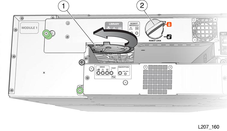
Manually Retract the Robot
Only use this procedure if you could not park the robot by using the power-down procedure.
-
Remove the top drive tray from the base module (see "Drive Tray Removal and Replacement").
-
Locate the bullwheel gear inside the library and above the top drive slot (see Figure 10-4).
-
Look through the drive slot and locate the position of the robot.
-
Turn the gear with your thumb to raise the robot, hold the gear in position with a finger, reposition your thumb, and turn the gear. Repeat as necessary until the robot is at the top of the base module.
If the robot does not retract, disengage it (see "Manually Disengage the Robot").
-
Hold the bullwheel gear with the robot fully raised until you lock the robot.
-
Return to Step 5 of 0, "Remove the Robot Task 1: Park and Lock the Robot" and continue through the last step of robot removal (see 0, "Remove the Robot Task 2: Slide Robot CRU Out of Base Module").
Illustration Legend:
- 1 - Bullwheel Gear
- 2 - Robot Lock (Improved Design)
Manually Disengage the Robot
Caution:
Perform this procedure only if either the library power down (Step 1 of "Remove the Robot Task 1: Park and Lock the Robot") or "Manually Retract the Robot" does not work. This procedure damages the robot assembly.Manually Disengage the Robot Task 1: Cut Cables
-
Make sure the library is powered down.
-
Remove all tape drives from the base module.
-
Cut the accordion cable (folded ribbon cable).
-
Reach into the library and cut both rear suspension cables.
-
Cut the front suspension cables. The Z platform should settle to the floor of the bottom module.
Manually Disengage the Robot Task 2: Remove the Robot CRU
-
Loosen the robot module thumbscrews.
-
Grasp the robot module thumbscrews and pull the robot approximately 254 mm (10 inches) out of the base module.
-
Reposition your hands along the sides of the extended robot and close to the base module.
-
Pull the robot completely out of the base module, and set it aside.
Manually Disengage the Robot Task 3: Remove the Z Platform
-
Remove the cartridge magazines from the base module.
-
Remove cartridge magazines from expansion modules until you locate the Z platform.
Note:
You can also perform this procedure at the rear of the library by removing the tape drives or drive fillers from the modules, and reaching through the drive openings. -
Grasp the platform by reaching through either the magazine or tape drive openings.
-
Raise the platform by hand to the top of the base module.
-
Push the platform through the robot CRU opening at the rear of the base module far enough so that it does not slip back inside the library.
-
Go to the back of the library, grasp the robot CRU, and remove it from the library.
Manually Disengage the Robot Task 4: Clean Up
-
Inspect the library floor and remove any debris resulting from the broken robot.
-
Replace all cartridge magazines and tape drives removed during this procedure.
-
Follow the replace robot procedures (see "Replace the Robot").
Replace the Robot
Replace the Robot Task 1: Reinsert the Robot CRU and Unlock the Robot
-
Remove the replacement robot from its shipping carton, and set it on the anti-static mat. Save the packaging materials for the return of the failed CRU.
-
Grasp the robot near the center with the thumbscrews facing you.
-
Insert the robot into the base module.
-
Push the robot fully into the module.
-
Tighten the thumbscrews on each side of the robot CRU.
-
Unlock the robot (see "Unlock the Robot").
Replace the Robot Task 2: Cabling
-
Plug the expansion cable for Module 2 through Module 10 into the appropriate base module connector.
For example, connect the output plug of the expansion cable to Port 2 on the robot CRU and the input plug of the cable to the Module 2 controller input port.
Note:
The initial design of the expansion cable did not have plug labels. -
Plug the Ethernet cables into the appropriate Net Mgt ports.
-
Follow the power on procedures (see "Validate the Component Installation").
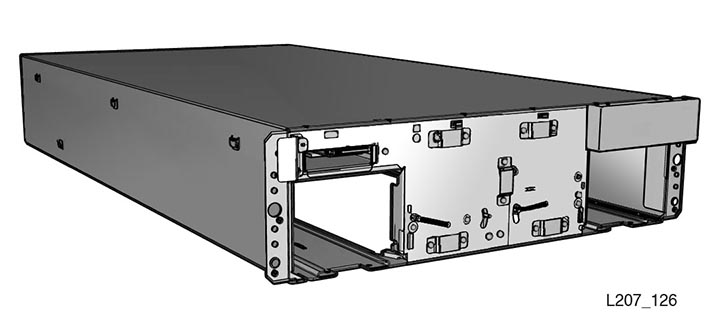
Expansion Module Chassis Removal and Replacement (FRU)
Note:
The expansion module is a field-replaceable unit (FRU) and must be serviced by an Oracle service person.You must transfer cartridge magazines, tape drives, tape drive fillers, power supplies, power supply fillers, and the module controller from the failed module to the FRU, as applicable. You might need to remove operational modules to access the defective one.
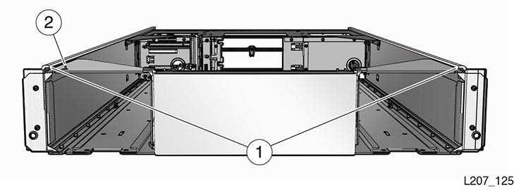
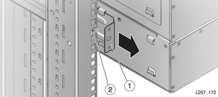
Illustration Legend:
1 - Flange
2 - Tab
Remove an Expansion Module
-
Remove Expansion Task 1: Power Down, Lock the Robot, and Remove Magazines
-
Remove Expansion Task 2: Remove the Floor, Cables, and Cords
-
Remove Expansion Task 3: Remove Operational Expansion Modules Below the Defective Module
-
Remove Expansion Task 4: Remove Components from the Defective Module
Remove Expansion Task 1: Power Down, Lock the Robot, and Remove Magazines
Caution:
You must park and lock the robot before attempting to remove an expansion module.-
Power down the library with the option enabled to prepare the robot for removal (see "Controlled Power-Down from the Interface").
-
Perform the robot park and lock instructions (see "Remove the Robot Task 1: Park and Lock the Robot").
-
Remove the magazines from the defective module. Remove the magazines from all modules below it, and remove the magazines from the module directly above it (see "Mount the Base Module Task 2: Remove the Cartridge Magazine with the Hex Key").
Remove Expansion Task 2: Remove the Floor, Cables, and Cords
-
Grasp the library floor at the thumb-holds within the magazine openings.
-
Pull the floor out from the front of the module.
Note:
If the floor does not move, reach through the magazine opening and push down on the floor behind the touch screen panel to unseat the floor locks. Pull the floor forward with your other hand. -
Disconnect the expansion cable plug(s) from the port(s) at each affected expansion module controller. Module 6 through Module 10 could have both ports connected.
Note:
The original design of the expansion controller had a single port only. -
Open the hook and loop strap, extract all cables and cords, then remove the hook and loop strap (open the plunger on the plastic rivet).
-
Disconnect the power supply cord.
-
Disconnect the drive interface and Ethernet cables, as applicable.
Remove Expansion Task 3: Remove Operational Expansion Modules Below the Defective Module
Warning:
Expansion modules weigh about 19.9 kg (43.9 pounds) with two cartridge magazines, 30 tape cartridges, two tape drives, and two power supplies.
-
(Optional) Remove tape drives and power supplies to lighten the weight of the expansion module (see, as necessary, "Drive Tray Removal and Replacement" and "Power Supply Removal and Replacement").
-
Remove the Phillips screws securing the expansion module to the front of the rack.
-
Grasp the module, pull it forward until the break in the flange is visible, lower the front of the module, pull it free from the module above it, and away from the rack.
-
Set the module down and away from the front of the rack.
-
Remove the Phillips screws and rear rails from the module. Leave the clip nut in place (see Figure 10-6).
-
Repeat 0 until you have removed all modules below the failed module.
Illustration Legend:
- 1 - Rear Rail
- 2 - Clip Nut
Replace the Expansion FRU Chassis
-
Replace Expansion Task 2: Install CRUs, Fillers, and Magazines in Replaced Module
-
Replace Expansion Task 3: Install the Remaining Expansion Modules
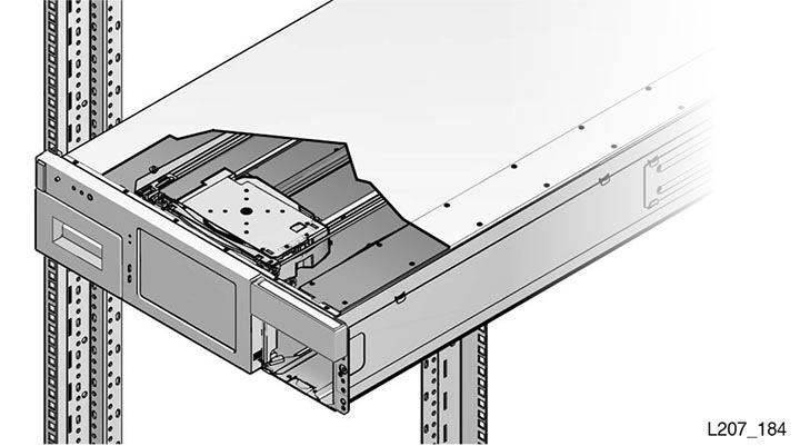
Replace Expansion Task 1: Install the Chassis
-
Grasp the expansion module chassis by the sides and remove it from the shipping carton.
-
Remove the magazines from the expansion module (see "Prepare the Expansion Module by Removing the Cartridge Magazines").
-
If this will be the bottom module of the library, install the library floor now (see "Install the Floor in the Bottom Expansion Module").
-
Mount the module (see "Mount the Expansion Module").
-
Install the rails (see "Install the Rear Rails for the Expansion Module").
-
Secure the module (see "Secure the Expansion Module to the Front Rack Stile").
Replace Expansion Task 2: Install CRUs, Fillers, and Magazines in Replaced Module
Cables and cords are connected as part of CRU installation.
-
Install the module controller (see "Replace the Module Controller").
Tip:
When the library capacity is more than 300 cartridges, you will not connect the output port for Module 6 through Module 10 now. You connect the port when installing Module 11 through Module 15. -
Install the tape drive assembly (see "Replace the Drive Tray").
-
Install the tape drive filler (see "Install a Drive Filler").
-
Install the power supply (see "Replace the Power Supply").
-
Install the power supply filler (see "Install a Power Supply Filler").
-
Insert the cartridge magazines.
Replace Expansion Task 3: Install the Remaining Expansion Modules
-
Locate the next expansion module for installation (refer to the module number label on the back of the module).
-
Repeat the installation tasks until all expansion modules and CRUs are installed (refer to 0 and 0).
-
Make sure you have installed the floor in the bottom module (see "Install the Floor in the Bottom Expansion Module").
Replace Expansion Task 4: Finishing Touches
-
Secure the hook and loop strap to the replaced expansion module (close the plunger of the rivet).
-
Align, dress, and secure cables in the hook and loop straps.
-
Follow the power on procedures (see "Validate the Component Installation").
Base Module (Module 1) Chassis Removal and Replacement
Note:
The base module is a field-replaceable unit (FRU) and must be serviced by an Oracle service person.You must transfer the cartridge magazines, front control panel, tape drive(s), tape drive filler, power supply, power supply filler, and the robot from the defective base module to the FRU.
Caution:
The robot, front control panel, and base module chassis are critical to maintaining the product serial number and customer settings. When a replacement is needed, you may replace only one unique device during a single power-down cycle.If the library has expansion modules, remove all of the expansion modules to access the defective base module.
Remove the Base Module Chassis
-
Remove Base Task 1: Lock the Robot and Remove Expansion Modules
-
Remove Base Task 2: Remove Module and Remove Parts for Reuse
Remove Base Task 1: Lock the Robot and Remove Expansion Modules
-
Park and lock the robot (see "Remove the Robot Task 1: Park and Lock the Robot").
-
Remove all modules below the base module (see "Remove an Expansion Module").
Remove Base Task 2: Remove Module and Remove Parts for Reuse
-
Remove the following applicable parts from the Base module:
-
Remove the screws securing the base module to the front of the rack.
Warning:
The base module weighs approximately 12.8 kg (28.3 pounds) without magazines, tape drives, power supplies, or the robot CRU. A best practice is to use two persons to lift the unit.
-
Extract the module from the rack.
Replace the Base Module Chassis
-
Replace Base Task 2: Install the Base Module CRUs and Expansion Modules
-
Replace Base Task 3: Reinstall Magazines and Dress the Cables
Replace Base Task 1: Install the Base Module FRU
-
Grasp the base module chassis by the sides and remove it from the shipping carton.
-
If there are no expansion modules for this library, install the floor in the base module (see "Install the Floor in the Bottom Expansion Module").
-
Mount the base module (see "Mount the Base Module").
Replace Base Task 2: Install the Base Module CRUs and Expansion Modules
-
Reinstall the base module components.
-
Reinstall the expansion modules (see "Replace the Expansion FRU Chassis"). Make sure to install the floor in the bottom module.
-
Re-cable the expansion modules. Connect the specific base module port to the controller card port of the associated expansion module. See "Cable the Library Task 1: Cable the Expansion Modules" for details.
Replace Base Task 3: Reinstall Magazines and Dress the Cables
-
Install cartridge magazines in all modules (see "Load the Magazines Task 4: Locking the Magazines and Auditing the Library").
-
Align and dress the cables. Secure the cables in the hook and loop straps, if applicable.
Illustration Legend:
- 1 - Tape Drive With Fibre Channel Cable
- 2 - Expansion Module Cable
- 3 - Ethernet Cable
- 4 - Power Supply Cord
- 5 - Tape Drive With SAS Cable
-
Connect the power cord to each installed power supply.
-
Follow the power on procedures (see "Validate the Component Installation").

Validate the Component Installation
-
Power on the library (see "Power On the Library").
-
Check the OK indicators on all CRUs.
-
Verify that the library health state is operational from either the touch screen or the remote interface (see "View the Library State").
If the health state is degraded or failed, see "Troubleshoot the Library" to assist with resolving the problem.
-
Perform an operational check of replaced CRUs, as applicable:
-
Front Panel — Test the panel for general operation (locate light, touch screen, open the mailslot, and so forth).
-
Module Controller — Confirm that the library recognizes the module controller (Modules area of the touch screen or Library area of the SL150 remote interface).
-
-
Run the offline self tests from the remote interface (see "Run a Self-Test").
-
Set the library to the online state (see "Place the Library Online and Offline") and log out of the remote interface.
-
Run host application commands to ensure that the library and drive applications are synchronized. See your host tape application documentation for guidance.
Return CRU Components to Oracle
You should only replace a single CRU at a time. Keep the original CRU until the correct CRU is identified as faulty.
Return the robot and tape drive tray CRUs to Oracle. Instructions should have been provided regarding the process to return the specific CRU.
Dispose of all other CRUs or recycle them, as appropriate.
Lock the Robot for Reshipment within Rack
Use the following instructions if you are shipping the SL150 after installing it into a rack.
Caution:
Improper installation of the lock could cause catastrophic failure during shipment.Power Down the Library and Verify Robot Position
-
Power down the library with the ”to prepare the robot for removal” option enabled (see "Controlled Power-Down from the Interface").
-
Lock the robot (see "Lock the Robot").
-
Remove the right cartridge magazine from the base module (see "Mount the Base Module Task 2: Remove the Cartridge Magazine with the Hex Key" if necessary).
-
Make sure the robot has positioned the hand against the ceiling and front face of the library (see image below).
Install the Shipping Clip
-
Verify the robot is in position (see Power Down the Library and Verify Robot Position).
-
Grasp the shipping clip and reach through the cartridge magazine opening.
-
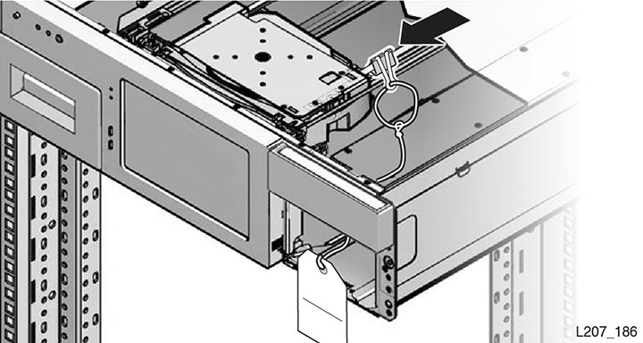
Open the shipping clip and install it over the 7 mm steel shaft behind the hand assembly (see image below).
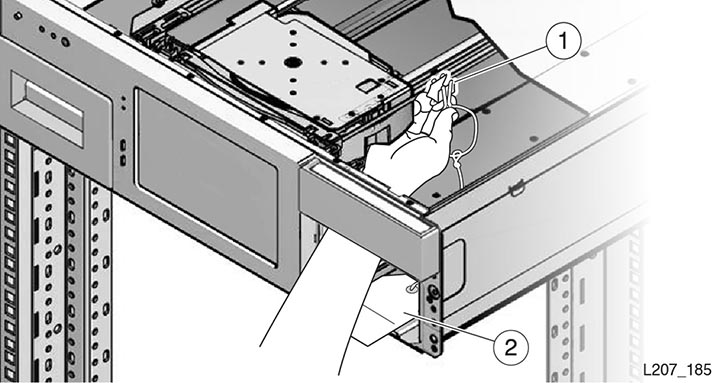
Illustration Legend:
- 1 - Opened Shipping Clip
- 2 - Instruction Tag
-
Squeeze the clip to reduce the clamping force on the shaft and slide the clip toward the hand assembly (see image below). The hand will be contained between the front wall and the clip.
-
Guide the instruction tag out of the cartridge magazine slot. Route the string and instruction tag between the mailslot and right side of the front control panel and set it on top of the base module (see image below).
-
Replace the right magazine in the base module and verify the magazine is securely latched.