Creating a Virtual Network Stack for Cloud Environments
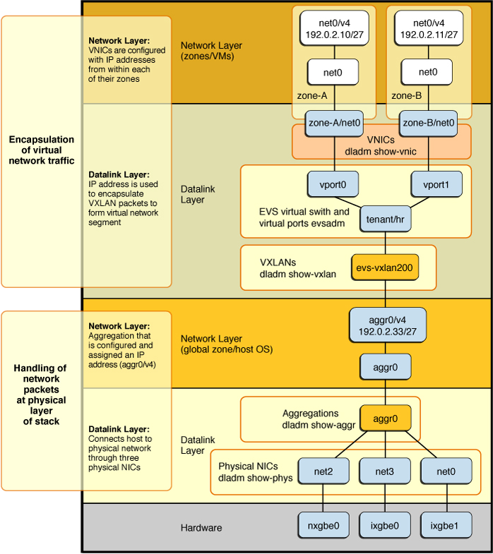
The following figure shows how you might create a highly available and integrated virtual network stack for cloud environments by using aggregations, VNICs, VXLANs, and an EVS switch.
Figure 3 Combining Aggregations With VXLANs, VNICs, and an EVS Switch

The scenario as illustrated uses VXLANs, which provide virtual network segments that are encapsulated within IP packets. Consequently, the datalink and network layers therefore twice in the stack: one to show the handling of packets at the physical layer and the second to show the encapsulated virtual network traffic within these layers of the stack.
The figure shows the following configuration details:
-
On the hardware layer, multiple physical NICs (net0, net2, and net3) are aggregated to create aggr0.
-
The aggregation is configured with an IP address, aggr0/v4 (192.0.2.33/27).
-
An EVS virtual switch tenant/hr is created on top of the IP interface aggr0. In this figure, EVS is configured to use a VXLAN.
The new vxlan0 datalink is connected to a virtual L2 network that overlays the IP network.
-
Assuming that EVS assigned the virtual switch a VXLAN ID of 200, EVS automatically creates a VXLAN datalink called evs-vxlan200, which is associated with the tenant/hr virtual switch.
-
The EVS switch has two virtual ports (vport0 and vport1), which are connected to two VNICs that are used by two zones. The VNICs appear in the zone as datalinks named net0 and are visible from the global zone as zone-A/net0 and zone-B/net0.
-
Managing Network Virtualization and Network Resources in Oracle Solaris 11.4
For reference, refer to the following resources: