This section provides instructions for each phase of the initial power-on sequence.
Before powering on the system or installing any server equipment into the rack, read the Important Safety Information for Oracle's Hardware Systems (7063567) document included with the system.
Before powering on the system, review the following safety precautions. Failure to observe these precautions can result in personal injury, equipment damage, or malfunction.
Do not block ventilation openings.
Do not place cables under the equipment or stretch the cables too tightly.
Do not disconnect power cords from the equipment while its power is on.
If you cannot reach the connector lock when disconnecting LAN cables, then press the connector lock with a flathead screwdriver to disconnect the cable. You could damage the system board if you force your fingers into the gap rather than using a flathead screwdriver.
Do not place anything on top of the system or perform any work directly above it.
Do not let the room temperature rise sharply, especially during winter. Sudden temperature changes can cause condensation to form inside the system. Allow for a sufficient warm-up period prior to system operation.
Avoid static electricity at the installation location. Static electricity transferred to the system can cause malfunctions. Static electricity is often generated on carpets.
Confirm that the supply voltage and frequency match the electrical ratings indicated on Oracle Virtual Compute Appliance X3-2.
Do not insert anything into any system opening, unless doing so is part of a documented procedure. The system contains high-voltage parts. If a metal object or other electrically-conductive object enters an opening in the system, then it could cause a short circuit. This could result in personal injury, fire, electric shock, and equipment damage.
The following procedure describes how to visually inspect Oracle Virtual Compute Appliance X3-2 after it is in place at your site, and prior to power being applied to the system.
Check for rack damage.
Check the rack for loose or missing screws.
Check your Oracle Virtual Compute Appliance X3-2 for the ordered configuration. Refer to the Customer Information Sheet (CIS) on the side of the packaging.
NoteOracle Virtual Compute Appliance X3-2 is preconfigured by Oracle as a self-contained system. You should not move any equipment or add any unsupported hardware to the system.
Check that all cable connections are secure and firmly in place as follows:
Check the power cables. Ensure that the correct connectors have been supplied for the data center facility power source.
Check the network data cables.
Check the site location tile arrangement for cable access and airflow.
Check the data center airflow that leads in to the front of the system.
For more information, see Section 2.5, “Ventilation and Cooling Requirements”.
The following procedure describes how to connect power cords to Oracle Virtual Compute Appliance X3-2.
Open the rear cabinet door.
Ensure that the correct power connectors have been supplied.
Unfasten the power cord cable ties.
The ties are for shipping only and are no longer needed.
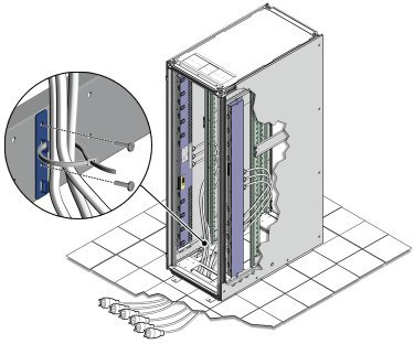
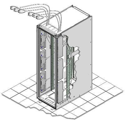
Route the power cords to the facility receptacles either above the rack or below the flooring. See Figure 5.1 and Figure 5.2.
Secure the power cords in bundles. See Figure 5.1.
Plug the power distribution unit (PDU) power cord connectors into the facility receptacles.
The following procedure describes how to power on Oracle Virtual Compute Appliance X3-2.
You can connect to Oracle Virtual Compute Appliance X3-2 using a network connection to monitor the system power-on procedure. For instructions, see Section 5.3.5, “Connect Oracle Virtual Compute Appliance X3-2 to the Network”.
Ensure that the three main power cords are connected to a reliable power source.
For more information, see Section 2.3, “Electrical Power Requirements”.
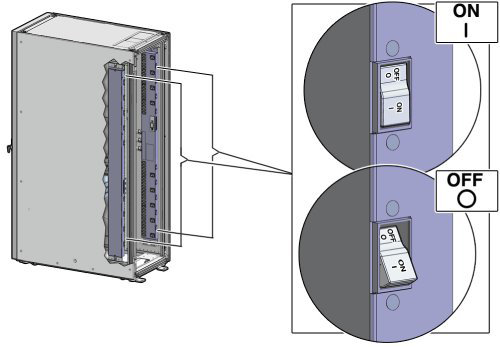
Switch on the power distribution unit (PDU) circuit breakers located on the rear of PDU A and B inside Oracle Virtual Compute Appliance X3-2.
The circuit breakers are on the rear of the system cabinet as shown in Figure 5.3. Press the ON (|) side of the toggle switch.
NoteEnsure that the PDU switches have had power applied for approximately two minutes to complete power-on configuration before starting the management nodes.
Make sure that the circuit breakers located on the rear left and right side power supplies of the Sun ZFS Storage Appliance are in the ON (|) position.
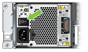
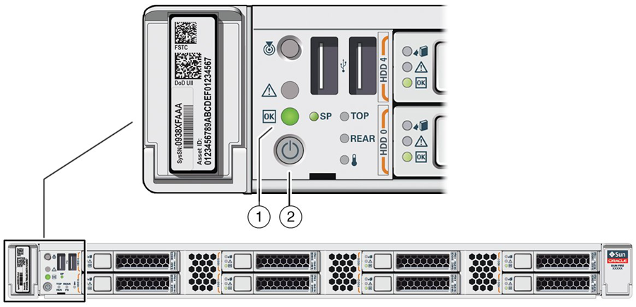
Press the Power button located on the front of the first (bottom) Sun Server X3-2 management node. See Figure 5.5.
The first management node is located in rack unit 5 (U5). The second management node is located in rack unit 6 (U6). It is switched on and configured automatically during the initial power-on sequence.
A management nodes take approximately three to five minutes to power on completely. Once complete, the Power/OK LED illuminates and remains a steady green.
After powering on the first management node, wait while the second management node and all compute nodes are powered on and discovered.
NoteAfter power is applied, the LEDs on all compute nodes and storage server heads will start to blink after approximately two minutes. From the rear of the rack, you can see the green LEDs on the power supply units (PSUs) on the Sun Server X3-2 compute nodes turn on instantly after power is applied. In addition, from the rear of the rack, you can see the display on the power distribution units (PDUs) illuminate once power is available.
The management nodes will verify all components within the system. The management nodes ensure that the correct networking switches and storage devices are installed in the system, and search for compute nodes to add to the compute fabric. Once compute nodes are located, the management nodes automatically install the proper drivers and the Oracle VM Server version 3.2.5 operating system on each compute node.
Depending on your system configuration, the Oracle Virtual Compute Appliance X3-2 power-on process should take approximately three to five minutes to become available for use, and 20 to 30 minutes for the entire fabric to be ready. When completed, message alerts will appear in the web browser configuration utility alerting you to configure initial system settings (for example: network properties and passwords). For instructions on connecting to the Oracle Virtual Compute Appliance X3-2 and accessing the web browser configurator utility, see Section 5.3.5, “Connect Oracle Virtual Compute Appliance X3-2 to the Network”.
For initial access to Oracle Virtual Compute Appliance X3-2, you can use the pre-installed blue Ethernet cable connected to port 24 on the Oracle ES1-24 switch to connect a workstation with a monitor. The Oracle Virtual Compute Appliance Dashboard can be reached by means of a web browser.
Port 24 of the Oracle Switch ES1-24 has a minimum transfer rate of 1000 Mbit/s (GbE). If your workstation requires a lower speed (Fast Ethernet, 100 Mbit/s), you may use port 19 of the second Oracle Switch ES1-24, which is the one on the right hand side if you look from the rear of the rack. A Cat5 Ethernet cable is plugged in and coiled up on the side.
You can connect to the Ethernet port at any time during the system power-on process. However, you should wait approximately two to three minutes after starting the power-on process to allow the IP address to become active. If you connect too soon to the port, you will see an HTTP error code 404 or similar code. If this occurs, wait a few minutes and try to connect again.
You can connect Oracle Virtual Compute Appliance X3-2 to the network as follows:
Ensure that the F1-15 Director switch is connected to your data center (public) network.
For details, see Section 3.1.1, “Network Connection Requirements”.
Connect a workstation with a web browser directly to the management network using the supplied blue Ethernet cable connected to port 24 of an Oracle ES1-24 switch.
CautionPort 24 of the Oracle Switch ES1-24 has a minimum transfer rate of 1000 Mbit/s (GbE). If your workstation requires a lower speed (Fast Ethernet, 100 Mbit/s), you may use port 19 of the second Oracle Switch ES1-24, which is the one on the right hand side if you look from the rear of the rack. A Cat5 Ethernet cable is plugged in and coiled up on the side.
Configure the wired network connection of the workstation to use the static IP address 192.168.4.254.
Using the web browser on the workstation, connect to the Oracle Virtual Compute Appliance Dashboard with the predefined IP address of the first management node: https://192.168.4.3:7002/ovca.
192.168.4.3 is the predefined port IP address for configuring Oracle Virtual Compute Appliance X3-2. If there is another device on your network that is using this IP address, you should change the conflicting device's IP address prior to connecting to Oracle Virtual Compute Appliance X3-2.
Log into the Dashboard using the user name ovcaadmin and password Welcome1.
The Dashboard opens in the Hardware View tab. This view indicates the status of the appliance as it is being powered on. All the networking and storage should be green. As the compute nodes are discovered, they will change from red to green. Once the system has discovered and provisioned at least one compute node, the Dashboard interface becomes available.
Using the Dashboard, configure the system environment parameters, including: domain name, NTP and DNS servers.
Go to the Network Setup tab and replace the default IP configuration of the management nodes with the reserved IP addresses in your data center network. Enter the default gateway of your data center network.
NoteDuring the initial configuration of the Oracle Virtual Compute Appliance X3-2, you change the predefined configuration IP address to the reserved virtual IP address in your data center network. For details, see Section 3.1.2, “IP Address Requirements”.
Reconnect to the Oracle Virtual Compute Appliance Dashboard at the new virtual IP address of the management node cluster: https://
<virtual_ip>:7002/ovca.
For details about the software configuration process, and for advanced configuration and update options, refer to the Oracle Virtual Compute Appliance X3-2 Administrator's Guide.