1 Introduction
Oracle's StorageTek T10000 tape drive family provides a range of small, modular, high-performance units designed for high-capacity data storage. The tape drive is either rack mounted or used in various StorageTek libraries (Figure 1-1). There are four models in the T10000 drive family: T10000A, T10000B, T10000C, and T10000D.

Illustration Legend:
1 - SL8500 configuration
2 - SL3000 configuration
3 - L180/L700e/L1400M configuration (T10000A and T10000B only)
4 - Rack mount configuration
The following libraries support certain models of the T10000 tape drive family:
-
SL3000
-
SL8500
-
L180/L700e/L1400M (T10000A and T10000B only)
-
9310 (T10000A only)
Tape Drive Description
The drive uses a unique, single-reel cartridge. The file reel is located inside the cartridge while the machine reel resides inside the tape drive. The drive uses a technology called partial response, maximum likelihood (PRML) to provide a high-density data format. PRML enables recording and storing an uncompressed capacity of up to:
-
StorageTek T10000 cartridge:
-
500 gigabytes (GB) with the T10000A tape drive
-
1 terabyte (TB) with the T10000B tape drive
-
-
StorageTek T10000 T2 cartridge:
-
5.5 terabytes (TB) with the T10000C tape drive
-
8.5 terabytes (TB) with the T10000D tape drive
-
The T10000A drive can read and reclaim a tape cartridge written by a T10000A drive.
The T10000B drive can:
-
Read and reclaim a tape cartridge written by a T10000A drive.
-
Write, read, and reclaim a tape cartridge written by a T10000B drive.
The T10000C drive can:
-
Read tape cartridges written by either a T10000A or T10000B drive.
-
Write, read, and reclaim a tape cartridge written by a T10000C drive.
The T10000D drive can:
-
Read tape cartridges written by a T10000A, T10000B, or T10000C drive.
-
Reclaim tape cartridges written by a T10000C drive.
-
Write, read, and reclaim a tape cartridge written by a T10000D drive.
The tape drive uses fiber optic host connections to provide a high data-transfer rate.
Note:
See Appendix E, "Specifications" and Appendix F, "Controlling Contaminants" for additional specifications and requirements.Library Tray Rear Panel
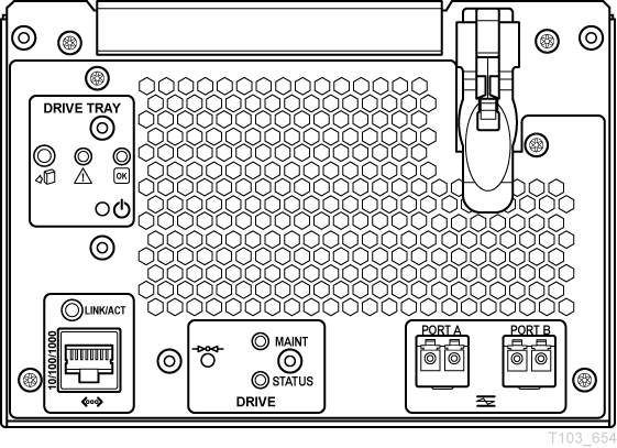
The library tray rear panel has specific tape drive items (see Figure 1-2 for an example of a rear panel):
-
Interface ports
-
Ethernet port
-
Tape drive indicators
The T10000A/B/C indicators are labeled STATUS and CRYPT.
The T10000D indicators are labeled STATUS and MAINT.
-
Tape drive maintenance push button
Interface Ports Use
It is not recommended to connect a T10000 tape drive to the same host bus port with another tape or a disk subsystem. The stress on the host bus adapter, due to the bandwidth needs, creates unacceptable error recovery issues between both solutions.
The T10000 tape drive supports connection of both ports, in accordance with ANSI Fibre Channel specifications (refer to InterNational Committee on Information Technology Standards [INCITS] documents: SCSI Primary Commands -3, Section 5.6, and Fibre Channel Protocol -3). The drive will support two hosts if they each honor the Reserve/Release or the Persistent Reserve/Release specifications.
Maintenance Port Use
All service calls for tape drives under warranty, maintenance contract, or time-and- materials service require physical access and connection to the rear panel maintenance (Ethernet) port.
If a customer has an Ethernet cable physically connected to the drive requiring service, the service person must disconnect this cable to perform the required service action.
-
T10000 non-encryption drives supported by the remote support platform require 100% dedication of the drive's Ethernet port to the platform.
-
T10000 encryption-enabled drives require 100% dedication of the drive's Ethernet port to the Encryption Service Network except during service activities performed by authorized personnel.
Where Encryption and the remote support platform coexist, the Ethernet Port must be concurrently shared by using the Service Network.
Note:
Oracle neither supports nor assumes any responsibility for drive functional failures that occur during the unauthorized use of the drive's maintenance port.Unauthorized use applies to any use of the drive's Ethernet port for other than the following items:
-
Encryption 1.x environments (not supported by T10000C and T10000D)
-
Encryption 2.x and 3.x environments
-
StorageTek Virtual Operator Panel (VOP) customer or service versions
-
Service Delivery Platform (SDP)
-
Service's Tape Health Check Tool
-
StorageTek Diagnostic System (STDS)
The T10000C and T10000D drives support IPv6 addressing. With drive code level 1.40.x07 or higher, the T10000A orB drive supports IPv6 addressing.
SL3000 Library Tray (New Design)
The rear panel of an SL3000 library drive tray, new design (T10000D version), is shown in Figure 1-3.
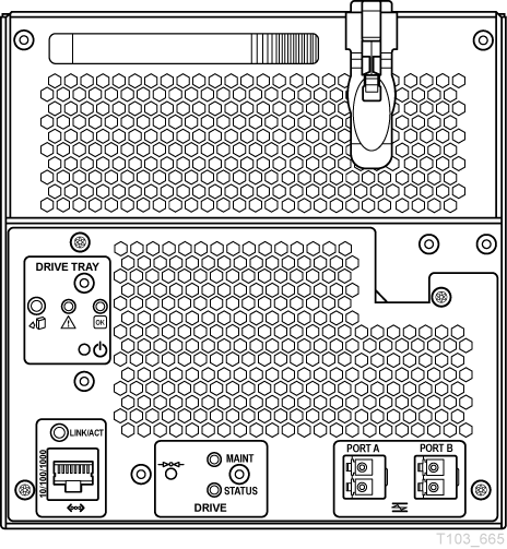
Status and Maintenance Indicators
The T10000D drive tray has two single color indicators: STATUS (green) and MAINT (yellow). Older model T10000 drives have STATUS and CRYPT indicators.
The state of the indicator(s) conveys a meaning:
- Green indicator only (on solid)
-
Indicates the drive is functional.
- Green indicator only slow flashing
-
The drive is in boot monitor mode.
- Green indicator only fast flashing
-
The drive is in IPL mode.
- Yellow indicator only (on solid)
-
The drive is in maintenance mode.
- Yellow indicator only fast flashing
-
The drive is in dump mode.
- Green indicator and Yellow indicator on solid
-
The drive requires service.
- Green and Yellow indicators alternating for one cycle
-
Drive is resetting.
- Green and Yellow indicators alternating for one minute
-
Visual indication to identify the drive for a specific purpose.
- Green and Yellow indicators off
-
The drive is powered down.
T10000 A, B, or C Library Tray (Original Tray Design)
The rear panel has a push-button switch, two multi-color indicators, and three connectors. The drive status indicator is on all drives while the encryption status indicator is only on encryption-capable T10000A, B, or C drives. The tape drive specific items are grouped together on the bottom edge of the rear panel with the MAINT push-button on the left and the Ethernet connector on the right (see Figure 1-4).
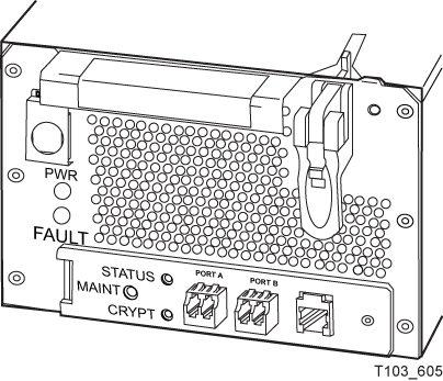
Note:
See Table 1-1 for drive status indicator states. See "Encryption Status Indicator" for encryption status indicator states.Drive Status Indicator
The drive status indicator on the rear panel indicates the general status of the drive. The normal sequence of the drive status indicator during the drive power-on IPL: slow-flashing red, slow-flashing amber, steady or slow-flashing green.
Note:
The slow flash rate is one cycle per second, and the fast flash rate is two cycles per second. Some indications alternate between two colors at the slow flash rate.Table 1-1 interprets the various states of the drive status indicator:
Table 1-1 Drive Status Indicator State Descriptions
| Indicator State | Description | Meaning/Action |
|---|---|---|
|
Off |
Drive powered off |
Power not applied to the drive. Turn on the power supply. Possible power related failure if it remains off with power supply switch on. |
|
Red |
Hardware failure |
Processor not functioning. Call for service. |
|
Red (slow flash rate) |
IPL started |
Booting, no communication with the drive until the IPL completes. |
|
Amber (slow flash rate) |
Functional code loading |
Initializing, no communication with the drive until the IPL completes. |
|
Green |
IPL complete (dumps not present) |
Normal operating condition, drive is ready for functional tasks. Communication with drive is possible. |
|
Green (slow flash rate) |
IPL complete (dumps are present) |
Normal operating condition, drive is ready for functional tasks. Communication with drive is possible. |
|
Amber |
Boot Monitor |
Engineering maintenance mode. Call for service. |
|
Red and Blue (alternating) |
Hardware failure |
Power on failure. Call for service. |
|
Red and Green (alternating) |
Service mode |
Initiated by service representative. While in the service mode, the drive's IP is static 10.0.0.1. |
|
Red and Green (alternating) |
Dump-again state |
If indication is present without service mode active, it could indicate a recurring malfunction is present. Call for service. |
|
Red (fast flash rate) |
Dump in progress |
Do not remove power while the drive is performing a dump operation (drive memory could be corrupted). There is no communication. |
|
Amber (fast flash rate) |
Firmware update in progress |
Do not disturb the drive until the firmware update is complete. When the update is complete, the indicator will change to green fast flashing. |
|
Green (fast flash rate) |
Firmware update is complete |
Initiate an IPL when the drive is idle, if the IPL did not auto-initiate. |
Encryption Status Indicator
T10000A, B, or C drives that are encryption capable have a multi-color encryption status indicator on the rear panel of the tape drive.
If the encryption status indicator is green, it indicates that the drive is encryption capable, but not encryption enabled. In this state, the drive functions only in a non-encryption Safe mode and can neither read nor write encrypted tape cartridges. However, the drive can function normally for non-encryption tasks.
After the drive is encryption enabled, the indicator turns red to show that the drive is Armed and functional in the encryption mode. In this state, the drive can read and write encrypted tape cartridges. The drive can also read non-encrypted tape cartridges, but cannot write to non-encrypted tape cartridges.
The states of the encryption status indicator are:
Note:
Slow flash rate is 1 cycle per second.Indicator state: Off
-
The drive does not have encryption hardware.
Indicator state: Green
-
Encryption capable, but not enabled.
-
KMS 1.X: Not encrypting
-
KMS 2.x or OKM: Not licensed
-
-
Normal, unencrypted drive write and read cartridge operations.
Indicator state: Green (slow flashing)
-
Mode: Reset
-
Encryption previously enabled, but requires keys. The drive performs read-only, unencrypted cartridge operations.
Note:
The drive cannot perform an unencrypted write operation after encryption has been enabled.
Indicator state: Red
-
Mode: Armed, idle
-
Encryption enabled or active. Ready to encrypt.
Indicator state: Red (slow flashing)
-
Mode: Armed, active
-
Encryption read or write cartridge operation in progress.
Indicator state: Amber
-
KMS 1.X: Requires media key.
-
KMS 2.x or OKM:
-
Enrolled, cartridge not loaded.
-
Enrolled, cartridge loaded but waiting for KMS key.
-
Indicator state: Amber (slow flashing)
-
Requires device key (KMS 1.x only).
Indicator state: Cycling
Note:
The indicator continuously cycles through several colors at the slow flash rate.-
Mode: Zeroed
Media, device, and enabling keys missing. The drive is unusable, and it must be returned to manufacturing.
Refer to Crypto Key Management documentation for additional information:
Encryption Options
Encryption-capable T10000 tape drives support data-at-rest encryption.
Federal Information Processing Standards compliance:
-
FIPS PUB 140-2, Security Requirements for Cryptographic Modules
-
Level 1: The basic level with production-grade requirements.
-
Level 2: Adds requirements for physical tamper evidence and role-based authentication.
-
-
The T10000A drive with code level 1.40.x07 and Key Management System (KMS) 2.1, complies with FIPS Level 1.
-
The T10000B drive with code level 1.40.x07 and Key Management System (KMS) 2.1, complies with FIPS Level 2.
-
The T10000C drive with code level 1.51.318 and the Oracle Key Manager provides FIPS 140-2 Level 1 security to data on magnetic tape.
-
The T10000D drive with code level 4.07.107 and the Oracle Key Manager provides FIPS 140-2 Level 1 security to data on magnetic tape.
There are four encryption modes:
-
Encryption off (manufacturing default).
-
Encryption enabled (on/off switchable) with keys obtained from a KMS.
-
Encryption permanently enabled with keys obtained from a KMS (protected with AES Key wrap). In this mode, encryption cannot be turned off.
-
DPKM (see "Data Path Key Management").
Key Management Solutions
The StorageTek Crypto Key Management Station (KMS 1.x), StorageTek Crypto Key Management System (KMS 2.x), and Oracle Key Management (OKM 3.x) provide device-based encryption solutions. The tape drive is shipped from the factory encryption-capable, but not encryption-enabled. You must explicitly enable the drive for encryption.
Note:
A drive that has not been enabled for encryption can neither read nor append to any encrypted tape cartridge. It can, however, overwrite an encrypted tape from the beginning of tape (BOT).What an Encryption-Enabled T10000 Tape Drive can do:
-
Write to a tape cartridge in encrypted mode only, using its assigned write key
-
Read an encrypted tape cartridge, if it has the proper read key
-
Read non-encrypted tape cartridges—can neither write to nor append to the cartridge
-
Format or reclaim tape cartridges
What an Encryption-Enabled T10000 Tape Drive cannot do:
-
Append non-encrypted data to an encrypted tape cartridge
-
Write a non-encrypted tape cartridge
Oracle/StorageTek Encryption Resources
For additional information on the encryption capabilities and features of the T10000 Tape Drive, see the Oracle Key Manager documentation link at:
https://docs.oracle.com/en/storage#sw
For further information on the encryption option, see your sales representative.
Data Path Key Management
The data path key management (DPKM) subsystem is the third installment of encryption for StorageTek tape drives. DPKM uses the SCSI 4 commands Security Protocol In and Security Protocol Out to implement host-based key management on StorageTek encrypting tape drives. Encryption keys are delivered to the tape drive over the Fibre Channel interface (non-FIPS compliant). DPKM provides the ability to toggle the encryption state on/off on a per cartridge basis which enables the user to have a mix of encrypted/non-encrypted files on each tape cartridge. You use the Virtual Operator Panel to enable or disable the DPKM capability of the tape drive.
Dumps will not be encrypted if the drive setting is either Encryption off or DPKM.
Normal drive firmware updates are not allowed in DPKM mode. When the drive is in DPKM mode, follow these instructions to update firmware:
-
The crypto officer (CO) is required to turn off DPKM.
Note:
Turning off DPKM requires a reboot and the drive IPLs into the Encryption off mode. -
The CO updates the firmware.
The drive may or may not reboot automatically after the firmware is updated.
If the drive does reboot, it IPLs in the Encryption off mode.
-
The CO can enable DPKM which causes the drive to reboot and IPL into DPKM mode.
Interface with the Tape Drive
The T10000 tape drive does not have a built-in physical operator panel; therefore, your communication with library-attached drives is normally through the Virtual Operator Panel (VOP) application.
Virtual Operator Panel
The VOP application window (Figure 1-5) provides a graphical user interface (GUI) to the connected drive. The GUI has a menu bar, a section that provides several drive status indicators and two drive message windows (primary and secondary), and the bottom portion of the GUI contains the VOP text message pane. Additional information is available in the Virtual Operator's Panel User's Guide.
Note:
When you use VOP with a T10000C drive, another indicator is present that shows the drive hibernate status.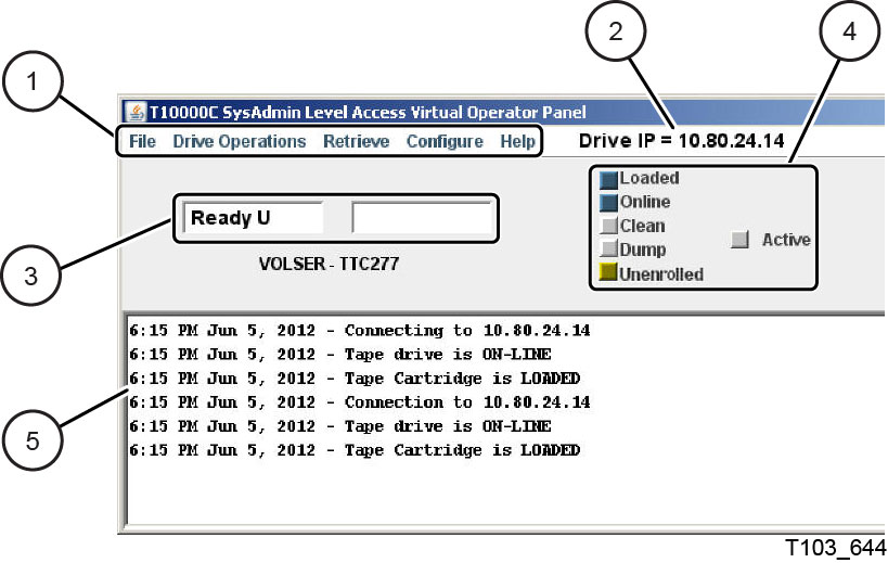
Illustration Legend:
1 - Menu bar
2 - Drive IP or name
3 - Primary and secondary drive message windows
4 - Drive status indicator
5 - VOP text message area
Download VOP from the following URL: http://edelivery.oracle.com/
Library Drives
Manual drive operations, such as configuration settings and utilities, can be directed by VOP through the drive's rear panel Ethernet maintenance port.
Rack Mount Drives
Rack mounted drive operation is normally accomplished through the drive tray chassis operator panel (see "Operator Panel Controls and Indicators"). However, you can also operate it with VOP and a connection to the Ethernet port on the rear panel of the drive tray chassis.
Secure Configuration
The VOP is designed to operate on a service network configured as a private LAN. VOP, tape drives, the Crypto Key Management Station (if drives are encrypted), and Ethernet switches are potential components of the private LAN. The private LAN best practice recommendation ensures security from unauthorized access. See the StorageTek Crypto Key Management System, Systems Assurance Guide for details regarding the service network private LAN.
StorageTek Library Console
The SL3000 and SL8500 libraries have a GUI called the StorageTek Library Console (SLC) that presents basic drive information. The system detail drive folder, shown in the following figure, contains a list of installed drives and data about each drive (such as the drive access state, the drive type, the drive serial number, and the version of drive code).
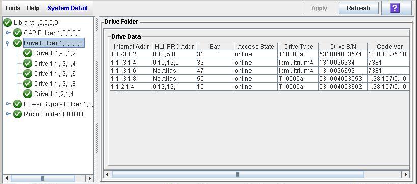
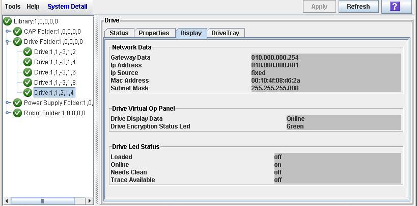
When you select a specific drive, additional unique data is available for that drive such as the drive status, drive properties, drive display, and drive tray information (see Figure 1-7).
Note:
The SLC drive folder information changes frequently, and the actual data displayed might differ from the example. Click the question mark button on the GUI for additional information.T10000 Cartridges
The T10000 tape drives support five types of cartridges:
-
StorageTek T10000 cartridge (T10000A or B drive):
-
Data: 500 gigabytes T10000A or 1 terabyte T10000B
-
Data, sport: 120 gigabytes T10000A or 240 gigabytes T10000B
-
VolSafe, capacity: 500 gigabytes T10000A or 1 terabyte T10000B
-
VolSafe, sport: 120 gigabytes T10000A or 240 gigabytes T10000B
-
Cleaning cartridge: 50 uses (CT or CL cartridge)
-
-
StorageTek T10000 T2 cartridge (T10000C or D tape drive):
-
Data: up to 5.5 terabytes T10000C or 8.5 terabytes T10000D
-
Data, sport: 1 terabyte T10000C or 1.6 terabytes T10000D
-
VolSafe, capacity: up to 5.5 terabytes T10000C or 8.5 terabytes T10000D
-
VolSafe, sport: 1 terabyte T10000C or 1.6 terabytes T10000D
-
Cleaning cartridge: 50 uses (CC or CL cartridge)
Note:
The T10000 tape drives do not accept a data cartridge for any other type of tape drive.
-
Figure 1-8 identifies key areas of the StorageTek T10000 tape cartridge.
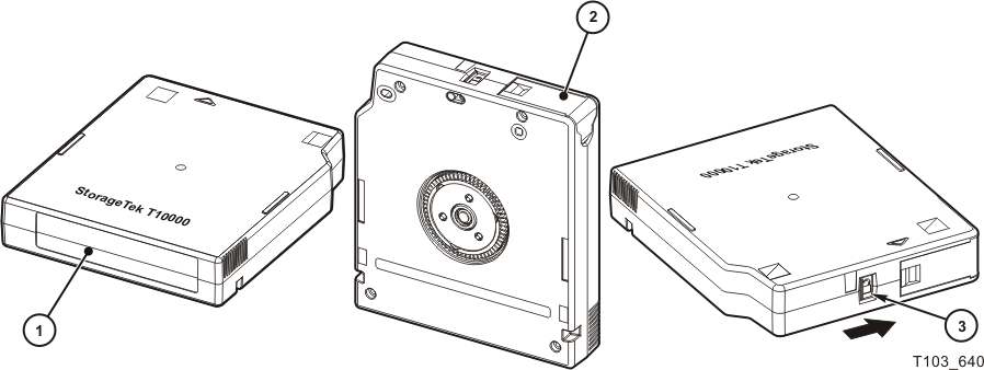
Illustration Legend:
1 - Volume label
2 - Leader access door (black, red, yellow, or white depending on cartridge type)
3 - Finger grips
4 - File protect switch (black, red, yellow, or white depending on cartridge type)
5 - Hub
Standard Data Cartridge
Data cartridges are the standard common read and write data cartridges (also referred to as native). The data cartridge has a black leader access door (see Figure 1-8). Labeled cartridges have a media identifier of either T1 (StorageTek T10000) or T2 (StorageTek T10000 T2).
The StorageTek T10000 data cartridge specification supports 15,000 mounts.
The StorageTek T10000 T2 data cartridge specification supports 25,000 mounts.
Note:
The tape drive issues a warning message to the host when that number is exceeded.A mount is defined as the tape drive threading the tape onto the take-up reel and moving to the load point.
Diagnostic Cartridges
The Diagnostic cartridge is a special-use version of the data cartridge with a special label. The diagnostic cartridge is typically used by a service representative and most libraries store one or more diagnostic cartridges (see "Diagnostic Cartridge Labels").
Sport Cartridges
The Sport cartridge is a lower capacity version of the native data cartridge. The Sport cartridge has a red leader access door (see Figure 1-8).
The StorageTek T10000 cartridge specification supports 15,000 mounts.
The StorageTek T10000 T2 cartridge specification supports 25,000 mounts. The tape drive issues a warning message when that number is exceeded.
VolSafe Data Cartridges
VolSafe data cartridges are write-once data cartridges. They cannot be erased without destroying the tape itself. The tape drive writes data on the tape and appends data to the cartridge on free space until the cartridge is full. The tape drives may read the cartridge multiple times. VolSafe cartridges are commonly used for information that must be stored for legal reasons and not altered. There are two versions of the VolSafe cartridge:
-
VolSafe cartridge—you can identify this cartridge by a yellow leader access door (see Figure 1-8). This cartridge has the same capacity as the standard data cartridge.
-
Sport VolSafe cartridge—you can identify this cartridge by a yellow leader access door and red file protect switch (see Figure 1-8). This cartridge has the same capacity as the sport data cartridge.
Cleaning Cartridges
As the name implies, you would use a cleaning cartridge to clean a drive head up to 50 times. An attempt to use a cleaning cartridge beyond that number results in the tape drive rejecting the cleaning cartridge and posting an error message to the host. You can identify a cleaning cartridge by a white leader access door (see Figure 1-8). There are several versions of the cleaning cartridge:
-
T10000A or B cleaning cartridge (CT media identifier)
-
Cleaning cartridge for the T10000C only (CC media identifier)
-
Cleaning cartridge which cleans all four T10000 drive models (CL media identifier)
Media Information Region
The T10000 tape drives use information recorded on each tape cartridge to reduce access times and manage the useful life of the cartridge. This information is recorded in the cartridge's radio frequency identification (RFID) chip and at the beginning of tape in an area known as the media information region (MIR). The information stored in the RFID is a proper subset of the information stored in the MIR. The media information falls into two categories: statistical counters and data pointers.
Statistical Counters
Statistical counters reflect use of the cartridge and includes read and write activity, error activity, cumulative mounts, and other information about its use.
Data pointers
The data pointer information is a directory (map) used to locate the customer (logical) data on the physical tape media. Because customer data is compressed and written in drive controlled blocks on the tape, a map is needed to efficiently locate the data after it is written. This map provides an index between customer data and the physical block on the tape media. After data is written, the drive accesses this map to optimize access to the customer data.
To locate or space to customer data, the logical object that identifies the block is translated to the physical location on the tape media, and the drive determines the quickest method to read the block. If the block is some physical distance from the current location, a calculation results in a high-speed locate to the block location and is followed by a normal speed read.
The existence of the media information is usually transparent to the customer unless it has a problem. This can occur if the information update fails during a dismount. The impact of invalid media information occurs in several areas. Because it enables high speed positioning, invalid media information forces all operations to a slow speed mode. This has no impact on a sequential read from the beginning of the tape. However, any operation using locate defaults to a sequential slow-speed read to the requested block, which can result in longer processing time.
Note:
Invalid media information might be suspected if you observe poor performance on a specific tape cartridge.The following sections describe how media information is processed and some potential implications of problems with the information.
Normal Processing
Every time a tape cartridge is loaded, the media information is read from the tape media and saved in drive-resident memory. After being loaded in drive memory, a read-invalid state is written in the tape-resident RFID. The tape-resident media information is marked open, read-invalid because it does not reflect results of activity in the current mount session. All subsequent media information accesses during the current mount session are saved in the drive-resident information. If no writes are performed to the cartridge, the RFID remains in the read-invalid state meaning the MIR directory information is still completely valid. After a write takes place, the RFID is marked write-invalid meaning the MIR directory information on tape is invalid.
The T10000 drives use the drive-resident copy of the information to access customer data pointers for read-only functions. Statistical counters are continuously updated in the memory-resident information with any drive activity.
When the cartridge is unloaded as part of the unload routine, the drive-resident information is written to the cartridge's RFID and the tape-resident MIR with the closed state indication set.
Cross-Density Cartridge Processing
Whenever a data cartridge is loaded that was written in a data density format that is different from the one used when the drive writes, model-specific MIR processing occurs. In an environment with mixed T10000 drive models, a mandatory firmware update provides the capability for the lower-density drive to read the RFID of a higher-density drive.
For a native data cartridge or Sport cartridge written by a T10000A drive, the:
-
RFID can be read or updated by a T10000A, B, C, or D drive.
-
MIR can be read by a T10000A, B, C, or D drive.
-
MIR cannot be updated by a T10000B, C, or D drive.
-
T10000A, B, C, or D drive counters can be updated after appropriate firmware updates are installed.
-
Cartridge can be reclaimed by a T10000A or B drive.
For a native data cartridge or Sport cartridge written by a T10000B drive, the:
-
RFID can be:
-
Read by a T10000A, B, C, or D drive.
-
Updated by a T10000B, C, or D drive.
-
-
MIR can be read by a T10000B, C, or D drive.
-
MIR cannot be updated by a T10000A, C, or D drive.
-
T10000B, C, or D drive counters can be updated after appropriate firmware updates are installed.
-
Cartridge can be reclaimed by a T10000A or B drive.
Note:
When the T10000A or B drive identifies the data cartridge as an unreadable-density data format, it displays 3215 on the Virtual Operator Panel (VOP) or the physical operator panel of the rack mount drive.
For a native data cartridge or Sport cartridge written by a T10000C drive, the:
-
RFID can be:
-
Read by a T10000A, B, C, or D drive.
-
Updated by a T10000C or D drive.
-
-
MIR can be read by a T10000C or D drive.
-
MIR cannot be updated by a T10000A or B drive.
-
T10000C drive counters can be updated after appropriate firmware updates are installed.
-
Cartridge can be reclaimed by a T10000C or D drive.
For a native data cartridge or Sport cartridge written by a T10000D drive, the:
-
RFID can be:
-
Read by a T10000A, B, C, or D drive.
-
Updated by a T10000D drive.
-
-
MIR can be read by a T10000D drive.
-
MIR cannot be updated by a T10000A, B, or C drive.
-
T10000D drive counters can be updated after appropriate firmware updates are installed.
-
Cartridge can be reclaimed by a T10000D drive.
Invalid Media Information Conditions
There are four media invalid conditions for the T10000 drives:
-
Cartridge's RFID is unreadable. The drive refuses to mount the cartridge (FSC of 403B). Return the cartridge to engineering to recover the customer data.
-
Cartridge's RFID can be partially read. The drive mounts the cartridge as read-only.
-
RFID and MIR are out-of-sync. None of the block information, coarse-grained in the RFID or fine-grained in the MIR, can be trusted. The cartridge is usable but the drive must rebuild the block information as it sequentially reads all of the data up to the desired customer data.
Note:
This scenario can cause the drive to spend an hour or more rebuilding the block information, potentially causing the application running on the host to time out. -
MIR is corrupted or unreadable. The fine-grained block location information on the cartridge cannot be used; the tape can be used with the coarse-grained block information on the RFID but with lower performance.
The drive posts a 4031 or 4032 informational FSC whenever it loads a cartridge with an invalid MIR. When a tape cartridge has an invalid media information, some action is required to correct it. Invalid media information can be corrected in several ways:
-
Run the media correction utility through the VOP (see "To Rebuild the MIR (VOP)").
-
The drive recovers the media information as it processes host commands, but very slowly.
-
Tape Drive Features
The following features are available for the T10000C and T10000D tape drives.
Some of the feature descriptions refer to white papers which are located at:
http://www.oracle.com/technetwork/server-storage/sun-tape-storage/documentation/index.html
StorageTek Data Integrity Validation
StorageTek Data Integrity Validation (DIV) ensures that a checksum, provided by an application or file system, is validated by the StorageTek T10000 for each record sent to the drive. The user-generated checksum is stored with each record on tape and can be checked on any future read or verify operation (without the added overhead of sending data to the host). Information about how to use this feature is available in:
-
StorageTek T10000 Tape Drive Fibre Channel Reference Manual
-
Redefining Tape Usage with StorageTek Tape Tiering Accelerator and StorageTek In-Drive Reclaim Accelerator (white paper)
The DIV feature is available for the FC tape drive and requires application support.
StorageTek Maximum Capacity
Maximum Capacity enables the use of tape capacity that is normally reserved to ensure tape-to-tape copy operations succeed. The StorageTek T10000 Tape Drive Fibre Channel Interface Reference Manual describes how to use this feature. This feature increases the capacity of the T10000C to as much as 5.5 TB or the T10000D to as much as 8.5 TB.
Maximum capacity is off by default (enabled through VOP), available on FC drives and VSM, and no application support is needed.
StorageTek File Sync Accelerator
The StorageTek File Sync Accelerator (FSA) enables applications to reduce or eliminate back hitches that are normally caused by writing a tape mark or other sync operations.
The FSA feature is on by default (disabled through VOP), available on FC and FICON drives, and no application support is needed.
Refer to the white paper Maximizing Tape Performance with the StorageTek T10000 Tape Drives.
StorageTek Tape Application Accelerator
The StorageTek Tape Application Accelerator (TAA) increases write throughput to tape despite an application inserting sync commands into the data stream. When TAA is enabled, the drive converts tape marks to buffered tape marks and syncs to NO-OPs. Data is written to tape faster because buffered tape marks and NO-OPs do not cause the tape drive to empty the contents of its buffer to tape and back hitch.
The TAA feature is off by default (enabled through VOP), available on FC and FICON drives, and no application support is needed.
Before enabling a TAA configuration, the user must determine how their particular application uses write tape marks and syncs. The terms File Sync and Write Tape Mark are defined differently in FICON and Fibre Channel environments.
-
When TAA is enable in a FICON drive, File Syncs are always converted to NO-OPs and tape marks are always treated as buffered tape marks.
Note:
This feature must only be used in environments that handle deferred errors. When this feature is enabled, sending a tape mark does not ensure the data has successfully been written to the tape. A deferred error may be reported when buffered data is written to tape after the command has completed. In a FICON only environment, duplex write operations should use this feature. -
TAA operation in open systems environments depends on whether the user's storage application automatically restarts a job following a power failure or reset condition.
-
For applications designed to restart a job following a failure event, Oracle highly recommends configuring TAA to convert File Syncs to NO-OPs but without treating tape marks as buffered tape marks.
-
For applications that are not designed to restart a job following a failure event, Oracle highly recommends duplexing output-type jobs to two tape drives.
Refer to the white paper Maximizing Tape Performance with the StorageTek T10000 Tape Drives.
-
StorageTek Search Accelerator
The StorageTek Search Accelerator (SSA) enables FICON applications to search for a string up to 1024 bytes in length. This feature usually enhances Mainframe HSM Audit performance in FICON environments.
The SSA feature is available on FC and FICON drives, and application support is required (an API is available).
Refer to the white paper Using Oracle's StorageTek Search Accelerator.
StorageTek MIR Assisted Search
The StorageTek T10000C and T10000D tape drives support access to the Media Information Region (MIR) of the cartridge. This command is implemented using a SCSI Read Buffer command similar to the StorageTek T10000B tape drive. MIR data provides location information for tape records and can be used by an application to order which records are read first from tape. The T10000 MAS N677 engineering document describes this feature.
The MAS feature is available for the FC tape drive, and application support is required.
StorageTek In-Drive Reclaim Accelerator
The StorageTek In-Drive Reclaim Accelerator (IDR) enables applications to reclaim space on the tape without rewriting the entire tape. The application must save and manage a partition map to get the full benefit of this feature. The StorageTek Virtual Storage Manager (VSM) supports this feature with the StorageTek T10000B, T10000C, and T10000D drives. For more detailed information about this feature, contact your local sales representative to obtain a copy of the ALP User's Guide.
The IDR feature is available on FC and FICON drives, and application support is required (an API is available).
StorageTek Tape Tiering Accelerator
The StorageTek T10000C and T10000D drives have the ability to partition tape. These partitions can be organized by an application to control where file sets are located on tape. Data sets located near the beginning of tape will have faster access characteristics than data written near the end-of-tape (EOT).
-
Applications now have the ability to manage the location of data on the tape.
-
StorageTek Tape Tiering Accelerator (TTA) enables partitions to be read only.
-
TTA provides up to:
-
480 logical volumes on a cartridge written by a T10000C drive
-
600 logical volumes on a cartridge written by a T10000D drive
-
The TTA feature is available on FC and FICON drives, and application support is required (an API is available).
For more detailed information about this feature, contact your local sales representative to obtain a copy of the ALP User's Guide.