2 Rack Mount Controls and Indicators
This chapter provides information about the indicators and switches located on the rack mount drive.
Front Panel
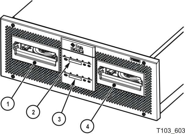
The T10000 Tape Drive rack mount configuration chassis contains one or two drives. The chassis front panel (Figure 2-1) provides manual loading or unloading of tape cartridges into each drive through separate cartridge slots. The front panel also has a dual operator panel mounted between the cartridge slots. The upper portion is for drive A (left), and the lower portion is for drive B (right).
Illustration Legend:
1 - Cartridge slot drive A
2 - Operator panel drive A
3 - Operator panel drive B
4 - Cartridge slot drive B
Load/Unload Slot
The cartridge slots accept only StorageTek T10000 or StorageTek T10000 T2 tape cartridges. All other cartridge types will not load into the T10000 tape drive. After you have inserted a tape cartridge, the loader mechanism lowers the cartridge onto the hub motor, and threads the tape.
Operator Panel Controls and Indicators
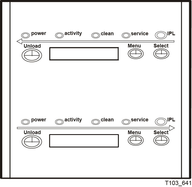
The rack mount chassis dual-operator panel (Figure 2-2) provides independent control and indications for the two rack mount T10000 tape drives. Each section contains four push-button micro-switches, four indicators, and a ten-character display window. Table 2-1 describes the controls, and Table 2-2 describes the indicator indicators.
Table 2-1 is a two column table that lists the four operator panel push button micro-switches and describes their use.
Table 2-1 Operator Panel Controls
| Push Button | Use |
|---|---|
|
Unload |
Initiates a cartridge rewind and unload operation |
|
Menu |
Steps through a menu sequence or answers No to a display window option |
|
Select |
Answers Yes to an option appearing in the display window or toggles/increments a variable during a menu sequence |
|
IPL (recessed) |
Initiates an IPL |
Table 2-2 lists the front-panel indicator states and recommended action. The table lists the four indicators (power, activity, clean, and service), the state of the indicator, the meaning of the indication, and any recommended action.
Table 2-2 Operator-panel Indicators
| Indicator State | Meaning | Recommended Action |
|---|---|---|
|
Power: Off Activity: Off Clean: Off Service: Off |
The drive is not powered. |
Power on the drive. |
|
Power: Flashing Activity: Off Clean: Off Service: Off |
Power on, IPL in progress. |
Wait for the IPL to complete. |
|
Power: Flashing steadily Activity: Off Clean: Off Service: Off |
Power on IPL sequence failed. |
Power cycle the drive. If the problem persists, contact authorized service personnel. |
|
Power: On Activity: Off Clean: Off Service: Off |
Power on, IPL complete but cartridge not loaded. |
Load a cartridge as required. |
|
Power: On Activity: On Clean: Off Service: Off |
Power on, cartridge loaded (tape not moving). |
Ready for read/write commands from the host software application. |
|
Power: On Activity: Flashing Clean: Off Service: Off |
Power on, cartridge loaded (tape moving). |
None, locating or read/write operation in progress. |
|
Power: On Activity: On/Off Clean: On Service: Off |
The drive tape path needs cleaning (see "Tape Drive Cleaning"). |
Insert a cleaning cartridge. |
|
Power: On Activity: Flashing Clean: Flashing Service: Off |
Cleaning cartridge loaded and moving. |
Wait for the cleaning operation to complete. |
|
Power: On Activity: On/Off Clean: Off Service: Flashing |
An error has occurred and dump data is saved. |
Read the display message. See Table D-1 for more information about the message. |
|
Power: On Activity: Off Clean: Off Service: On (steady) |
A drive hardware error has occurred. |
Initiate an IPL. If the problem persists, contact authorized service personnel. |
Operator Panel Display Window
The window displays alphanumeric messages relative to drive operation:
-
Drive status
-
Menu selections and configuration choices
-
Error messages and fault symptom codes
-
Host-generated messages
The display window is formed by a horizontal row of ten array segments. Each segment is an array of 35 dots—five wide and seven high. Each array can form an uppercase or lowercase alpha character, a numeral, or a special character (such as an asterisk [*]).
Multiple messages or a message greater than ten characters are displayed by the window, alternating between required character groups.
Note:
Appendix D lists messages that could appear in the display window.Rear Panel
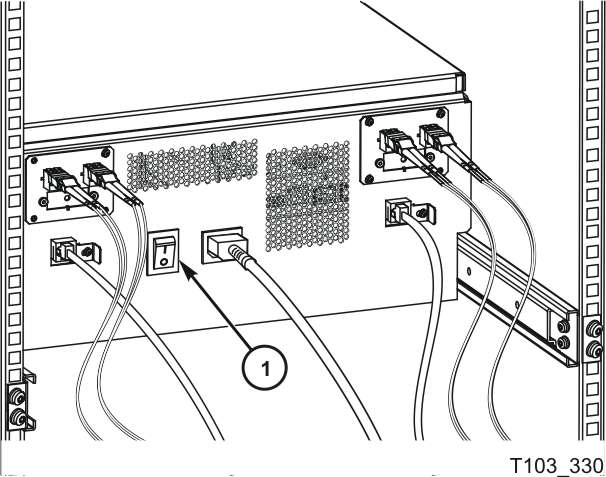
Figure 2-3 shows the rear of the rack mount chassis. One AC power connector and one AC switch supplies AC power to both drive power supplies, which are mounted internally, between the drives.
Illustration Legend:
1 - AC power switch
Note:
The drive status indicator and encryption status indicator, for encryption-capable drives, are visible through the drive cooling grids (does not apply to the T10000D tape drive).

