11 Maintaining Oracle Big Data Appliance
This chapter describes how to monitor and maintain Oracle Big Data Appliance. Some procedures use the dcli utility to execute commands in parallel on all servers.
This chapter contains the following sections:
See Also:
Chapter 13, "Using the dcli Utility"11.1 Monitoring the Ambient Temperature of Servers
Maintaining environmental temperature conditions within design specification for a server helps to achieve maximum efficiency and targeted component service lifetimes. Temperatures outside the ambient temperature range of 21 to 23 degrees Celsius (70 to 74 degrees Fahrenheit) affect all components within Oracle Big Data Appliance, possibly causing performance problems and shortened service lifetimes.
To monitor the ambient temperature:
-
Connect to an Oracle Big Data Appliance server as
root. -
Set up passwordless SSH for
rootby entering thesetup-root-sshcommand, as described in "Setting Up Passwordless SSH". -
Check the current temperature:
dcli 'ipmitool sunoem cli "show /SYS/T_AMB" | grep value'
-
If any temperature reading is outside the operating range, then investigate and correct the problem. See Table 2-11.
The following is an example of the command output:
bda1node01-adm.example.com: value = 22.000 degree C
bda1node02-adm.example.com: value = 22.000 degree C
bda1node03-adm.example.com: value = 22.000 degree C
bda1node04-adm.example.com: value = 23.000 degree C
          .
          .
          .
11.2 Powering On and Off Oracle Big Data Appliance
This section includes the following topics:
11.2.1 Nonemergency Power Procedures
This section contains the procedures for powering on and off the components of Oracle Big Data Appliance in an orderly fashion.
11.2.1.1 Powering On Oracle Big Data Appliance
Oracle Big Data Appliance is powered on by either pressing the power button on the front of the servers, or by logging in to the Oracle ILOM interface and applying power to the system.
To power on Oracle Big Data Appliance:
-
Turn on all 12 breakers on both PDUs.
Allow 4 to 5 minutes for Oracle ILOM to start.
-
Power up the servers.
11.2.1.2 Powering On Servers Remotely Using Oracle ILOM
You can power on the servers remotely using the Oracle ILOM interface. You can access Oracle ILOM using the web console, the command-line interface (CLI), the intelligent platform management interface (IPMI), or the simple network management protocol interface (SNMP). For example, to apply power to server bda1node01 using IPMI, run the following command as root from a server that has ipmitool installed:
ipmitool -H bda1node01-c -U root chassis power on
In this example, bda1node01-c is the host name of Oracle ILOM for the server to be powered on. You are prompted for the password.
11.2.1.3 Powering Off Oracle Big Data Appliance
To power off Oracle Big Data Appliance:
-
Power off the servers.
-
Turn off all 12 breakers on both PDUs.
11.2.1.3.1 Powering Off the Servers
Use the Linux shutdown command to power off or restart the servers. Enter this command as root to shut down a server immediately:
# shutdown -hP now
The following command restarts a server immediately:
# shutdown -r now
See Also:
Linux SHUTDOWN manual page for details11.2.1.3.2 Powering Off Multiple Servers at the Same Time
Use the dcli utility to run the shutdown command on multiple servers at the same time. Do not run the dcli utility from a server that will be shut down. Set up passwordless SSH for root, as described in "Setting Up Passwordless SSH".
The following command shows the syntax of the command:
# dcli -l root -g group_name shutdown -hP now
In this command, group_name is a file that contains a list of servers.
The following example shuts down all Oracle Big Data Appliance servers listed in the server_group file:
# dcli -l root -g server_group shutdown -hP now
See Also:
Chapter 13, "Using the dcli Utility"11.2.1.4 Powering On and Off Network Switches
The network switches do not have power switches. They power off when power is removed by turning off a PDU or a breaker in the data center.
11.2.2 Emergency Power-Off Considerations
In an emergency, halt power to Oracle Big Data Appliance immediately. The following emergencies may require powering off Oracle Big Data Appliance:
-
Natural disasters such as earthquake, flood, hurricane, tornado, or cyclone
-
Abnormal noise, smell, or smoke coming from the system
-
Threat to human safety
11.2.2.1 Emergency Power-Off Procedure
To perform an emergency power-off procedure for Oracle Big Data Appliance, turn off power at the circuit breaker or pull the emergency power-off switch in the computer room. After the emergency, contact Oracle Support Services to restore power to the system.
11.2.2.2 Emergency Power-Off Switch
Emergency power-off (EPO) switches are required when computer equipment contains batteries capable of supplying more than 750 volt-amperes for more than 5 minutes. Systems that have these batteries include internal EPO hardware for connection to a site EPO switch or relay. Use of the EPO switch removes power from Oracle Big Data Appliance.
11.2.3 Cautions and Warnings
The following cautions and warnings apply to Oracle Big Data Appliance:
WARNING:
Do not touch the parts of this product that use high-voltage power. Touching them might result in serious injury.
Caution:
-
Do not power off Oracle Big Data Appliance unless there is an emergency. In that case, follow the "Emergency Power-Off Procedure".
-
Keep the front and rear cabinet doors closed. Failure to do so might cause system failure or result in damage to hardware components.
-
Keep the top, front, and back of the cabinets clear to allow proper airflow and prevent overheating of components.
-
Use only the supplied hardware.
11.3 Adding Memory to the Servers
You can add memory to all servers in the cluster or to specific servers that need more memory, such as the two NameNodes.
11.3.1 Adding Memory to a Sun Server X4-2L or Sun Server X3-2L
Oracle Big Data Appliance X4-2 and X3-2 ship from the factory with 64 GB of memory in each server. Eight of the 16 DIMM slots are populated with 8 GB DIMMs.
These appliances support 8 GB, 16 GB, and 32 GB DIMMs. You can expand the amount of memory for a maximum of 512 GB (16 x 32 GB) in a server.
You can mix DIMM sizes, but they must be installed in order from largest to smallest. You can achieve the best performance by preserving symmetry. For example, add four of the same size DIMMs, one for each memory channel, to each processor, and ensure that both processors have the same size DIMMs installed in the same order.
To add memory to a Sun Server X4-2L or Sun Server X3-2L:
-
If you are mixing DIMM sizes, then review the DIMM population rules in the Sun Server X3-2L Service Manual at
http://docs.oracle.com/cd/E23393_01/html/E27229/ceiehcdb.html#scrolltoc -
Power down the server.
-
Install the new DIMMs. If you are installing 16 or 32 GB DIMMs, then replace the existing 8 GB DIMMs first, and then replace the plastic fillers. You must install the largest DIMMs first, then the next largest, and so forth. You can reinstall the original 8 GB DIMMs last.
See the Sun Server X3-2L Service Manual at
http://docs.oracle.com/cd/E23393_01/html/E27229/ceicjagi.html#scrolltoc -
Power on the server.
11.3.2 Adding Memory to Sun Fire X4270 M2 Servers
Oracle Big Data Appliance ships from the factory with 48 GB of memory in each server. Six of the 18 DIMM slots are populated with 8 GB DIMMs. You can populate the empty slots with 8 GB DIMMs to bring the total memory to either 96 GB (12 x 8 GB) or 144 GB (18 x 8 GB). An upgrade to 144 GB may slightly reduce performance because of lower memory bandwidth; memory frequency drops from 1333 MHz to 800 MHz.
To add memory to a Sun Fire X4270 M2 server:
-
Power down the server.
-
Replace the plastic fillers with the DIMMs. See the Sun Fire X4270 M2 Server Service Manual at
http://docs.oracle.com/cd/E19245-01/E21671/motherboard.html#50503715_71311 -
Power on the server.
11.4 Maintaining the Physical Disks of Servers
Repair of the physical disks does not require shutting down Oracle Big Data Appliance. However, individual servers can be taken outside of the cluster temporarily and require downtime.
See Also:
"Parts for Oracle Big Data Appliance Servers" for the repair procedures11.4.1 Verifying the Server Configuration
The 12 disk drives in each Oracle Big Data Appliance server are controlled by an LSI MegaRAID SAS 92610-8i disk controller. Oracle recommends verifying the status of the RAID devices to avoid possible performance degradation or an outage. The effect on the server of validating the RAID devices is minimal. The corrective actions may affect operation of the server and can range from simple reconfiguration to an outage, depending on the specific issue uncovered.
11.4.1.1 Verifying Disk Controller Configuration
Enter this command to verify the disk controller configuration:
# MegaCli64 -AdpAllInfo -a0 | grep "Device Present" -A 8
The following is an example of the output from the command. There should be 12 virtual drives, no degraded or offline drives, and 14 physical devices. The 14 devices are the controllers and the 12 disk drives.
                Device Present
                ================
Virtual Drives    : 12
  Degraded        : 0
  Offline         : 0
Physical Devices  : 14
  Disks           : 12
  Critical Disks  : 0
  Failed Disks    : 0
If the output is different, then investigate and correct the problem.
11.4.1.2 Verifying Virtual Drive Configuration
Enter this command to verify the virtual drive configuration:
# MegaCli64 -LDInfo -lAll -a0
The following is an example of the output for Virtual Drive 0. Ensure that State is Optimal.
Adapter 0 -- Virtual Drive Information:
Virtual Drive: 0 (Target Id: 0)
Name                :
RAID Level          : Primary-0, Secondary-0, RAID Level Qualifier-0
Size                : 1.817 TB
Parity Size         : 0
State               : Optimal
Strip Size          : 64 KB
Number Of Drives    : 1
Span Depth          : 1
Default Cache Policy: WriteBack, ReadAheadNone, Cached, No Write Cache if Bad BBU
Current Cache Policy: WriteBack, ReadAheadNone, Cached, No Write Cache if Bad BBU
Access Policy       : Read/Write
Disk Cache Policy   : Disk's Default
Encryption Type     : None
11.4.1.3 Verifying Physical Drive Configuration
Use the following command to verify the physical drive configuration:
# MegaCli64 -PDList -a0 | grep Firmware
The following is an example of the output from the command. The 12 drives should be Online, Spun Up. If the output is different, then investigate and correct the problem.
Firmware state: Online, Spun Up
Device Firmware Level: 061A
Firmware state: Online, Spun Up
Device Firmware Level: 061A
Firmware state: Online, Spun Up
Device Firmware Level: 061A
     .
     .
     .
11.5 Replacing a Server Disk
The failure of a disk is never catastrophic on Oracle Big Data Appliance. No user data should be lost. Data stored in HDFS or Oracle NoSQL Database is automatically replicated.
This section contains the following topics:
11.5.1 Overview of the Disk Replacement Process
The following are the basic steps for replacing a server disk drive:
-
Replace the failed disk drive.
-
Perform the basic configuration steps for the new disk.
-
Identify the dedicated function of the failed disk, as an operating system disk, or as either an HDFS disk or an Oracle NoSQL Database disk.
-
Configure the disk for its dedicated function.
-
Verify that the configuration is correct.
-
Install the Oracle Big Data Appliance software.
See Also:
"Servicing Storage Drives and Rear Drives" in the Sun Server X3-2L Service Manual at
http://docs.oracle.com/cd/E23393_01/html/E27229/z40000091011460.html
"Servicing Storage Drives and Boot Drives" in the Sun Fire X4270M2 Server Service Manual at
http://docs.oracle.com/cd/E19245-01/E21671/hotswap.html#50503714_61628
11.5.2 About Disk Drive Identifiers
The Oracle Big Data Appliance servers contain a disk enclosure cage that is controlled by the host bus adapter (HBA). The enclosure holds 12 disk drives that are identified by slot numbers 0 to 11. The drives can be dedicated to specific functions, as shown in Table 11-1.
Oracle Big Data Appliance uses symbolic links, which are defined in /dev/disk/by_hba_slot, to identify the slot number of a disk. The links have the form snpm, where n is the slot number and m is the partition number. For example, /dev/disk/by_hba_slot/s0p1 initially corresponds to /dev/sda1.
When a disk is hot swapped, the operating system cannot reuse the kernel device name. Instead, it allocates a new device name. For example, if you hot swap /dev/sda, then the disk corresponding /dev/disk/by-hba-slot/s0 might link to /dev/sdn instead of /dev/sda. Therefore, the links in /dev/disk/by-hba-slot/ are automatically updated when devices are added or removed.
The command output lists device names as kernel device names instead of symbolic link names. Thus, /dev/disk/by-hba-slot/s0 might be identified as /dev/sda in the output of a command.
11.5.2.1 Standard Disk Drive Mappings
Table 11-1 shows the mappings between the RAID logical drives and the operating system identifiers, and the dedicated function of each drive in an Oracle Big Data Appliance server. Nonetheless, you must confirm that these mappings are correct on your system. The server with the failed drive is part of either a CDH cluster (HDFS) or an Oracle NoSQL Database cluster.
Table 11-1 Disk Drive Identifiers
| Symbolic Link to Physical Slot | Initial Operating System Location | Dedicated Function |
|---|---|---|
|
/dev/disk/by-hba-slot/s0 |
/dev/sda |
Operating system |
|
/dev/disk/by-hba-slot/s1 |
/dev/sdb |
Operating system |
|
/dev/disk/by-hba-slot/s2 |
/dev/sdc |
HDFS or Oracle NoSQL Database |
|
/dev/disk/by-hba-slot/s3 |
/dev/sdd |
HDFS or Oracle NoSQL Database |
|
/dev/disk/by-hba-slot/s4 |
/dev/sde |
HDFS or Oracle NoSQL Database |
|
/dev/disk/by-hba-slot/s5 |
/dev/sdf |
HDFS or Oracle NoSQL Database |
|
/dev/disk/by-hba-slot/s6 |
/dev/sdg |
HDFS or Oracle NoSQL Database |
|
/dev/disk/by-hba-slot/s7 |
/dev/sdh |
HDFS or Oracle NoSQL Database |
|
/dev/disk/by-hba-slot/s8 |
/dev/sdi |
HDFS or Oracle NoSQL Database |
|
/dev/disk/by-hba-slot/s9 |
/dev/sdj |
HDFS or Oracle NoSQL Database |
|
/dev/disk/by-hba-slot/s10 |
/dev/sdk |
HDFS or Oracle NoSQL Database |
|
/dev/disk/by-hba-slot/s11 |
/dev/sdl |
HDFS or Oracle NoSQL Database |
11.5.2.2 Standard Mount Points
Table 11-2 show the mappings between HDFS partitions and mount points.
| Symbolic Link to Physical Slot and Partition | HDFS Partition | Mount Point |
|---|---|---|
|
/dev/disk/by-hba-slot/s0p4 |
/dev/sda4 |
/u01 |
|
/dev/disk/by-hba-slot/s1p4 |
/dev/sdb4 |
/u02 |
|
/dev/disk/by-hba-slot/s2p1 |
/dev/sdc1 |
/u03 |
|
/dev/disk/by-hba-slot/s3p1 |
/dev/sdd1 |
/u04 |
|
/dev/disk/by-hba-slot/s4p1 |
/dev/sde1 |
/u05 |
|
/dev/disk/by-hba-slot/s5p1 |
/dev/sdf1 |
/u06 |
|
/dev/disk/by-hba-slot/s6p1 |
/dev/sdg1 |
/u07 |
|
/dev/disk/by-hba-slot/s7p1 |
/dev/sdh1 |
/u08 |
|
/dev/disk/by-hba-slot/s8p1 |
/dev/sdi1 |
/u09 |
|
/dev/disk/by-hba-slot/s9p1 |
/dev/sdj1 |
/u10 |
|
/dev/disk/by-hba-slot/s10p1 |
/dev/sdk1 |
/u11 |
|
/dev/disk/by-hba-slot/s11p1 |
/dev/sdl1 |
/u12 |
11.5.2.3 Obtaining the Physical Slot Number of a Disk Drive
Use the following MegaCli64 command to verify the mapping of virtual drive numbers to physical slot numbers. See "Replacing a Disk Drive."
# MegaCli64 LdPdInfo a0 | more
11.5.3 Prerequisites for Replacing a Working or Failing Disk
If you plan to replace an HDFS disk or an operating system disk before it fails completely, then you should first dismount the HDFS partitions. You must also turn off swapping before replacing an operating system disk.
Note:
Only dismount HDFS partitions. For an operating system disk, ensure that you do not dismount operating system partitions. Only partition 4 (sda4 or sdb4) of an operating system disk is used for HDFS.To dismount HDFS partitions:
-
Log in to the server with the failing drive.
-
If the failing drive supported the operating system, then turn off swapping:
# bdaswapoff
Removing a disk with active swapping crashes the kernel.
-
List the mounted HDFS partitions:
# mount -l /dev/md2 on / type ext3 (rw,noatime) proc on /proc type proc (rw) sysfs on /sys type sysfs (rw) devpts on /dev/pts type devpts (rw,gid=5,mode=620) /dev/md0 on /boot type ext3 (rw) tmpfs on /dev/shm type tmpfs (rw) /dev/sda4 on /u01 type ext4 (rw,nodev,noatime) [/u01] /dev/sdb4 on /u02 type ext4 (rw,nodev,noatime) [/u02] /dev/sdc1 on /u03 type ext4 (rw,nodev,noatime) [/u03] /dev/sdd1 on /u04 type ext4 (rw,nodev,noatime) [/u04] . . . -
Check the list of mounted partitions for the failing disk. If the disk has no partitions listed, then proceed to "Replacing a Disk Drive." Otherwise, continue to the next step.
Caution:
For operating system disks, look for partition 4 (sda4 or sdb4). Do not dismount an operating system partition. -
Dismount the HDFS mount points for the failed disk:
# umount mountpointFor example,
umount /u11removes the mount point for partition /dev/sdk1.If the
umountcommands succeed, then proceed to "Replacing a Disk Drive." If aumountcommand fails with a device busy message, then the partition is still in use. Continue to the next step. -
Open a browser window to Cloudera Manager. For example:
http://bda1node03.example.com:7180 -
Complete these steps in Cloudera Manager:
-
Log in as
admin. -
On the Services page, click hdfs
-
Click the Instances subtab.
-
In the Host column, locate the server with the failing disk. Then click the service in the Name column, such as datanode, to open its page.
-
Click the Configuration subtab.
-
Remove the mount point from the Directory field.
-
Click Save Changes.
-
From the Actions list, choose Restart this DataNode.
Note:
If you removed the mount point in Cloudera Manager, then you must restore the mount point in Cloudera Manager after finishing all other configuration procedures. -
-
Return to your session on the server with the failed drive.
-
Reissue the
umountcommand:# umount mountpoint -
Complete the steps in "Replacing a Disk Drive."
11.5.4 What If a Server Fails to Restart?
The server may restart during the disk replacement procedures, either because you issued a reboot command or made an error in a MegaCli64 command. In most cases, the server restarts successfully, and you can continue working. However, in other cases, an error occurs so that you cannot reconnect using ssh. In this case, you must complete the reboot using Oracle ILOM.
To restart a server using Oracle ILOM:
-
Use your browser to open a connection to the server using Oracle ILOM. For example:
http://bda1node12-c.example.comNote:
Your browser must have a JDK plug-in installed. If you do not see the Java coffee cup on the log-in page, then you must install the plug-in before continuing. -
Log in using your Oracle ILOM credentials.
-
Select the Remote Control tab.
-
Click the Launch Remote Console button.
-
Enter Ctrl+d to continue rebooting.
-
If the reboot fails, then enter the server
rootpassword at the prompt and attempt to fix the problem. -
After the server restarts successfully, open the Redirection menu and choose Quit to close the console window.
See Also:
Oracle Integrated Lights Out Manager (ILOM) 3.0 documentation at11.5.5 Replacing a Disk Drive
Complete this procedure for all failed disk drives.
-
If you are replacing a working disk, then see "Prerequisites for Replacing a Working or Failing Disk."
-
Replace the failed disk drive.
-
Power on the server if you powered it off to replace the failed disk.
-
Connect to the server as
rootusing either the KVM or an SSL connection to a laptop. -
Store the physical drive information in a file:
# MegaCli64 pdlist a0 > pdinfo.tmp
Note: This command redirects the output to a file so that you can perform several searches using a text editor. If you prefer, you can pipe the output through the
moreorgrepcommands.The utility returns the following information for each slot. This example shows a Firmware State of
Unconfigured(good), Spun Up.Enclosure Device ID: 20 Slot Number: 8 Drive's postion: DiskGroup: 8, Span: 0, Arm: 0 Enclosure position: 0 Device Id: 11 WWN: 5000C5003487075C Sequence Number: 2 Media Error Count: 0 Other Error Count: 0 Predictive Failure Count: 0 Last Predictive Failure Event Seq Number: 0 PD Type: SAS Raw Size: 1.819 TB [0xe8e088b0 Sectors] Non Coerced Size: 1.818 TB [0xe8d088b0 Sectors] Coerced Size: 1.817 TB [0xe8b6d000 Sectors] Firmware state: Unconfigured(good), Spun Up Is Commissioned Spare : NO Device Firmware Level: 061A Shield Counter: 0 Successful diagnostics completion on : N/A SAS Address(0): 0x5000c5003487075d SAS Address(1): 0x0 Connected Port Number: 0(path0) Inquiry Data: SEAGATE ST32000SSSUN2.0T061A1126L6M3WX FDE Enable: Disable Secured: Unsecured Locked: Unlocked Needs EKM Attention: No Foreign State: None Device Speed: 6.0Gb/s Link Speed: 6.0Gb/s Media Type: Hard Disk Device . . .
-
Open the file you created in Step 5 in a text editor and search for the following:
-
For disks that have a Foreign State of Foreign, clear that status:
# MegaCli64 CfgForeign clear a0
A foreign disk is one that the controller saw previously, such as a reinserted disk.
-
For disks that have a Firmware State of Unconfigured (Bad), complete these steps:
-
Note the enclosure device ID number and the slot number.
-
Enter a command in this format:
# MegaCli64 pdmakegood physdrv[enclosure:slot] a0For example, [20:10] repairs the disk identified by enclosure 20 in slot 10.
-
Check the current status of Foreign State again:
# MegaCli64 pdlist a0 | grep foreign
-
If the Foreign State is still Foreign, then repeat the
clearcommand:# MegaCli64 CfgForeign clear a0
-
-
For disks that have a Firmware State of Unconfigured (Good), use the following command. If multiple disks are unconfigured, then configure them in order from the lowest to the highest slot number:
# MegaCli64 CfgLdAdd r0[enclosure:slot] a0

Adapter 0: Created VD 1

Adapter 0: Configured the Adapter!!

Exit Code: 0x00
For example, [20:5] repairs the disk identified by enclosure 20 in slot 5.
-
If the
CfgLdAddcommand in Step 9 fails because of cached data, then clear the cache:# MegaCli64 discardpreservedcache l1 a0
-
Verify that the disk is recognized by the operating system:
# lsscsi
The disk may appear with its original device name (such as /dev/sdc) or under a new device name (such as /dev/sdn). If the operating system does not recognize the disk, then the disk is missing from the list generated by the
lsscsicommand.The
lsscioutput might not show the correct order, but you can continue with the configuration. While the same physical to logical disk mapping is required, the same disk to device mapping for the kernel is not required. The disk configuration is based on /dev/disks/by-hbda-slot device names.This example output shows two disks with new device names: /dev/sdn in slot 5, and /dev/sdo in slot 10.
[0:0:20:0]   enclosu ORACLE  CONCORD14        0960  -
[0:2:0:0]    disk    LSI      MR9261-8i        2.12  /dev/sda
[0:2:1:0]    disk    LSI      MR9261-8i        2.12  /dev/sdb
[0:2:2:0]    disk    LSI      MR9261-8i        2.12  /dev/sdc
[0:2:3:0]    disk    LSI      MR9261-8i        2.12  /dev/sdd
[0:2:4:0]    disk    LSI      MR9261-8i        2.12  /dev/sde
[0:2:5:0]    disk    LSI      MR9261-8i        2.12  /dev/sdn
[0:2:6:0]    disk    LSI      MR9261-8i        2.12  /dev/sdg
[0:2:7:0]    disk    LSI      MR9261-8i        2.12  /dev/sdh
[0:2:8:0]    disk    LSI      MR9261-8i        2.12  /dev/sdi
[0:2:9:0]    disk    LSI      MR9261-8i        2.12  /dev/sdj
[0:2:10:0]   disk    LSI      MR9261-8i        2.12  /dev/sdo
[0:2:11:0]   disk    LSI      MR9261-8i        2.12  /dev/sdl
[7:0:0:0]    disk    ORACLE   UNIGEN-UFD       PMAP  /dev/sdm
[
-
Check the hardware profile of the server, and correct any errors:
# bdacheckhw
-
Check the software profile of the server, and correct any errors:
# bdachecksw
If the mounted partitions check fails, then see "Correcting a Mounted Partitions Error.".
-
Identify the function of the drive, so you configure it properly. See "Identifying the Function of a Disk Drive."
11.5.6 Correcting a Mounted Partitions Error
When the bdachecksw utility finds a problem, it typically concerns the mounted partitions.
An old mount point might appear in the mount command output, so that the same mount point, such as /u03, appears twice.
To fix duplicate mount points:
-
Dismount both mount points by using the
umountcommand twice. This example dismounts two instances of/u03:# umount /u03 # umount /u03
-
Remount the mount point. This example remounts /u03:
# mount /u03
If a disk is in the wrong slot (that is, the virtual drive number), then you can switch two drives.
To switch slots:
-
Remove the mappings for both drives. This example removes the drives from slots 4 and 10:
# MegaCli64 cfgLdDel L4 a0
# MegaCli64 cfgLdDel L10 a0
-
Add the drives in the order you want them to appear; the first command obtains the first available slot number:
# MegaCli64 cfgLdAdd [20:4] a0
# MegaCli64 cfgLdAdd [20:5] a0
-
If mount errors persist even when the slot numbers are correct, then you can restart the server.
11.5.7 Identifying the Function of a Disk Drive
The server with the failed disk is configured to support either HDFS or Oracle NoSQL Database, and most disks are dedicated to that purpose. However, two disks are dedicated to the operating system. Before configuring the new disk, find out how the failed disk was configured.
11.5.7.1 Checking for Use by the Operating System
Oracle Big Data Appliance is configured with the operating system on the first two disks.
To confirm that a failed disk supported the operating system:
-
Check whether the replacement disk corresponds to /dev/sda or /dev/sdb, which are the operating system disks.
# lsscsi
See the output from Step 11 of "Replacing a Disk Drive".
-
Verify that /dev/sda and /dev/sdb are the operating system mirrored partitioned disks:
# mdadm -Q –-detail /dev/md2 /dev/md2: Version : 0.90 Creation Time : Mon Jul 22 22:56:19 2013 Raid Level : raid1 . . . Number Major Minor RaidDevice State 0 8 2 0 active sync /dev/sda2 1 8 18 1 active sync /dev/sdb2 -
If the previous steps indicate that the failed disk is an operating system disk, then proceed to "Configuring an Operating System Disk."
11.5.8 Configuring an Operating System Disk
The first two disks support the Linux operating system. These disks store a copy of the mirrored operating system, a swap partition, a mirrored boot partition, and an HDFS data partition.
To configure an operating system disk, you must copy the partition table from the surviving disk, create an HDFS partition (ext4 file system), and add the software raid partitions and boot partitions for the operating system.
Complete these procedures after replacing the disk in either slot 0 or slot 1.
11.5.8.1 Partitioning the Operating System Disk
Note:
Replace /dev/disk/by-hba-slot/sn in the following commands with the appropriate symbolic link, either /dev/disk/by-hba-slot/s0 or /dev/disk/by-hba-slot/s1.-
Complete the steps in "Replacing a Disk Drive."
-
Confirm that the new disk does not have a partition table:
# parted /dev/disk/by-hba-slot/sn -s printYou should see a message about a missing partition table.
-
If the
partedcommand displays a partition table, then clear it:# dd if=/dev/zero of=/dev/disk/by-hba-slot/sn bs=1M count=100Tip:
You can use this command to restart an operating system disk configuration, if you make a mistake. -
Create the partition table:
# parted /dev/disk/by-hba-slot/sn -s mklabel gpt print -
List the Cylinder, Head, Sector (CHS) partition information of the surviving disk. Thus, if you are partitioning /dev/disk/by-hba-slot/s0, then enter /dev/disk/by-hba-slot/s1 for /dev/disk/by-hba-slot/sm in the following command:
# parted /dev/disk/by-hba-slot/sm -s unit chs print

Model: LSI MR9261-8i (scsi)
Disk /dev/sda: 243031,30,6
Sector size (logical/physical): 512B/512B
BIOS cylinder,head,sector geometry: 243031,255,63.  Each cylinder is 8225kB.
Partition Table: gpt

Number  Start         End           File system  Name     Flags
 1      0,0,34        25,127,7      ext3                  raid
 2      25,127,8      21697,116,20  ext3                  raid
 3      21697,116,21  23227,61,35   linux-swap
 4      23227,61,36   243031,29,36  ext3         primary
-
Create partitions 1 to 3 on the new drive by duplicating the partitions of the surviving disk. Issue three commands in this format:
# parted /dev/disk/by-hba-slot/sn -s mkpart file_system start end
Use the start and end addresses that you obtained in Step 5 instead of the addresses shown in the following example:
# parted /dev/disk/by-hba-slot/sn -s mkpart ext3 0,0,34 25,127,7
# parted /dev/disk/by-hba-slot/sn -s mkpart ext3 25,127,8 21697,116,20
# parted /dev/disk/by-hba-slot/sn -s mkpart linux-swap 21697,116,21 23227,61,35
-
Create primary partition 4 using the start address obtained in Step 5 and an end address of 100%:
# parted /dev/disk/by-hba-slot/sn -s mkpart primary ext3 23227,61,36 100%Partition 4 stores HDFS data, and this syntax makes the partition as large as possible.
-
Set the RAID flags:
# parted -s /dev/disk/by-hba-slot/sn set 1 raid
# parted -s /dev/disk/by-hba-slot/sn set 2 raid
-
Clear the names, using
partedin interactive mode:# parted /dev/disk/by-hba-slot/sn GNU Parted 1.8.1 Using /dev/sdn Welcome to GNU Parted! Type 'help' to view a list of commands. (parted) name 1 " " (parted) name 2 " " (parted) name 3 " " (parted) quit
-
Complete the steps in "Repairing the RAID Arrays".
11.5.8.2 Repairing the RAID Arrays
After partitioning the disks, you can repair the two logical RAID arrays:
-
/dev/md0 contains /dev/disk/by-hba-slot/s0p1 and /dev/disk/by-hba-slot/s1p1. It is mounted as /boot.
-
/dev/md2 contains /dev/disk/by-hba-slot/s0p2and /dev/disk/by-hba-slot/s1p2. It is mounted as / (root).
Caution:
Do not dismount the /dev/md devices, because that action shuts down the system.To repair the RAID arrays:
-
Remove the partitions from the RAID arrays:
# mdadm /dev/md0 -r detached
# mdadm /dev/md2 -r detached
-
Verify that the RAID arrays are degraded:
# mdadm -Q –-detail /dev/md0
# mdadm -Q –-detail /dev/md2
-
Verify that the degraded file for each array is set to 1:
# cat /sys/block/md0/md/degraded
1
# cat /sys/block/md2/md/degraded
1
-
Restore the partitions to the RAID arrays:
# mdadm –-add /dev/md0 /dev/disk/by-hba-slot/snp1
# mdadm –-add /dev/md2 /dev/disk/by-hba-slot/snp2
-
Check that resynchronization is started, so that /dev/md2 is in a state of recovery and not idle:
# cat /sys/block/md2/md/sync_action repair -
To verify that resynchronization is proceeding, you can monitor the mdstat file. A counter identifies the percentage complete.
# cat /proc/mdstat

Personalities : [raid1]
md0 : active raid1 sdb1[1] sda1[0]
      204736 blocks [2/2] [UU]

md2 : active raid1 sdb2[2] sda2[0]
      174079936 blocks [2/1] [U_]
      [============>........]  recovery = 61.6% (107273216/174079936) finish=18.4min speed=60200K/sec
The following output shows that synchronization is complete:
Personalities : [raid1] md0 : active raid1 sdb1[1] sda1[0] 204736 blocks [2/2] [UU] md2 : active raid1 sdb2[1] sda2[0] 174079936 blocks [2/2] [UU] unused devices: <none> -
Display the content of /etc/mdadm.conf:
# cat /etc/mdadm.conf # mdadm.conf written out by anaconda DEVICE partitions MAILADDR root ARRAY /dev/md0 level=raid1 num-devices=2 UUID=df1bd885:c1f0f9c2:25d6... ARRAY /dev/md2 level=raid1 num-devices=2 UUID=6c949a1a:1d45b778:a6da... -
Compare the output of the following command with the content of /etc/mdadm.conf from Step 7:
# mdadm --examine --brief --scan --config=partitions
-
If the UUIDs in the file are different from UUIDs in the output of the
mdadmcommand:-
Open /etc/mdadm.conf in a text editor.
-
Select from ARRAY to the end of the file, and delete the selected lines.
-
Copy the output of the command into the file where you deleted the old lines.
-
Save the modified file and exit.
-
-
Complete the steps in "Formatting the HDFS Partition of an Operating System Disk".
11.5.8.3 Formatting the HDFS Partition of an Operating System Disk
Partition 4 (sda4) on an operating system disk is used for HDFS. After you format the partition and set the correct label, HDFS rebalances the job load to use the partition if the disk space is needed.
To format the HDFS partition:
-
Format the HDFS partition as an ext4 file system:
# mke4fs -t ext4 /dev/disk/by-hba-slot/snp4

mke4fs 1.41.12 (17-May-2010)
Filesystem label=
OS type: Linux
Block size=4096 (log=2)
Fragment size=4096 (log=2)
Stride=0 blocks, Stripe width=0 blocks
110354432 inodes, 441393655 blocks
22069682 blocks (5.00%) reserved for the super user
First data block=0
Maximum filesystem blocks=4294967296
13471 block groups
32768 blocks per group, 32768 fragments per group
8192 inodes per group
Superblock backups stored on blocks:
        32768, 98304, 163840, 229376, 294912, 819200, 884736, 1605632, 2654208,
        4096000, 7962624, 11239424, 20480000, 23887872, 71663616, 78675968,
        102400000, 214990848

Writing inode tables:
Note:
If this command fails because the device is mounted, then dismount the drive now and skip step 3. See "Prerequisites for Replacing a Working or Failing Disk" for dismounting instructions. -
Verify that the partition label (such as /u01 for s0p4) is missing:
# ls -l /dev/disk/by-label
-
Dismount the appropriate HDFS partition, either /u01 for /dev/sda, or /u02 for /dev/sdb:
# umount /u0n -
Reset the partition label:
# tune4fs -c -1 -i 0 -m 0.2 -L /u0n /dev/disk/by-hba-slot/snp4
-
Mount the HDFS partition:
# mount /u0n -
Complete the steps in "Restoring the Swap Partition".
11.5.8.4 Restoring the Swap Partition
After formatting the HDFS partition, you can restore the swap partition.
To restore the swap partition:
-
Set the swap label:
# mkswap -L SWAP-sdn3 /dev/disk/by-hba-slot/snp3
Setting up swapspace version 1, size = 12582907 kB
LABEL=SWAP-sdn3, no uuid
-
Verify that the swap partition is restored:
# bdaswapon; bdaswapoff Filename Type Size Used Priority /dev/sda3 partition 12287992 0 1 /dev/sdb3 partition 12287992 0 1 -
Complete the steps in "Restoring the GRUB Master Boot Records and HBA Boot Order".
11.5.8.5 Restoring the GRUB Master Boot Records and HBA Boot Order
After restoring the swap partition, you can restore the Grand Unified Bootloader (GRUB) master boot record.
To restore the GRUB boot record:
-
Open GRUB:
# grub --device-map=/boot/grub/device.map

    GNU GRUB  version 0.97  (640K lower / 3072K upper memory)

 [ Minimal BASH-like line editing is supported.  For the first word, TAB
   lists possible command completions.  Anywhere else TAB lists the possible
   completions of a device/filename.
]
The device.map file maps the BIOS drives to operating system devices. The following is an example of a device map file:
# this device map was generated by anaconda
(hd0)     /dev/sda
(hd1)     /dev/sdb
-
Set the root device, entering hd0 for /dev/sda, or hd1 for /dev/sdb:
grub> root (hdn,0)

root (hdn,0)
 Filesystem type is ext2fs, partition type 0x83
-
Install grub, entering hd0 for /dev/sda, or hd1 for /dev/sdb:
grub> setup (hdn)

setup (hdn)
 Checking if "/boot/grub/stage1" exists... no
 Checking if "/grub/stage1" exists... yes
 Checking if "/grub/stage2" exists... yes
 Checking if "/grub/e2fs_stage1_5" exists... yes
 Running "embed /grub/e2fs_stage1_5 (hdn)"... failed (this is not fatal)
 Running "embed /grub/e2fs_stage1_5 (hdn,0)"... failed (this is not fatal)
 Running "install /grub/stage1 (hdn) /grub/stage2 p /grub/grub.conf "... succeeded
Done.
-
Close the GRUB command-line interface:
grub> quit -
Ensure that logical drive
L0(L + zero) is set as the boot drive in the HBA:# MegaCli64 -AdpBootDrive -get a0 Adapter 0: Boot Virtual Drive - #0 (target id - 0). -
If the previous command does not report
L0or virtual drive 0 target 0, then enter:# MegaCli64 AdpBootDrive set L0 a0 -
Ensure that the auto-select boot drive feature is enabled:
# MegaCli64 adpBIOS EnblAutoSelectBootLd a0 Auto select Boot is already Enabled on Adapter 0. -
Check the configuration. See "Verifying the Disk Configuration."
11.5.9 Configuring an HDFS or Oracle NoSQL Database Disk
Complete the following instructions for any disk that is not used by the operating system. See "Identifying the Function of a Disk Drive."
11.5.9.1 Partitioning a Disk for HDFS or Oracle NoSQL Database
To configure a disk, you must partition and format it.
Note:
Replace snp1 in the following commands with the appropriate symbolic name, such as s4p1.To format a disk for use by HDFS or Oracle NoSQL Database:
-
Complete the steps in "Replacing a Disk Drive," if you have not done so already.
-
Partition the drive:
# parted /dev/disk/by-hba-slot/sn -s mklabel gpt mkpart primary ext3 0% 100% -
Format the partition for an ext4 file system:
# mke4fs -t ext4 /dev/disk/by-hba-slot/snp1

mke4fs 1.41.12 (17-May-2010)
Filesystem label=
OS type: Linux
Block size=4096 (log=2)
Fragment size=4096 (log=2)
Stride=0 blocks, Stripe width=0 blocks
122011648 inodes, 488036855 blocks
24401842 blocks (5.00%) reserved for the super user
First data block=0
Maximum filesystem blocks=4294967296
14894 block groups
32768 blocks per group, 32768 fragments per group
8192 inodes per group
Superblock backups stored on blocks:
        32768, 98304, 163840, 229376, 294912, 819200, 884736, 1605632, 2654208,
        4096000, 7962624, 11239424, 20480000, 23887872, 71663616, 78675968,
        102400000, 214990848

Writing inode tables: done
Creating journal (32768 blocks): done
Writing superblocks and filesystem accounting information: done

This filesystem will be automatically checked every 23 mounts or
180 days, whichever comes first.  Use tune4fs -c or -i to override.
-
Reset the appropriate partition label to the missing device. See Table 11-2.
# tune4fs -c -1 -i 0 -m 0.2 -L /unn /dev/disk/by-hba-slot/snp1
For example, this command resets the label for /dev/disk/by-hba-slot/s2p1 to /u03:
# tune4fs -c -1 -i 0 -m 0.2 -L /u03 /dev/disk/by-hba-slot/s2p1
Setting maximal mount count to -1
Setting interval between checks to 0 seconds
Setting reserved blocks percentage to 0.2% (976073 blocks)
-
Mount the HDFS partition, entering the appropriate mount point:
# mount /unnFor example,
mount /u03. -
If you are configuring multiple drives, then repeat the previous steps.
-
If you previously removed a mount point in Cloudera Manager for an HDFS drive, then restore it to the list.
-
Open a browser window to Cloudera Manager. For example:
http://bda1node03.example.com:7180 -
Open Cloudera Manager and log in as
admin. -
On the Services page, click hdfs
-
Click the Instances subtab.
-
In the Host column, locate the server with the replaced disk. Then click the service in the Name column, such as datanode, to open its page.
-
Click the Configuration subtab.
-
If the mount point is missing from the Directory field, then add it to the list.
-
Click Save Changes.
-
From the Actions list, choose Restart.
-
-
Check the configuration. See "Verifying the Disk Configuration."
11.5.10 Verifying the Disk Configuration
Before you can reinstall the Oracle Big Data Appliance software on the server, you must verify that the configuration is correct on the new disk drive.
To verify the disk configuration:
-
Check the software configuration:
# bdachecksw
-
If there are errors, then redo the configuration steps as necessary to correct the problem.
-
Check the /root directory for a file named BDA_REBOOT_SUCCEEDED.
-
If you find a file named BDA_REBOOT_FAILED, then read the file to identify and fix any additional problems.
-
Use this script to generate a BDA_REBOOT_SUCCEEDED file:
# /opt/oracle/bda/lib/bdastartup.sh
-
Verify that BDA_REBOOT_SUCCEEDED exists. If you still find a BDA_REBOOT_FAILED file, then redo the previous steps.
11.6 Maintaining the InfiniBand Network
The InfiniBand network connects the servers through the bondib0 interface to the InfiniBand switches in the rack. This section describes how to perform maintenance on the InfiniBand switches.
This section contains the following topics:
11.6.1 Backing Up and Restoring Oracle ILOM Settings
Oracle ILOM supports remote administration of the Oracle Big Data Appliance servers. This section explains how to back up and restore the Oracle ILOM configuration settings, which are set by the Mammoth.
See Also:
Oracle Integrated Lights Out Manager 3.0 documentation at11.6.1.1 Backing Up the Oracle ILOM Configuration Settings
To back up the Oracle ILOM configuration settings:
-
Open your browser on any system that is on the same network as Oracle Big Data Appliance, and enter the Oracle ILOM address of a server. This example uses the Oracle ILOM address of node08:
http://bda1node08-c.example.com -
Log in as the
rootuser. The initial password iswelcome1. -
In the navigation tree, expand the ILOM Administration folder and select Configuration Management.
-
Select the Backup operation and the Browser transfer method, as shown in Figure 11-1.
-
Enter a pass phrase. The phrase is used to encrypt sensitive information, such as passwords, in the backup file.
-
Click Run to start the backup operation. The results are downloaded to your local system in an XML file named config_backup.xml.
-
Save the file in a secure location.
-
Click the Log Out button.
Figure 11-1 Oracle ILOM Configuration Backup
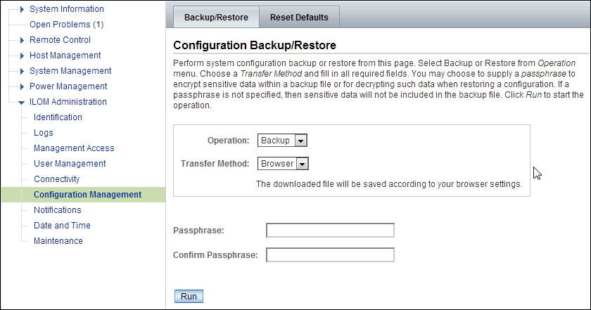
Description of "Figure 11-1 Oracle ILOM Configuration Backup"
11.6.1.2 Restoring Oracle ILOM Configuration Settings
To restore the Oracle ILOM configuration settings:
-
Open your browser on any system on the same network as Oracle Big Data Appliance and navigate to an Oracle ILOM service processor. This example uses Oracle ILOM on node08:
http://bda1node08-c.us.example.com -
Log in as the
ilom-adminuser. The default password iswelcome1. -
Select the Maintenance tab.
-
Select the Backup/Restore tab.
-
Select the Restore operation and the Browser transfer method.
-
Click Choose File and select the config_backup.xml file saved previously in a backup operation.
-
Enter the pass phrase that was set during the backup operation.
-
Click Run to restore the configuration.
11.6.2 Replacing a Failed InfiniBand Switch
Complete these steps to replace a Sun Network QDR InfiniBand Gateway switch or a Sun Datacenter InfiniBand Switch 36.
See Also:
-
"In-Rack InfiniBand Switch-to-Server Cable Connections" for information about cabling
-
Sun Network QDR InfiniBand Gateway Switch Installation Guide at
-
http://docs.oracle.com/cd/E26699_01/html/E26706/gentextid-125.html#scrolltoc -
Sun Datacenter InfiniBand Switch 36 User's Guide at
http://docs.oracle.com/cd/E26698_01/html/E26434/gentextid-119.html#scrolltoc
To replace a failed InfiniBand switch:
-
Disconnect the cables from the switch. All InfiniBand cables have labels at both ends indicating their locations. If any cables do not have labels, then label them.
-
Power off both power supplies on the switch by removing the power plugs.
-
Remove the switch from the rack.
-
Install the new switch in the rack.
-
Restore the switch settings using the backup file, as described in "Backing Up and Restoring Oracle ILOM Settings".
-
Connect to the switch as
ilom_adminand open the Fabric Management shell:-> show /SYS/Fabric_Mgmt
The prompt changes from -> to FabMan@hostname->
-
Disable the Subnet Manager:
FabMan@bda1sw-02-> disablesm
-
Connect the cables to the new switch, being careful to connect each cable to the correct port.
-
Verify that there are no errors on any links in the fabric:
FabMan@bda1sw-02-> ibdiagnet -c 1000 -r
-
Enable the Subnet Manager:
FabMan@bda1sw-02-> enablesm
Note:
If the replaced switch was the Sun Datacenter InfiniBand Switch 36 spine switch, then manually fail the master Subnet Manager back to the switch by disabling the Subnet Managers on the other switches until the spine switch becomes the master. Then reenable the Subnet Manager on all the other switches.
11.6.3 Verifying InfiniBand Network Operation
If any component in the InfiniBand network has required maintenance, including replacing an InfiniBand Host Channel Adapter (HCA) on a server, an InfiniBand switch, or an InfiniBand cable, or if operation of the InfiniBand network is suspected to be substandard, then verify that the InfiniBand network is operating properly. The following procedure describes how to verify network operation:
Note:
Use this procedure any time the InfiniBand network is performing below expectations.To verify InfiniBand network operation:
-
Enter the
ibdiagnetcommand to verify InfiniBand network quality:# ibdiagnet -c 1000
Investigate all errors reported by this command. It generates a small amount of network traffic and can run during a normal workload.
See Also:
Sun Network QDR InfiniBand Gateway Switch Command Reference athttp://docs.oracle.com/cd/E26699_01/html/E26706/gentextid-28027.html#scrolltoc -
Report switch port error counters and port configuration information. The
LinkDowned,RcvSwRelayErrors,XmtDiscards, andXmtWaiterrors are ignored by this command:# ibqueryerrors.pl -rR -s LinkDowned,RcvSwRelayErrors,XmtDiscards,XmtWait
See Also:
Linuxmanpage foribqueryerrors.S -
Check the status of the hardware:
# bdacheckhw
The following is an example of the output:
[SUCCESS: Correct system model : SUN FIRE X4270 M2 SERVER [SUCCESS: Correct processor info : Intel(R) Xeon(R) CPU X5675 @ 3.07GHz [SUCCESS: Correct number of types of CPU : 1 [SUCCESS: Correct number of CPU cores : 24 [SUCCESS: Sufficient GB of memory (>=48): 48 [SUCCESS: Correct GB of swap space : 24 [SUCCESS: Correct BIOS vendor : American Megatrends Inc. [SUCCESS: Sufficient BIOS version (>=08080102): 08080102 [SUCCESS: Recent enough BIOS release date (>=05/23/2011) : 05/23/2011 [SUCCESS: Correct ILOM version : 3.0.16.10.a r68533 [SUCCESS: Correct number of fans : 6 [SUCCESS: Correct fan 0 status : ok [SUCCESS: Correct fan 1 status : ok [SUCCESS: Correct fan 2 status : ok [SUCCESS: Correct fan 3 status : ok [SUCCESS: Correct fan 4 status : ok [SUCCESS: Correct fan 5 status : ok [SUCCESS: Correct number of power supplies : 2 [1m[34mINFO: Detected Santa Clara Factory, skipping power supply checks [SUCCESS: Correct disk controller model : LSI MegaRAID SAS 9261-8i [SUCCESS: Correct disk controller firmware version : 12.12.0-0048 [SUCCESS: Correct disk controller PCI address : 13:00.0 [SUCCESS: Correct disk controller PCI info : 0104: 1000:0079 [SUCCESS: Correct disk controller PCIe slot width : x8 [SUCCESS: Correct disk controller battery type : iBBU08 [SUCCESS: Correct disk controller battery state : Operational [SUCCESS: Correct number of disks : 12 [SUCCESS: Correct disk 0 model : SEAGATE ST32000SSSUN2.0 [SUCCESS: Sufficient disk 0 firmware (>=61A): 61A [SUCCESS: Correct disk 1 model : SEAGATE ST32000SSSUN2.0 [SUCCESS: Sufficient disk 1 firmware (>=61A): 61A . . . [SUCCESS: Correct disk 10 status : Online, Spun Up No alert [SUCCESS: Correct disk 11 status : Online, Spun Up No alert [SUCCESS: Correct Host Channel Adapter model : Mellanox Technologies MT26428 ConnectX VPI PCIe 2.0 [SUCCESS: Correct Host Channel Adapter firmware version : 2.9.1000 [SUCCESS: Correct Host Channel Adapter PCI address : 0d:00.0 [SUCCESS: Correct Host Channel Adapter PCI info : 0c06: 15b3:673c [SUCCESS: Correct Host Channel Adapter PCIe slot width : x8 [SUCCESS: Big Data Appliance hardware validation checks succeeded -
Check the status of the software:
# bdachecksw
[SUCCESS: Correct OS disk sda partition info : 1 ext3 raid 2 ext3 raid 3 linux-swap 4 ext3 primary
[SUCCESS: Correct OS disk sdb partition info : 1 ext3 raid 2 ext3 raid 3 linux-swap 4 ext3 primary
[SUCCESS: Correct data disk sdc partition info : 1 ext3 primary
[SUCCESS: Correct data disk sdd partition info : 1 ext3 primary
[SUCCESS: Correct data disk sde partition info : 1 ext3 primary
[SUCCESS: Correct data disk sdf partition info : 1 ext3 primary
[SUCCESS: Correct data disk sdg partition info : 1 ext3 primary
[SUCCESS: Correct data disk sdh partition info : 1 ext3 primary
[SUCCESS: Correct data disk sdi partition info : 1 ext3 primary
[SUCCESS: Correct data disk sdj partition info : 1 ext3 primary
[SUCCESS: Correct data disk sdk partition info : 1 ext3 primary
[SUCCESS: Correct data disk sdl partition info : 1 ext3 primary
[SUCCESS: Correct software RAID info : /dev/md2 level=raid1 num-devices=2 /dev/md0 level=raid1 num-devices=2
[SUCCESS: Correct mounted partitions : /dev/md0 /boot ext3 /dev/md2 / ext3 /dev/sda4 /u01 ext4 /dev/sdb4 /u02 ext4 /dev/sdc1 /u03 ext4 /dev/sdd1 /u04 ext4 /dev/sde1 /u05 ext4 /dev/sdf1 /u06 ext4 /dev/sdg1 /u07 ext4 /dev/sdh1 /u08 ext4 /dev/sdi1 /u09 ext4 /dev/sdj1 /u10 ext4 /dev/sdk1 /u11 ext4 /dev/sdl1 /u12 ext4
[SUCCESS: Correct swap partitions : /dev/sdb3 partition /dev/sda3 partition
[SUCCESS: Correct Linux kernel version : Linux 2.6.32-200.21.1.el5uek
[SUCCESS: Correct Java Virtual Machine version : HotSpot(TM) 64-Bit Server 1.6.0_29
[SUCCESS: Correct puppet version : 2.6.11
[SUCCESS: Correct MySQL version : 5.5.17
[SUCCESS: All required programs are accessible in $PATH
[SUCCESS: All required RPMs are installed and valid
[SUCCESS: Big Data Appliance software validation checks succeeded
11.6.4 Understanding the Network Subnet Manager Master
The Subnet Manager manages all operational characteristics of the InfiniBand network, such as the ability to:
-
Assign a local identifier to all ports connected to the network
-
Calculate and program switch forwarding tables
-
Monitor changes in the fabric
The InfiniBand network can have multiple Subnet Managers, but only one Subnet Manager is active at a time. The active Subnet Manager is the Master Subnet Manager. The other Subnet Managers are the Standby Subnet Managers. If a Master Subnet Manager is shut down or fails, then a Standby Subnet Manager automatically becomes the Master Subnet Manager.
Each Subnet Manager has a configurable priority. When multiple Subnet Managers are on the InfiniBand network, the Subnet Manager with the highest priority becomes the master Subnet Manager. On Oracle Big Data Appliance, the Subnet Managers on the leaf switches are configured as priority 5, and the Subnet Managers on the spine switches are configured as priority 8.
The following guidelines determine where the Subnet Managers run on Oracle Big Data Appliance:
-
Run the Subnet Managers only on the switches in Oracle Big Data Appliance. Running a Subnet Manager on any other device is not supported.
-
When the InfiniBand network consists of one, two, or three racks cabled together, all switches must run a Subnet Manager. The master Subnet Manager runs on a spine switch.
-
When the InfiniBand network consists of four or more racks cabled together, then only the spine switches run a Subnet Manager. The leaf switches must disable the Subnet Manager.
See Also:
-
Sun Network QDR InfiniBand Gateway Switch library at
-
Sun Datacenter InfiniBand Switch 36 library at
11.7 Changing the Number of Connections to a Gateway Switch
If you change the number of 10 GbE connections to a Sun Network QDR InfiniBand Gateway switch, then you must run thebdaredoclientnet utility. See "bdaredoclientnet."
To re-create the VNICs in a rack:
-
Verify that /opt/oracle/bda/BdaDeploy.json exists on all servers and correctly describes the custom network settings. This command identifies files that are missing or have different date stamps:
dcli ls -l /opt/oracle/bda/BdaDeploy.json
-
Connect to node01 (bottom of rack) using the administrative network. The
bdaredoclientnetutility shuts down the client network, so you cannot use it in this procedure. -
Remove passwordless SSH:
/opt/oracle/bda/bin/remove-root-ssh
See "Setting Up Passwordless SSH" for more information about this command.
-
Change directories:
cd /opt/oracle/bda/network
-
Run the utility:
bdaredoclientnet
The output is similar to that shown in Example 7-2.
-
Restore passwordless SSH (optional):
/opt/oracle/bda/bin/setup-root-ssh
11.8 Changing the NTP Servers
The configuration information for Network Time Protocol (NTP) servers can be changed after the initial setup. The following procedure describes how to change the NTP configuration information for InfiniBand switches, Cisco switches, and Sun servers. Oracle recommends changing each server individually.
To update the Oracle Big Data Appliance servers:
-
Stop NTP services on the server.
-
Update the /etc/ntp.conf file with the IP address of the new NTP server.
-
Repeat these steps for each server.
To update the InfiniBand switches:
-
Log in to the switch as the
ilom-adminuser. -
Follow the instructions in "Setting the Time Zone and Clock on an InfiniBand Switch".
To update the Cisco Ethernet switch:
-
Use telnet to connect to the Cisco Ethernet switch.
-
Delete the current setting:
# configure terminal
Enter configuration commands, one per line. End with CNTL/Z.
(config)# no ntp server current_IPaddress
-
Enter the new IP address:
# configure terminal
Enter configuration commands, one per line. End with CNTL/Z.
(config)# ntp server new_IPaddress
-
Save the current configuration:
# copy running-config startup-config -
Exit from the session:
# exit
See Also:
"Configuring the Cisco Ethernet Switch"Restart Oracle Big Data Appliance after changing the servers and switches.
11.9 Monitoring the PDU Current
The PDU current can be monitored directly. Configure threshold settings as a way to monitor the PDUs. The configurable threshold values for each metering unit module and phase are Info low, Pre Warning, and Alarm.
See Also:
Sun Rack II Power Distribution Units User's Guide for information about configuring and monitoring PDUs atTable 11-3 lists the threshold values for the Oracle Big Data Appliance rack using a single-phase, low-voltage PDU.
Table 11-3 Threshold Values for Single-Phase, Low-Voltage PDU
| PDU | Module/Phase | Info Low Threshold | Pre Warning Threshold | Alarm Threshold |
|---|---|---|---|---|
|
A |
Module 1, phase 1 |
0 |
18 |
23 |
|
A |
Module 1, phase 2 |
0 |
22 |
24 |
|
A |
Module 1, phase 3 |
0 |
18 |
23 |
|
B |
Module 1, phase 1 |
0 |
18 |
23 |
|
B |
Module 1, phase 2 |
0 |
22 |
24 |
|
B |
Module 1, phase 3 |
0 |
18 |
23 |
Table 11-4 lists the threshold values for the Oracle Big Data Appliance rack using a three-phase, low-voltage PDU.
Table 11-4 Threshold Values for Three-Phase, Low-Voltage PDU
| PDU | Module/Phase | Info Low Threshold | Pre Warning Threshold | Alarm Threshold |
|---|---|---|---|---|
|
A and B |
Module 1, phase 1 |
0 |
32 |
40 |
|
A and B |
Module 1, phase 2 |
0 |
34 |
43 |
|
A and B |
Module 1, phase 3 |
0 |
33 |
42 |
Table 11-5 lists the threshold values for the Oracle Big Data Appliance rack using a single-phase, high-voltage PDU.
Table 11-5 Threshold Values for Single-Phase, High-Voltage PDU
| PDU | Module/Phase | Info Low Threshold | Pre Warning Threshold | Alarm Threshold |
|---|---|---|---|---|
|
A |
Module 1, phase 1 |
0 |
16 |
20 |
|
A |
Module 1, phase 2 |
0 |
20 |
21 |
|
A |
Module 1, phase 3 |
0 |
16 |
20 |
|
B |
Module 1, phase 1 |
0 |
16 |
20 |
|
B |
Module 1, phase 2 |
0 |
20 |
21 |
|
B |
Module 1, phase 3 |
0 |
16 |
20 |
Table 11-6 lists the threshold values for the Oracle Big Data Appliance rack using a three-phase, high-voltage PDU.