The Connection Capacity Validation function validates and limits the configuration of Diameter Connections, to better ensure that the configuration does not violate the Connection Count or Reserved Ingress MPS capacity limitations of the DA-MP servers that handle Connections in real time.
Validation of the number of Connections and of Reserved Ingress MPS occurs in response to changes to the configuration of Connections and Capacity Configuration Sets. Such changes reduce the available Connection capacity of a DSR and must be validated before they can be allowed. (Actions that increase Connection capacity rather than reduce it do not require validation.)
Connection Capacity Validation has no direct impact on the operation of any given DA-MP at run time or on IPFE servers in a DSR. See Connection configuration.
- Target Set
- A collection of DA-MP servers, any one of which can be selected by the IPFE server for the purposes of establishing a Floating (IPFE) Diameter Connection.
- Non-overlapping Target Set
- A Target Set each of whose DA-MPs does not appear in any other configured Target Set.
- Overlapping Target Sets
- If any single DA-MP appears in more than one Target Set, those Target Sets overlap the DA-MP, sharing its capacity resources.
- The weighting of DA-MPs within a Target Set is assumed to be equal for the purposes of all Connection configuration validations.
Any non-equal weighting of DA-MPs within a Target Set (achieved through IPFE server configuration) is of no consequence to -Connection Capacity Validation at configuration time.
- Over-configuration of both Connection counts and Reserved Ingress MPS is possible in certain circumstances. No alarms or other active notifications are generated.
- For a system having no IPFE Connections, no over-configuration can occur under any circumstances.
- For a system having one or more Target Sets that do not overlap each other, no over-configuration can occur (with the possible exception of upgrading an already over-configured system).
- For a system having two or more Target Sets that overlap each other in any way, over-configuration can occur because the DSR does not prevent configuration changes when overlapping Target Sets are involved.
- The DSR and Connection Capacity Validation prevent and do not prevent configuration changes under the following conditions:
- The DSR will not prevent Connection configuration changes that involve the DA-MPs in overlapping Target Sets. The complexities of overlapping Target Sets make it difficult to determine over-configuration conditions when a DSR with overlapping Target Sets is near or at capacity. If there are also non-overlapping Target Sets, prevention of changes affecting non-overlapping Target Sets is still enforced.
- When only a single non-overlapping Target Set is involved, the DSR will prevent Connection configuration changes that cause the Target Set's capacity to be exceeded.
- When there are no Target Sets involved at all - meaning there are no IPFE Connections, only Fixed Connections - the DSR will prevent Connection configuration changes that cause the individual DA-MP hosting the subject Fixed Connection to exceed its capacity.
- The IPFE Connection Reserved Ingress MPS Scaling value (percent) is applied to a DA-MPs total Engineered Ingress MPS. The IPFE Connection Reserved Ingress MPS Scaling value is effectively a scaling factor on the total Reserved Ingress MPS that can be configured for a DA-MP, encompassing the contributions of both IPFE and Fixed Connections.
- When dealing with a non-overlapping Target Set, the configuration capacity of the constituent DA-MPs can be thought of as pooled. Even though IPFE Connections are typically considered to be evenly distributed across all the DA-MPs in the Target Set, within a non-overlapping Target Set capacity from one DA-MP can be "borrowed and loaned" to another DA-MP, for the purposes of validating capacity changes. (This has no effect on the actual distribution of IPFE Connections by the IPFE server.)
This situation can occur if the number of Fixed Connections varies significantly among DA-MPs in the non-overlapping Target Set. In that case, much of one DA-MP's capacity is taken up by Fixed Connections, which means there is less room for IPFE Connections. But if another DA-MP in the non-overlapping Target Set has fewer Fixed Connections, it has more room for IPFE Connections. The capacity on the DA-MP with fewer Fixed Connections can be used for IPFE Connections. See Interpreting Apparent DA-MP Over-Configuration with Non-overlapping Target Sets for a concrete example of how this works.
IPFE Connection Reserved Ingress MPS Scaling
- If only IPFE Connections have non-zero Reserved Ingress MPS defined, and non-IPFE Connections have a zero Reserved Ingress MPS, the configuration restriction of the IPFE Scaling Factor = 50% will enable the system to behave optimally.
- If non-IPFE Connections have non-zero Reserved Ingress MPS defined, then the maximum Reserved Ingress MPS available for all DA-MP Connections will be limited by scaled Engineered Reserved Ingress MPS of the DA-MP.
Therefore, the IPFE Scaling Factor does in fact limit the total Connection Reserved Ingress MPS on a DA-MP. The intended deployment is that all Fixed Connections will have a Reserved Ingress MPS value of zero, so that the IPFE Scaling Factor value of 50% will affect only IPFE Connections.
Assumptions and Limitations
- Configuration validation decisions never include run time or status information.
- The allocation of IPFE Connection configurations within a Target Set is always evenly distributed across the DA-MPs in the Target Set.
- Even in valid configurations, it is possible that Connections cannot be established at run time due to Ingress MPS variations.
- If Connections are running near capacity (say, above Reserved but below or at Maximum Ingress MPS), a DA-MP may not be able to establish a Connection that is part of a properly-configured system.
- Due to the even distribution mathematics, it is also possible for an IPFE Target Set to have sufficient Reserved Ingress MPS capacity overall, but any given DA-MP does not have sufficient capacity to establish a given IPFE Connection whose Reserved Ingress MPS is sufficiently high.
This becomes more likely as the total Connection Reserved Ingress MPS approaches the capacity of the Target Set.
- Connection Capacity Validation does not take into account unequal weighting of DA-MPs within an IPFE Target Set.
Weighting is primarily a Connection establishment factor. Weighting does not affect the Connection capacity of any individual DA-MP, or the total capacity of a Target Set.
Over-Configuration Considerations
- Over-configuration of both Connection counts and Reserved Ingress MPS is possible and explicitly allowed when overlapping Target Sets are present.
- Any DSR that is running a DSR release earlier than 5.0, and is already over-configured in some way, will remain over-configured after upgrade to DSR 5.0 or later.
- There are no alarms or other active notifications generated by the DSR system to indicate Connection count or Reserved Ingress MPS over-configurations.
- The Connection Capacity Dashboard page can be viewed to see the state of the current Connection/DA-MP configuration. This is a passive notification.
- Over-configuration has no direct impact on the behavior of the DA-MP software when establishing Connections. The Connection Capacity Validation feature is a configuration-only feature; the logic used by the DA-MPs to determine if any given Connection establishment request can be honored is unaffected by Connection Capacity Validation Updates.
The ability for a DA-MP to run traffic in excess of the scaled Engineered Ingress MPS value is unaffected by Connection Capacity Validation Updates.
- DSR 4.x systems having an IPFE Scaling Factor of 50% prior to upgrade will retain the 50% value after upgrade. But in DSR 4.0, this IPFE Scaling Factor was not used in configuration validation; in DSR 5.0, it is. It is possible for a DSR 4.0 system to be over-configured immediately after upgrade, with no change in configuration.
Look at the Diameter > Configuration > Connection Capacity Dashboard GUI page to see if the Maximum Reserved Ingress MPS (for the capacity) and Connection Reserved Ingress MPS columns (Fixed and IPFE) show any over-configuration.
Interpreting Apparent DA-MP Over-Configuration with Non-overlapping Target Sets
Just because a particular DA-MP appears to be over-configured does not necessarily mean it is actually over-configured. The Connection Capacity Dashboard data must be interpreted within the context of the Target Set configuration established for the DSR.
Here is a concrete example. Figure 1 shows the Connections tab of the Connection Capacity Dashboard. And at first glance, it looks like Charger-MP3 is highly over-configured. It has a capacity of 1000 Connections, and currently has 900 Fixed and 500 IPFE Connections allocated to it.
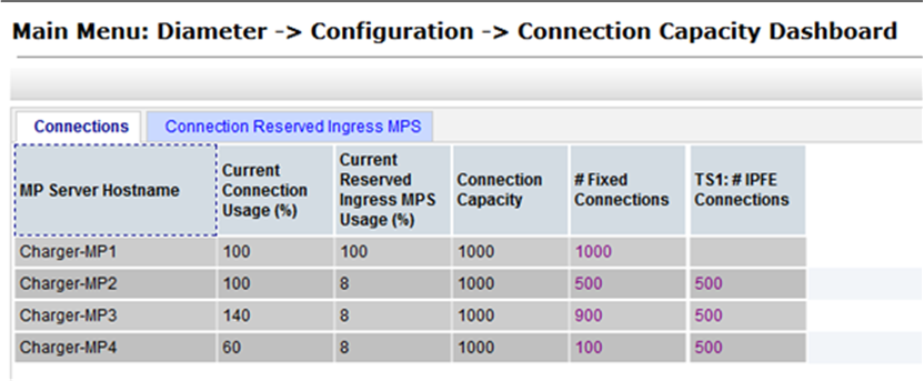
But a deeper analysis reveals that Charger-MP3 is part of just one non-overlapping Target Set, TS1. The individual DA-MP capacities within a non-overlapping Target Set can be pooled. The total available capacity of TS1 is (3 DA-MPs * 1000) = 3000 Connections. Given that there are 1500 Fixed Connections configured across the three DA-MPs, there is still room for 1500 IPFE Connections in TS1. Figure 1 shows those 1500 IPFE Connections evenly distributed across the DA-MPs, 500 each.
Taken as a whole, the TS1 DA-MPs are not over-configured. Whenever all the Connections are actually established, 500 will be established on Charger-MP2, 100 on Charger-MP3, and 900 on Charger-MP4. The Connection Capacity Validation logic correctly determined that the DA-MPs within the non-overlapping Target Set were able to accommodate all 1500 IPFE Connections configured for TS1, given the fact that each DA-MP in the Target Set has some number of Fixed Connections consuming capacity.