References
This section of the document consists of information related to intermediate
actions that needs to be performed while completing a task. The procedures
are common to all the sections and are referenced wherever required. You
can refer to the following sections based on your need.
RDBMS
RDBMS or relational
database management system stores data in the form of tables along with
the relationships of each data component. The data can be accessed or
reassembled in many different ways without having to change the table
forms.
RDBMS data
source lets you define the RDBMS engine present locally or on a remote
server using the FTP access. RDBMS can be defined to connect to any of
the RDBMS such as Oracle, Sybase, IBM DB2, MS SQL Server and any RDBMS
through native connectivity drivers or ODBC.
Passing
Runtime parameters in Data Mapping/ Data File Mapping
The following
Parameters are supported in Expressions, Joins and Filters used in the
Data Mapping definition.
$RUNID
$PHID
$EXEID
$RUNSK
$SYSDATE
$TASKID
$MISDATE
Apart from
the above $Parameters, any other parameter can be passed within Square-Brackets.
For example, [PARAM1], [PARAM2], [XYZ], [ABCD].
Additionally, L2H/H2H/T2H/H2T/F2H
mappings also support following additional default parameters. Values
for these are implicitly passed from ICC/RRF.
$MISDT_YYYY-MM-DD
- Data type is String and can be mapped to VARCHAR2. Value will be
the MISDATE in ‘yyyy-MM-dd‘ format.
$MISYEAR_YYYY
- Data type is String and can be mapped to VARCHAR2. Value will be
the year value in ‘yyyy‘ format from MISDATE.
$MISMONTH_MM
- Data type is String and can be mapped to VARCHAR2. Value will be
the month value in ‘MM‘ format from MISDATE.
$MISDAY_DD
- Data type is String and can be mapped to VARCHAR2. Value will be
the date value in ‘dd‘ format from MISDATE.
$SYSDT_YYYY-MM-DD-
Data type is String and can be mapped to VARCHAR2. Value will be the
System date in ‘yyyy-MM-dd‘ format.
$SYSHOUR_HH24
- Data type is String and can be mapped to VARCHAR2. Value will be
the hour value in ‘HH24‘ format from System date.
$MISDT_YYYYMMDD - Data type
is String and can be mapped to VARCHAR2. Value will be MISDATE in
YYYYMMDD date format.
$SYSDATE_YYYYMMDD-
Data type is String and can be mapped to VARCHAR2. Value will be system
date in YYYYMMDD date format.
Note:
The aforementioned parameters are not supported for T2T and F2T.
Two
additional parameters are also supported for L2H mappings:
[INCREMENTALLOAD] – Specify the value as TRUE/FALSE. If
set to TRUE, historically loaded data files will not be loaded
again (load history is checked against the definition name, source
name, target infodom, target table name and the file name combination).
If set to FALSE, the execution is similar to a snapshot load,
and everything from the source folder/file will be loaded irrespective
of load history.
[FOLDERNAME] – Value provided will be used to pick up the
data folder to be loaded.
For HDFS based Weblog source: Value will be suffixed to
HDFS File Path specified during the source creation.
For Local File System based Weblog source: By default the
system will look for execution date folder (MISDATE: yyyymmdd)
under STAGE/<source name>. If the user has specified the
FOLDERNAME for this source, system will ignore the MISDATE folder
and look for the directory provided as [FOLDERNAME].
Passing
values to the Runtime Parameters from the RRF module:
Values
for $Parameters are implicitly passed through RRF
Values
for dynamic parameters (given in Square Brackets) need to be passed
explicitly as: "PARAM1","param1Value", “PARAM2”,
“param2Valu
Passing values
to the Runtime Parameters from the Operations module
Value
for $MISDATE is passed implicitly from ICC
Value
for other $parameters and dynamic parameters (given in Square Brackets)
is passed as: [PARAM] = param1VALUE , $RUNSK = VALUE
Note:
If the Runtime parameter is a string or involves string comparison,
ensure that appropriate single quotes are given in the DI UI. For example,
Filter Condition can be DIM_COUNTRY.CountryName = ‘[PARAMCNTRY]’.
Back to Top
RAC
Real Application Clusters (RAC) allows multiple
computers to run RDBMS software simultaneously while accessing a single
database and providing a clustered database.
In an Oracle RAC environment, two or more
computers (each with an instance) concurrently access a single database.
This allows an application or user to connect to either of the computer
and have access to a single coordinated set of data. RAC addresses areas
such as fault tolerance, load balancing, and scalability.
Handling
Partitioned Target Tables
Data loading into a partitioned
Hive/Impala target table is supported. The partitioned columns are indicated
using a superscript P in the DI Mapping window.
You can set a static value to
a partitioned column from the AAI_FCT_PARTITION table. If it is set, you
can view it from the DI Mapping window by pointing the mouse over the
column name. You need not to map the target column to any source column.
If you map a source column to a target partitioned column which already
has a static value, the static value will get precedence.
If no static value is set to
a partitioned column, you can pass a dynamic partitioned valued. You should
map a source column to the target partitioned column. If there is no mapping
and static value is not set, the empty or blank is passed as the partition
value. Hive defaults the partition to _HIVE_DEFAULT_PARTITON_. There
is no loss of data in the non-partitioned columns.
Prescripts
Prescripts are fired on a Hive
connection, before firing a select from or insert into a hive table. While
defining Prescript, note the following:
Prescripts
should mandatorily begin with the keyword "SET".
Multiple
Prescripts should be semi-colon separated.
Prescripts
are validated for SQL Injection. The following key words are blocklisted:
"DROP","TRUNCATE","ALTER","DELETE","INSERT","UPDATE","CREATE",
"SELECT"
All validations applicable in
the UI are checked on execution also. If a prescript fails any of the
validations or if there is an error in firing the pre-script, the load
operation is exited.
Note:
For H2T, the Prescript is fired on the source.
Dynamic
Table Creation
This option allows you to create
a new table on the fly if the target Information Domain of the Data Mapping
or Data File Mapping definition is based on HDFS database. You can use
the newly created table for mapping. The newly created table will be part
of the OFSAAI data model and it is made visible and available to all other
modules.
You cannot create a table with
partition.
To dynamically create a table
From
the DI Mapping window, click  in the Target Entities pane.
The Create Table window is
displayed.
in the Target Entities pane.
The Create Table window is
displayed.
Enter
a table name and click Generate.
The new table name is displayed on the Target Entities pane.
Select
the required attributes from the Definition pane and map them to the
new Table in the Target Entities pane by clicking  button.
After
defining all mappings, click Save. The table will be created in the
HDFS/ HIVE system, with the structure/data types of the mapped columns
and it will be added to the metadata repository (both database xml
and the object registration tables). The newly created table will
be available for use in other metadata like Datasets, Hierarchies,
and so on.
Flat File Types
A Flat File is a text and binary
file which contains data in a single line, i.e. one physical record per
line. For example, a list of names, addresses, and phone numbers. Flat
Files are of two types namely, Delimated File and Fixed Width File.
Delimited File refers to a Flat
File in which the data is organized in rows and columns and are separated
by delimiters (commas). Each row has a set of data, and each column
has a type of data. For example, a csv (comma separated values) file.
Fixed Width or Fixed Position File
refers to a Flat File in which the data is defined by the character
position (tab space). The data is formulated in such a way that the
data fields are of same size and the file is compact in size. For
example, the character spacing of a Birth date data column is known
and hence the extra spaces between the Birth date column and other
column can be eliminated.
Table
Classification
DQ rules can be defined on a
table is decided by a new Servlet parameter ENABLE_CLASSIFICATION, which
is present in the web.xml file.
If ENABLE_CLASSIFICATION is set
to Y, any tables with classification code 340 can be selected as base
table for DQ rule definition. This is the old behavior.
If ENABLE_CLASSIFICATION is set
to N, then irrespective of the classification any table can be selected
as base table for DQ rule definition.
Workspace Options
The workspace option consists of the various elements available in the
user interface to help you in selecting an option or to navigate to a
specific location on the page. The available workspace options are discussed
in detail.
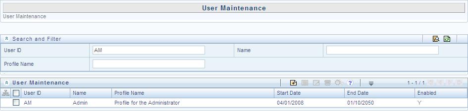
Search and Filter
The Search and Filter option in the user interface helps you to find
the required information. You can enter the nearest matching keywords
to search, and filter the results by entering information in the additional
fields.
For example, if you are in the User
Maintenance screen and need to search for administrator details,
enter the User ID and filter the
results by specifying either the Name
or Profile Description or both.
The search results are always filtered based on the additional information
you provide.
You can click  to start
a search and
to start
a search and  to reset the
search fields.
to reset the
search fields.
Back to Top
Pagination
The Pagination toolbar as indicated below is available in the user interface
screen and helps you to navigate through the display grid. The toolbar
displays the total number of available list items and the number of list
items displayed in the current view.

In the pagination toolbar, you can do the following:
Back to Top
Customize
work area
You can use the interface options to customize and auto adjusted the
work area.
To View or
Hide the left hand side (LHS) menu, click the collapsible icon.
To Expand/Collapse
a grid or section, click  or
or  icons.
Back to Top
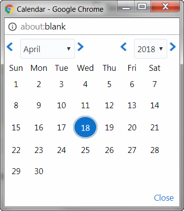
Calendar
Calendar icon in the user interface helps you to specify a date in the
DD/MM/YYYY format by selecting from the pop-up calendar. You can navigate
to the specific month or year by using the arrow buttons or select using
the drop down list. When you click on the required date the details are
auto updated in the date field.
Back to Top
Function
Mapping Codes
The following table lists the function codes with their description
to help you identify the user functions who needs to access the Infrastructure
system and map roles appropriately.
Function
Code |
Function
Name |
Function
Description |
ADAPTERS |
Run
Adapters |
The
user mapped to this function will have rights to run OFSAAI adapters |
ADDPROCESS |
Add
Process tree |
The
user mapped to this function can add the process tree |
ADDRULE |
Add
Rule |
The
user mapped to this function can add the rules |
ADDRUN |
Add
Run |
The
user mapped to this function can add the run |
ADMINSCR |
Administration
Screen |
The
user mapped to this function can access the Administration Screen |
ADVDRLTHR |
Access
to Advanced drill through |
The
User mapped to this function will have access to Advanced Drill
through |
ALDADD |
Add
Cube |
The
user mapped to this function can add cubes |
ALDATH |
Authorize
Cube |
The
user mapped to this function can authorize cubes |
ALDDEL |
Delete
Cube |
The
user mapped to this function will have rights to delete cubes |
ALDMOD |
Modify
Cube |
The
user mapped to this function can modify cubes |
ALDVIW |
View
Cube |
The user mapped to this function can
view cubes |
ALSADD |
Add
Alias |
The user mapped to this function can
add Alias |
ALSATH |
Authorize
Alias |
The user mapped to this function can
authorize Alias |
ALSDEL |
Delete
Alias |
The user mapped to this function will
have rights to delete Alias |
ALSMOD |
Modify
Alias |
The user mapped to this function can
modify Alias |
ALSVIW |
View
Alias |
The user mapped to this function can
view Alias |
APPSRVR |
Application
Server Screen |
The user mapped to this function can
access the Application Server Screen |
ATHPROCESS |
Authorize
Process Tree |
The user mapped to this function can
authorize Process Tree |
ATHRDM |
Authorize
RDM |
The user mapped to this function can
authorize RDM |
ATHRULE |
Authorize
Rule |
The user mapped to this function can
authorize the rule |
ATHRUN |
Authorize
Run |
The user mapped to this function can
authorize run |
ATTADD |
Add
Attributes |
The user mapped to this function can
add Hierarchy Attributes |
ATTATH |
Authorize
Attributes |
The user mapped to this function can
authorize Hierarchy Attributes |
ATTDEL |
Delete
Attributes |
The user mapped to this function can
delete Hierarchy Attributes |
ATTMOD |
Modify
Attributes |
The user mapped to this function can
add Hierarchy Attributes |
ATTVIW |
View
Attributes |
The user mapped to this function can
view Hierarchy Attributes |
AUD_TRL |
Audit
Trail Report Screen |
The user mapped to this function can
access the Audit Trail Report Screen |
AUTH_MAP |
Authorize
Map(s) |
The user mapped to this function can
AUTHORIZE Map definitions |
AUTH_SCR |
Metadata
Authorize Screen |
The user mapped to this function can
see Authorization Screen |
BATPRO |
Batch
Processing |
The user mapped to this function will
have rights to process batch |
BBATH |
Authorize
BBs |
The user mapped to this function can
authorize BBs |
BGCREATION |
Batch
Group Creation |
The user mapped to this function will
have rights to Creating Batch Group |
BGEXEC |
Batch
Group Execution |
The user mapped to this function will
have rights to Execute Batch Group |
BGMONITOR |
Batch
Group Monitor |
The user mapped to this function will
have rights to Monitor Batch Group Execution |
BGRESTART |
Batch
Group Restart |
The user mapped to this function will
have rights to Restart Batch Group Execution |
BPROCADD |
Add
Business Processor |
The user mapped to this function can
add business processors |
BPROCATH |
Authorize
Business Processor |
The user mapped to this function can
authorize business processors |
BPROCDEL |
Delete
Business Processor |
The user mapped to this function can
delete business processors |
BPROCMOD |
Modify
Business Processor |
The user mapped to this function can
modify business processors |
BPROCVIW |
View
Business Processor |
The user mapped to this function can
view business processors |
CFEDEF |
Cash
Flow Equation Definition |
The user mapped to this function can
view/add the
Cash Flow Equation definitions |
CFG |
Configuration |
The user mapped to this function will
have access to configuration details |
COMADD |
Add
Computed Measure |
The user mapped to this function can
add computed measures |
COMADV |
Computed
Measure Advanced |
The user mapped to this function will
have rights to the advanced options of computed measure |
COMATH |
Authorize
Computed Measure |
The user mapped to this function can
authorize computed measures |
COMDEL |
Delete
Computed Measure |
The user mapped to this function will
have rights to delete computed measures |
COMMOD |
Modify
Computed Measure |
The user mapped to this function can
modify computed measures |
COMVIW |
View
Computed Measures |
The user mapped to this function can
view computed measures |
CRTRDM |
Add
RDM |
The user mapped to this function can
Add RDM |
CRT_MAP |
Create
Map |
The user mapped to this function can
CREATE/SAVEAS Map definitions |
CWSDOCMGMT |
Document
Management Access |
The user mapped to this function can
use Document Management APIS via Callable Services Framework |
CWSEXTWSAS |
Call
Remote Web Services |
The user mapped to this function can
call web services configured in the Callable Services Framework |
CWSHIERRFR |
Refresh
Hierarchies |
The user mapped to this function can
refresh hierarchies through the Callable Services Framework |
CWSPR2ACCS |
Execute
Runs - Rules |
The user mapped to this function can
execute runs and rules through the Callable Services Framework |
CWSSMSACCS |
Remote
SMS Access |
The user mapped to this function can
access SMS APIS through the Callable
Services Framework |
CWSUMMACCS |
Remote
UMM Access |
The user mapped to this function can
access UMM APIS through the Callable
Services Framework |
CWS_STATUS |
Result
of request - Status of all |
The user mapped to this function can
access requests status through the Callable Services Framework |
CWS_TRAN |
Result
of own request only |
The user mapped to the function can
access own requests status using Callable Services Framework |
DATADD |
Add
Dataset |
The user mapped to this function can
add datasets |
DATATH |
Authorize
Dataset |
The user mapped to this function can
authorize datasets |
DATDEL |
Delete
Dataset |
The user mapped to this function will
have rights to delete datasets |
DATMOD |
Modify
Dataset |
The user mapped to this function can
modify datasets |
DATVIW |
View
Dataset |
The user mapped to this function can
view datasets |
DBATH |
Authorize
DBs |
The user mapped to this function can
authorize DBs |
DBD |
Database
Details |
The user mapped to this function will
have access to database details |
DBS |
Database
Server |
The user mapped to this function will
have access to Database Server details |
DEEADD |
Add
Derived Entities |
The user mapped to this function can
add derived entities |
DEEATH |
Authorize
Derived Entities |
The user mapped to this function can
authorize derived entities |
DEEDEL |
Delete
Derived Entities |
The user mapped to this function can
delete derived entities |
DEEMOD |
Modify
Derived Entities |
The user mapped to this function can
modify derived entities |
DEEVIW |
View
Derived Entities |
The user mapped to this function can
view derived entities |
DEFADM |
Defi
Administrator |
The user mapped to this function will
have Defi Administration rights |
DEFEXL |
DeFi
Excel |
DeFi Excel |
DEFQADM |
Defq
Administrator |
The user mapped to this function will
have Defi Administration rights |
DEFQUSR |
Defq
User |
The user mapped to this function will
have Defi user rights |
DEFUSR |
Defi
User |
The user mapped to this function will
have Defi user rights |
DELPROCESS |
Delete
Process |
The user mapped to this function can
the process |
DELRDM |
Delete
RDM |
The user mapped to this function can
delete RDM |
DELRULE |
Delete
Rule |
The user mapped to this function can
delete the rules |
DELRUN |
Delete
Run |
The user mapped to this function can
delete the run |
DEL_MAP |
Delete
Map |
The user mapped to this function can
DELETE Map definitions |
DESRDM |
Design
RDM |
The user mapped to this function can
design RDM |
DESREV |
Design
Reveleus Menu Screen |
The user mapped to this function can
access the Design Reveleus Menu Screen |
DIMADD |
Add
Dimension |
The user mapped to this function can
add dimensions |
DIMATH |
Authorize
Dimension |
The user mapped to this function can
authorize dimensions |
DIMDEL |
Delete
Dimension |
The user mapped to this function will
have rights to delete dimensions |
DIMMOD |
Modify
Dimension |
The user mapped to this function can
modify dimensions |
DIMVIW |
View
Dimension |
The user mapped to this function can
view dimensions |
DQLADD |
Data
Quality Add |
This function is for Data Quality Map
applet |
DQ_ADD |
Data
Quality Add Rule |
The user mapped to this function can
add DQ Rule |
DQ_AUTH |
Data
Quality Authorization Rule |
The user mapped to this function can
authorize DQ Rule |
DQ_CPY |
Data
Quality Copy Rule |
The user mapped to this function can
copy DQ Rule |
DQ_DEL |
Data
Quality Delete Rule |
The user mapped to this function can
delete DQ Rule |
DQ_EDT |
Data
Quality Edit Rule |
The user mapped to this function can
edit DQ Rule |
DQ_GP_ADD |
Data
Quality Add Rule Group |
The user mapped to this function can
add DQ Rule Group |
DQ_GP_CPY |
Data
Quality Copy Rule Group |
The user mapped to this function can
copy DQ Rule Group |
DQ_GP_DEL |
Data
Quality Delete Rule Group |
The user mapped to this function can
delete DQ Rule Group |
DQ_GP_EDT |
Data
Quality Edit Rule Group |
The user mapped to this function can
edit DQ Rule Group |
DQ_GP_EXEC |
Data
Quality Execute Rule Group |
The user mapped to this function can
execute DQ Rule Group |
DQ_GP_VIW |
Data
Quality View Rule Group |
The user mapped to this function can
view DQ Rule Group |
DQ_VIW |
Data
Quality View Rule |
The user mapped to this function can
view DQ Rule |
ENABLEUSR |
Enable
User Screen |
The user mapped to this function can
access the Enable User Screen |
ETLDEF |
DI
Designer |
Defining Application, Extract, Flat-File,
Mapping |
ETLDTQ |
DTDQ |
Data Quality Rules and Data Transformation |
ETLUSR |
DI
User |
The user mapped to this function will
be a Data Integrator user |
EXPMD |
Export
Metadata |
The user mapped to this function can
Export Metadata |
FIFADMIN |
Alerts
Administrator |
The user mapped to this function can
define admin mode rules |
FIFUSR |
Alerts
User |
The user mapped to this function will
be an Alerts user |
FUNCMAINT |
Function
Maintenance Screen |
The user mapped to this function can
access the Function Maintenance Screen |
FUNCROLE |
Function
Role Map Screen |
The user mapped to this function can
access the Function Role Map Screen |
FU_ATR_ADD |
Fusion
Add Attributes |
The user mapped to this function can
Create New Attributes |
FU_ATR_CPY |
Fusion
Copy Attributes |
The user mapped to this function can
Copy Attributes |
FU_ATR_DD |
Fusion
Attributes - View Dependent Data |
The user mapped to this function can
View Dependent Data for Attributes |
FU_ATR_DEL |
Fusion
Delete Attributes |
The user mapped to this function can
Delete Attributes |
FU_ATR_EDT |
Fusion
Edit Attributes |
The user mapped to this function can
Edit Attributes |
FU_ATR_HP |
Fusion
Attribute Home Page |
The user mapped to this function can
view Attribute Home Page |
FU_ATR_VIW |
Fusion
View Attributes |
The user mapped to this function can
View Attributes |
FU_EXP_ADD |
Fusion
Add Expressions |
The user mapped to this function can
Create New Expressions |
FU_EXP_CPY |
Fusion
Copy Expressions |
The user mapped to this function can
Copy Expressions |
FU_EXP_DD |
Fusion
View Dependency Expressions |
The user mapped to this function can
View Dependent Data for Expressions |
FU_EXP_DEL |
Fusion
Delete Expressions |
The user mapped to this function can
Delete Expressions |
FU_EXP_EDT |
Fusion
Edit Expressions |
The user mapped to this function can
Edit Expressions |
FU_EXP_HP |
Fusion
Expressions Home
Page |
The user mapped to this function can
view Expressions Home Page |
FU_EXP_VIW |
Fusion
View Expressions |
The user mapped to this function can
View Expressions |
FU_FIL_ADD |
Fusion
Add Filters |
The user mapped to this function can
Create New Filters |
FU_FIL_CPY |
Fusion
Copy Filters |
The user mapped to this function can
Copy Filters |
FU_FIL_DD |
Fusion
Filters - View Dependent Data |
The user mapped to this function can
View Dependent Data for Filters |
FU_FIL_DEL |
Fusion
Delete Filters |
The user mapped to this function can
Delete Filters |
FU_FIL_EDT |
Fusion
Edit Filters |
The user mapped to this function can
Edit Filters |
FU_FIL_HP |
Fusion
Filters Home Page |
The user mapped to this function can
view Filters Home Page |
FU_FIL_SQL |
Fusion
Filters - View SQL |
The user mapped to this function can
view SQL for Filters |
FU_FIL_VIW |
Fusion
View Filters |
The user mapped to this function can
View Filters |
FU_HIE_ADD |
Fusion
Add Hierarchies |
The user mapped to this function can
Create New Hierarchies |
FU_HIE_CPY |
Fusion
Copy Hierarchies |
The user mapped to this function can
Copy Hierarchies |
FU_HIE_DD |
Fusion
Hierarchies - View Dependent Data |
The user mapped to this function can
View Dependent Data for Hierarchies |
FU_HIE_DEL |
Fusion
Delete Hierarchies |
The user mapped to this function can
Delete Hierarchies |
FU_HIE_EDT |
Fusion
Edit Hierarchies |
The user mapped to this function can
Edit Hierarchies |
FU_HIE_HP |
Fusion
Hierarchy Home Page |
The user mapped to this function can
view Hierarchy Home Page |
FU_HIE_UMM |
Fusion
Hierarchies to UMM Mapping |
The user mapped to this function can
Map Fusion Hierarchies to UMM Hierarchies |
FU_HIE_VIW |
Fusion
View Hierarchies |
The user mapped to this function can
View Hierarchies |
FU_MEM_ADD |
Fusion
Add Members |
The user mapped to this function can
Create New Members |
FU_MEM_CPY |
Fusion
Copy Members |
The user mapped to this function can
Copy Members |
FU_MEM_DD |
Fusion
Members - View Dependent Data |
The user mapped to this function can
View Dependent Data for Members |
FU_MEM_DEL |
Fusion
Delete Members |
The user mapped to this function can
Delete Members |
FU_MEM_EDT |
Fusion
Edit Members |
The user mapped to this function can
Edit Members |
FU_MEM_HP |
Fusion
Member Home Page |
The user mapped to this function can
view Member Home Page |
FU_MEM_VIW |
Fusion
View Members |
The user mapped to this function can
View Members |
FU_MIG_ADD |
Object
Migration Create Migration Ruleset |
The user mapped to this function can
Create Migration Ruleset |
FU_MIG_CFG |
Object
Migration Source Configuration |
The user mapped to this function can
manipulate Source Configuration |
FU_MIG_CPY |
Object
Migration Copy Migration Ruleset |
The user mapped to this function can
Object Migration Edit Migration RulesetCopy Migration Ruleset |
FU_MIG_CRN |
Cancel
Migration Execution |
The user mapped to this function can
Cancel migration execution |
FU_MIG_DEL |
Object
Migration Delete Migration Ruleset |
The user mapped to this function can
Delete Migration Ruleset |
FU_MIG_EDT |
Object
Migration Edit Migration Ruleset |
The user mapped to this function can
Edit Migration Ruleset |
FU_MIG_HP |
Object
Migration Home Page |
The user mapped to this function can
Object Migration Link |
FU_MIG_RUN |
Execute/Run
Migration Process |
The user mapped to this function can
Run the migration process |
FU_MIG_VCF |
Object
Migration ViewSource Configuration |
The user mapped to this function can
view Source Configuration |
FU_MIG_VIW |
Object
Migration View Migration Ruleset |
The user mapped to this function can
View Migration Ruleset |
FU_SQL_ADD |
SQL
Rule Add |
This function is for SQL Rule Add |
FU_SQL_CPY |
SQL
Rule Copy |
This function is for SQL Rule Copy |
FU_SQL_DEL |
SQL
Rule Delete |
This function is for SQL Rule Delete |
FU_SQL_EDT |
SQL
Rule Edit |
This function is for SQL Rule Edit |
FU_SQL_RUN |
SQL
Rule Run |
This function is for SQL Rule Run |
FU_SQL_VIW |
SQL
Rule View |
This function is for SQL Rule View |
GMVDEF |
GMV
Definition |
The user mapped to this function can
view/add the
General Market Variable definitions |
GSTMNU |
Menu
for Guest User |
Menu for Guest User |
HCYADD |
Add
Hierarchy |
The user mapped to this function can
add hierarchies |
HCYATH |
Authorize
Hierarchy |
The user mapped to this function can
authorize hierarchies |
HCYDEL |
Delete
Hierarchy |
The user mapped to this function will
have rights to delete hierarchies |
HCYMOD |
Modify
Hierarchy |
The user mapped to this function can
modify hierarchies |
HCYVIW |
View
Hierarchy |
The user mapped to this function can
view hierarchies |
HOLMAINT |
Holiday
Maintenance Screen |
The user mapped to this function can
access the Holiday Maintenance Screen |
HSEC |
Hierarchy
Security |
The user mapped to this function will
have access to hierarchy security settings |
IBMADD |
Import
Business Model |
The user mapped to this function can
import business models |
IMPMD |
Import
Metadata |
The user mapped to this function can
Import Metadata |
IND |
Information
Domain |
The user mapped to this function will
have access to Information Domain details |
KPIATH |
Authorize
KPIs |
The user mapped to this function can
authorize KPIs |
LOCDESC |
Locale
Desc Upload
Screen |
The user mapped to this function can
access the Locale Desc Upload Screen |
MDDIFF |
Metadata
Difference Screen |
The user mapped to this function can
access the Metadata Difference Screen |
MDLAUTH |
Model
Authorize |
The user mapped to this function can
Authorize Model Maintenance |
MDLCALIB |
Model
Calibration |
The user mapped to this function can
view/add the
Model Calibration screen |
MDLCHAMP |
Model
Make Champion |
The user mapped to this function can
view the Champion Challenger screen |
MDLDEF |
Model
Definition |
The user mapped to this function can
view/add the Model definitions |
MDLDEPLOY |
Model
Deployment |
The user mapped to this function can
access the Model Deployment screen |
MDLEXEC |
Model
Execution |
The user mapped to this function can
access the Model Execution screen |
MDLOUTPUT |
Model
Outputs |
The user mapped to this function can
view the Model Outputs |
MDMP |
Metadata
Segment Map |
The user mapped to this function will
have rights to perform metadata segment mapping |
METVIW |
View
Metadata |
The user mapped to this function can
access metadata browser |
MODPROCESS |
Modify
Process Tree |
The user mapped to this function can
modify Process Tree |
MODRDM |
Modify
RDM |
The user mapped to this function can
Modify RDM |
MODRULE |
Modify
Rule |
The user mapped to this function can
modify the rules |
MODRUN |
Modify
Run |
The user mapped to this function can
modify run |
MOD_MAP |
Modify
Map |
The user mapped to this function can
SAVE Map definitions |
MSRADD |
Add
Measure |
The user mapped to this function can
add measures |
MSRATH |
Authorize
Measure |
The user mapped to this function can
authorize measures |
MSRDEL |
Delete
Measure |
The user mapped to this function will
have rights to delete measures |
MSRMOD |
Modify
Measure |
The user mapped to this function can
modify measures |
MSRVIW |
View
Measure |
The user mapped to this function can
view measures |
NVATH |
Authorize
Nested Views |
The user mapped to this function can
authorize Nested Views |
OLAPDETS |
OLAP
Details Screen |
The user mapped to this function can
access the OLAP Details Screen |
OPRADD |
Create
Batch |
The user mapped to this function will
have rights to define batches |
OPRCANCEL |
Batch
Cancellation |
The user mapped to this function can
Cancel Batch |
OPRDEL |
Delete
Batch |
The user mapped to this function will
have rights to delete batches |
OPREXEC |
Execute
Batch |
The user mapped to this function will
have rights to run, restart and rerun batches |
OPRMON |
Batch
Monitor |
The user mapped to this function will
have rights to monitor batches |
OPTDEF |
Optimizer
Add |
The user mapped to this function can
view/add the Optimizer definitions |
OPTDEL |
Optimizer
Delete |
The user mapped to this function can
delete the Optimizer definitions |
ORACBADD |
Add
Oracle Cube |
The user mapped to this function can
add Oracle cubes |
ORACBATH |
Authorize
Oracle Cube |
The user mapped to this function can
authorize Oracle cubes |
ORACBDEL |
Delete
Oracle Cube |
The user mapped to this function will
have rights to delete Oracle cubes |
ORACBMOD |
Modify
Oracle Cube |
The user mapped to this function can
modify Oracle cubes |
ORACBVIW |
View
Oracle Cube |
The user mapped to this function can
view Oracle cubes |
PGATH |
Authorize
Pages |
The user mapped to this function can
authorize Pages |
POOLDEF |
Pooling
Add |
The user mapped to this function can
view/add the Pooling definitions |
POOLDEL |
Pooling
Delete |
The user mapped to this function can
delete the Pooling definitions |
PR2SCREEN |
PR2
Screens |
The user mapped to this function can
access PR2 screens |
PROFMAINT |
Profile
Maintenance Screen |
The user mapped to this function can
access the Profile Maintenance Screen |
REPATH |
Authorize
Reports |
The user mapped to this function can
authorize Reports |
RESTPASS |
Restricted
Passwords Screen |
The user mapped to this function can
access the Restricted Passwords Screen |
RLSETCFG |
Rules
Setup Configuration Screen |
The user mapped to this function can
access the Rules Setup Configuration Screen |
ROLEMAINT |
Role
Maintenance Screen |
The user mapped to this function can
access the Role Maintenance Screen |
RULESHKDEF |
Rule
Shock Definition |
The user mapped to this function can
define the rule shocks |
SANDBXAUTH |
Sandbox
Authorize |
The user mapped to this function can
Authorize a Sandbox Maintenance |
SANDBXCR |
Sandbox
Creation |
The user mapped to this function can
view/add the
Sandbox definitions |
SANDBXMOD |
Sandbox
Maintenance |
The user mapped to this function can
view the Sandbox Maintenance |
SAVEMD |
Save
Metadata Screen |
The user mapped to this function can
access the Save Metadata Screen |
SCNDEF |
Scenario
Definition |
The user mapped to this function can
define the scenarios |
SCRBAU |
Business
Analyst User Screen |
The user mapped to this function can
access the business analyst user screen |
SCRDES |
Access
to Designer |
The User mapped to this function will
have access to Designer |
SCROPC |
Operator
Console |
The user mapped to this function will
have access to the operator console |
SCRPRT |
Portal
User |
The user mapped to this function will
be a portal user |
SCRRUN |
Access
to Runner |
The User mapped to this function will
have access to Runner |
SCRSAU |
System
Administrator Screen |
The user mapped to this function can
access system administrator screens |
SCRVIEW |
Access
to Viewer |
The User mapped to this function will
have access to Viewer |
SCR_ROR |
Access
to Operational Risk |
The user mapped to this function can
access Operational Risk |
SEGMAINT |
Segment
Maintenance Screen |
The user mapped to this function can
access the Segment Maintenance Screen |
STRESSDEF |
Stress
Definition |
The user mapped to this function can
define the stress |
SYSADM |
System
Administrator |
The user mapped to this function will
be a system administrator |
SYSATH |
System
Authorizer |
The user mapped to this function will
be a system authorizer |
TEMPATH |
Authorize
Templates |
The user mapped to this function can
authorize Templates |
TRANS_OWNR |
Access
to Transfer Ownership |
The User mapped to this function will
have access to Transfer Portal Objects |
TSK_MNU |
Access
to My Tasks |
The user mapped to this function can
access My Tasks |
UGDOMMAP |
User
Group Domain Map Screen |
The user mapped to this function can
access the User Group Domain Map Screen |
UGMAINT |
User
Group Maintenance Screen |
The user mapped to this function can
access the User Group Maintenance Screen |
UGMAP |
User
Group User Map Screen |
The user mapped to this function can
access the User Group User Map Screen |
UGROLMAP |
User
Group Role Map Screen |
The user mapped to this function can
access the User Group Role Map Screen |
USRACTREP |
User
Activity Reports Screen |
The user mapped to this function can
access the User Activity Reports Screen |
USRATH |
User
Authorization Screen |
The user mapped to this function can
access the User Authorization Screen |
USRATTUP |
User
Attribute Upload Screen |
The user mapped to this function can
access the User Attribute Upload Screen |
USRBATMAP |
User-Batch
Execution Mapping Screen |
The user mapped to this function can
access the User-Batch Execution Mapping Screen |
USRMAINT |
User
Maintenance Screen |
The user mapped to this function can
access the User Maintenance Screen |
USRPROFREP |
User
Profile Report Screen |
The user mapped to this function can
access the User Profile Report Screen |
VARDEF |
Variable
Definition |
The user mapped to this function can
view/add the Variable definitions. |
VARSHKDEF |
Variable
Shock Definition |
The user mapped to this function can
define the variable shocks |
VARTRANS |
Variable
Transformation |
The user mapped to this function can
view and add the Variable Transformation screen |
VIEWLOG |
View
log |
The user mapped to this function will
have rights to view log |
VIEWPROC |
View
Process |
The user mapped to this function can
view the process tree definitions |
VIEWRULE |
View
Rule |
The user mapped to this function can
view the rules definitions |
VIEWRUN |
View
Run |
The user mapped to this function can
view the run definitions |
VIEW_HOME |
View
OFSAAI LHS Menu |
The user mapped to this function can
view main LHS menu |
VIWATH |
Authorize
Views |
The user mapped to this function can
authorize Views |
VIWRDM |
View
RDM |
The user mapped to this function can
view RDM |
VSDEF |
VariableSet
Definition |
The user mapped to this function can
define the variablesets |
WEBSRVR |
Web
Server Screen |
The user mapped to this function can
access the Web Server Screen |
WRTPR_BAT |
Write-Protected
Batch Screen |
The user mapped to this function can
access the Write-Protected Batch Screen |
XLADMIN |
Excel
Admin |
The user mapped to this function can
define Excel Mapping |
XLUSER |
Excel
User |
The user mapped to this function can
Upload Excel Data |
Back to Top
Role Mapping
Codes
By default, the following roles are defined within the Infrastructure
application:
Role
Code |
Role
Name |
Role
Description |
CWSADMIN |
CWS
Administrator |
CWS
Administrator Role |
DEFQMAN |
DEFQ
Manager |
Data
Entry Forma and Query Manager Role |
DQADMN |
DQ
Rule Admin |
Data
Quality Rule Admin Role |
ETLADM |
ETL
Analyst |
ETL
Analyst Role |
METAAUTH |
Metadata
Authorizer |
Metadata
Authorizer Role |
ORACUB |
Oracle
Cube Administrator |
Oracle
Cube Administrator Role |
PR2ADM |
PR2
Administrator |
PR2
Administrator Role |
SYSADM |
System
Administrator |
System
Administrator Role |
SYSAMHM |
Fusion
AMHM Admin |
Fusion
Dimension Maintenance Admin Role |
SYSAMHMUMM |
Fusion
AMHM UMM Map Admin |
Fusion
UMM Maintenance Admin Role |
SYSATH |
System
Authorizer |
System
Authorizer Role |
SYSBAU |
Business
Analyst |
Business
Analyst Role |
SYSEXPN |
Fusion
Expressions Admin |
Fusion
Expressions Admin Role |
SYSFILTERS |
Fusion
Filters Admin |
Fusion
Filters Admin Role |
SYSOBJMIG |
Object
Migration Admin |
Object
Migration Maintenance Admin Role |
SYSOPC |
Data
Centre Manager |
Operator
Console Role |
SYSSQLRULE |
SQL
Rule Admin |
SQL
Rule Administrator Role |
Back to Top
Function
Role Mapping
The default roles are mapped to the following functions within the Infrastructure
application.
Roles |
Function
Mappings |
Business
Analyst |
Add Alias
Add Attributes
Add Business Processor
Add Computed Measure
Add Cube
Add Dataset
Add Derived Entities
Add Dimension
Add Hierarchy
Add Measure
Add RDM
Alias Admin
Authorize Hierarchy
Authorize Attributes
Authorize Dataset
Authorize Dimension
Authorize Measure
Business Analyst User Screen
Call Remote Web Services
Cash Flow Equation Definition
Computed Measure Advanced
Defi Administrator
Defi User
Delete Alias
Delete Attributes
Delete Business Processor
Delete Computed Measure
Delete Cube
Delete Dataset
Delete Derived Entities
Delete Dimension
Delete Hierarchy
Delete Measure
Delete RDM
Design RDM
Document management Access
Excel Admin
Excel User
Execute Runs and Rules
Export Metadata
GMV Definition
Hierarchy Attributes
Import Business Model
Import Metadata |
Model Calibration
Model Definition
Model Deployment
Model Execution
Model Make Champion
Model Outputs
Modify Alias
Modify Attributes
Modify Business Processor
Modify Computed Measure
Modify Cube
Modify Dataset
Modify Derived Entities
Modify Dimension
Modify Hierarchy
Modify Measure
Modify RDM
Optimizer Add
Optimizer Delete
Pooling Add
Pooling Delete
Refresh Hierarchies
Remote SMS Access
Result of own request only
Result of Request and Status of all
Rule Shock Definition
Sandbox Creation
Sandbox Maintenance
Scenario Definition
Stress Definition
Variable Definition
Variable Shock Definition
View Alias
View Attributes
View Business Processor
View Computed Measures
View Cube
View Dataset
View Derived Entities
View Dimension
View Hierarchy
View Measure
View Metadata
View RDM |
CWS Administrator |
Call Remote Web Services
Document Management Access
Execute Runs - Rules
Refresh Hierarchies
Remote SMS Access
Remote UMM Access
Result of own request only
Result of request - Status of all |
Data
Centre Manager |
Batch Cancellation
Batch Group Creation
Batch Group Execution
Batch Group Monitor
Batch Group Restart
Batch Monitor
Batch Processing
Create Batch
Delete Batch
Execute Batch
Operator Console
View log |
DEFQ Manager |
DeFi
Excel
Defq
User
Defq
Administrator |
DQ Rule Admin |
Data
Quality Delete Rule
Data
Quality Authorization Rule
Data
Quality Add Rule
Data
Quality Edit Rule
Data
Quality Copy Rule
Data
Quality Execute Rule Group
Data
Quality View Rule Group
Data
Quality Copy Rule Group
Data
Quality Delete Rule Group
Data
Quality Add Rule Group
Data
Quality View Rule
Data
Quality Edit Rule Group |
ETL
Analyst |
DI
Designer
DTDQ
Data
Quality Add
DI
User |
Fusion
AMHM Admin |
Fusion
Add Attributes
Fusion
Add Hierarchies
Fusion
Add Members
Fusion
Attribute Home Page
Fusion
Attributes - View Dependent Data
Fusion
Copy Attributes
Fusion
Copy Hierarchies
Fusion
Copy Members
Fusion
Delete Attributes
Fusion
Delete Hierarchies
Fusion
Delete Members
Fusion
Edit Attributes
Fusion
Edit Hierarchies
Fusion
Edit Members
Fusion
Hierarchies - View Dependent Data
Fusion
Hierarchy Home Page
Fusion
Member Home Page
Fusion
Members - View Dependent Data
Fusion
View Attributes
Fusion
View Hierarchies
Fusion
View Members |
Fusion
AMHM UMM Map Admin |
Fusion
Hierarchies to UMM Mapping |
Fusion
Expressions Admin |
Fusion
Add Expressions
Fusion
Copy Expressions
Fusion
Delete Expressions
Fusion
Edit Expressions
Fusion
Expressions Home Page
Fusion
View Dependency Expressions
Fusion
View Expressions |
Fusion
Filters Admin |
Fusion
Add Filters
Fusion
Copy Filters
Fusion
Delete Filters
Fusion
Edit Filters
Fusion
Filters - View Dependent Data
Fusion
Filters - View SQL
Fusion
Filters Home Page
Fusion
View Filters |
Infrastructure
Administrator |
Configuration
Database
Details
Database
Server
Hierarchy
Security
Information
Domain
Metadata
Segment Map
Operator
Console
Infrastructure
Administrator
Infrastructure
Administrator Screen |
Metadata
Authorizer |
Authorize
Alias
Authorize
Attributes
Authorize
BBs
Authorize
Business Processor
Authorize
Computed Measure
Authorize
Cube
Authorize
Dataset
Authorize
DBs
Authorize
Derived Entities
Authorize
Dimension
Authorize
Hierarchy
Authorize
KPIs
Authorize
Measure
Authorize
Nested Views
Authorize
Pages
Authorize
Process Tree
Authorize
RDM
Authorize
Reports
Authorize
Rule
Authorize
Run
Authorize
Templates
Authorize
Views
Metadata
Authorize Screen
Model
Authorize
Sandbox
Authorize
View
Alias
View
Attributes
View
Business Processor
View
Computed Measures
View
Cube
View
Dataset
View
Derived Entities
View
Dimension
View
Hierarchy
View
Measure
View
Process
View
RDM
View
Rule
View
Run |
Object
Migration Admin |
Cancel
Migration Execution
Execute/Run
Migration Process
Object
Migration Copy Migration Ruleset
Object
Migration Create Migration Ruleset
Object
Migration Delete Migration Ruleset
Object
Migration Edit Migration Ruleset
Object
Migration Home Page
Object
Migration Source Configuration
Object
Migration View Migration Ruleset
Object
Migration ViewSource Configuration |
Oracle
Cube Administrator |
Add
Dataset
Add
Dimension
Add
Hierarchy
Add
Measure
Add
Oracle Cube
Authorize
Oracle Cube
Business
Analyst User Screen
Delete
Oracle Cube
Modify
Dataset
Modify
Dimension
Modify
Hierarchy
Modify
Measure
Modify
Oracle Cube
View
Alias
View
Dataset
View
Dimension
View
Hierarchy
View
Measure
View
Oracle Cube |
PR2
Administrator |
Access
to Process
Access
to Rule
Access
to Run
Add
Process tree
Add
Rule
Add
Run
Delete
Process
Delete
Rule
Delete
Run
Modify
Process Tree
Modify
Rule
Modify
Run
PR2
Screens
View
Process
View
Rule
View
Run |
SQL
Rule Admin |
SQL
Rule Edit
SQL
Rule View
SQL
Rule Add
SQL
Rule Run
SQL
Rule Delete
SQL
Rule Copy |
System
Administrator |
Administration
Screen
Application
Server Screen
Audit
Trail Report Screen
Batch
Cancellation
Batch
Monitor
Configuration
Database
Details
Database
Server
Design
OFSAAI Menu Screen
Enable
User Screen
Function
Maintenance Screen
Function
Role Map Screen
Hierarchy
Security
Holiday
Maintenance Screen
Information
Domain
Locale
Desc Upload Screen
Metadata
Difference Screen
Metadata
Segment Map
OLAP
Details Screen
Operator
Console
Restricted
Passwords Screen
Role
Maintenance Screen
Rules
Setup Configuration Screen
Save
Metadata Screen
Segment
Maintenance Screen
System
Administrator
System
Administrator Screen
User
Activity Reports Screen
User
Attribute Upload Screen
User
Group Domain Map Screen
User
Group Maintenance Screen
User
Group Role Map Screen
User
Group User Map Screen
User
Maintenance Screen
User
Profile Report Screen
User-Batch
Execution Mapping Screen
View
log
Web
Server Screen
Write-Protected
Batch Screen |
System
Authorizer |
Administration
Screen
Infrastructure
Administrator Screen
Profile
Maintenance Screen
System
Administrator Screen
System
Authorizer
User
Authorization Screen
Note: To access an object, the respective
Group or Role needs to be mapped instead of functions. |
Back to Top
SMS
Auto Authorization
If auto authorization is enabled, the system authorizer needs not to
manually authorize the user- user group mapping, user group-domain mapping,
user group-role mapping and user group-role-folder mapping. The mappings
get authorized automatically.
To enable auto authorization
Execute the following query in the Configuration Schema:
UPDATE CONFIGURATION SET PARAMVALUE ='TRUE'
WHERE PARAMNAME='SMS_AUTOAUTH_REQD'
Restart the OFSAA server.
Task
Component Parameters
Components are individual functional units that are put together to
form a process. Task Component Parameters reflect the parameters that
are being applied to the selected task. Each component triggers its own
set of processes in the back-end to achieve the final output.
Click on the following components to view the tabulated view of the
parameters required for each of them:
Component:
AGGREGATE DATA
Property |
Description |
Datastore
Type |
Refers
to the type of data store such as Enterprise Data Warehouse (EDW)
which refers to the Multi-dimensional Database/Cubes. |
Datastore
Name |
Refers to the name of the Information Domain.
Click the drop down list in the Value column to select the Information
Domain.
The unique combination of the Datastore
Name and the Datastore Type determine
the physical machine on which the task will be executed. It is
assumed that the user gives the correct information else task
invocations may fail at runtime. |
IP Address |
Refers
to the IP Address of the machine on which Infrastructure Database
Components have been installed. Click the drop down list box in
the Value column to select the desired IP address. |
Cube Parameter |
Refers
to the cube identifier as defined through the Business Metadata
(Cube) menu option. Click the field in the Value column to select
the cube code. |
Operation |
Refers
to the operation to be performed. Click the drop-down list in
the Value field to select the Operation. The available options
are ALL, GENDATAFILES
and GENPRNFILES. |
Optional
parameters |
Refers
to the additional parameter that has to be processed during runtime.
You can specify the runsk value that should be processed as a
runtime parameter during execution. By default, the value is set
to "null". |
Back to Top
Component:
CREATE CUBE
Property |
Description |
Datastore
Type |
Refers
to the type of data store such as Enterprise Data Warehouse (EDW)
which refers to the Multi-dimensional Database/Cubes. |
Datastore
Name |
Refers to the name of the Information Domain.
Click the drop down list in the Value column to select the Information
Domain.
The unique combination of the Datastore
Name and the Datastore Type determine
the physical machine on which the task will be executed. It is
assumed that the user gives the correct information else task
invocations may fail at runtime. |
IP Address |
Refers
to the IP Address of the machine on which Infrastructure Database
Components have been installed. Click the drop down list box in
the Value column to select the desired IP address. |
Cube Parameter |
Refers
to the cube identifier as defined through the Business Metadata
(Cube) menu option. Click the field provided in the Value column
to select the cube code. |
Operation |
Refers
to the operation to be performed. Click the drop down list to
select the Operation.
ALL - This option will execute
BUILDDB and DLRU. BUILDDB - This option should
be used to build the outline in Essbase Cube. The outline
is built based on the parentage file(s) contents. TUNEDB - This option should
be used to analyze data and optimize cube settings. For example,
if you are trying to achieve the best block size, where 64K
bytes is the ideal size. PROCESSDB - This option
will execute BUILDDB and DLRU, and is same as All option.
Selecting this option will internally assign as ALL. DLRU - This option
should be used to Load Data in the Essbase Cube and trigger
a Rollup. ROLLUP - ROLLUP refers to
populating data in parent nodes based on calculations (E.g.
Addition). This option should be used to trigger just the
ROLLUP option where in the CALC scripts are executed. The
same is applicable for DLRU option also. VALIDATE - This option will
validate the outline. DELDB - This option will
delete the Essbase cube. OPTSTORE - This option will
create the Optimized outline for the cube. |
Back to Top
Component:
EXTRACT DATA
Property |
Description |
Datastore
Type |
Refers
to the type of data store such as Enterprise Data Warehouse (EDW)
which refers to the Multi-dimensional Database/Cubes. |
Datastore
Name |
Refers to the name of the Information Domain.
Click the drop down list in the Value column to select the Information
Domain.
The unique combination of the Datastore
Name and the Datastore Type determine
the physical machine on which the task will be executed. It is
assumed that the user gives the correct information else task
invocations may fail at runtime. |
IP Address |
Refers
to the IP Address of the machine on which Infrastructure Database
Components have been installed. Click the drop down list box in
the Value column to select the desired IP address. |
Source
Name |
Identifies
the Source from which the Extract is derived. This is defined
in the Define Source Screen of Data Integrator. Select the source
name from the drop down list. |
Extract
Name |
Identifies
the extract file definition file for the given source. This is
defined in the Define Extract screen of Data Integrator. |
Back to Top
Component:
LOAD DATA
Property |
Description |
Datastore
Type |
Refers
to the type of data store such as Enterprise Data Warehouse (EDW)
which refers to the Multi-dimensional Database/Cubes. |
Datastore
Name |
Refers to the name of the Information Domain.
Click the drop down list in the Value column to select the Information
Domain.
The unique combination of the Datastore
Name and the Datastore Type determine
the physical machine on which the task will be executed. It is
assumed that the user gives the correct information else task
invocations may fail at runtime. |
IP Address |
Refers
to the IP Address of the machine on which Infrastructure Database
Components have been installed. Click the drop down list box in
the Value column to select the desired IP address. |
Load Mode |
Refers
to the mode which user wants to work, which means the user, can
transfer data from Table to Table or File to Table. |
Source
Name |
Identifies
the Source from which the extract is derived. This is defined
in the Define Source Screen of Data Integrator. Select the source
name from drop down list. |
File Name |
Identifies
the Data File Mapping (F2T) definition name or Data Mapping (T2T)
definition name as defined for the given source. This can be different
from the data file. File Name is defined in the Data File Mapping
window (F2T) or Data Mapping (T2T) window of Data Management Tools
framework. Select the file name from the drop down list. |
Data File
Name |
The
data filename refers to the .dat file that exists in the database.
Specifying Data File Name is mandatory for F2T definition and
optional in case of T2T definition. If the file name or the .dat
file name is incorrect, the task fails during execution. |
Default
Value |
Used
to pass values to the parameters defined in Load Data Definition.
You can pass multiple runtime parameters while defining a batch
by specifying the values separated by 'comma'.
For example, $MIS_DATE=value,$RUNSKEY=value,[DLCY]=value and
so on.
Note the following:
The
parameters can either be specified with $
or within [ ]. For
example, $RUNSKEY=value or [RUNSKEY]=value. When
the definition is saved from the UI, no value is assigned
to these parameters and these are just passed for syntax correctness
only. Actual values will be passed to these parameters while
defining an ICC batch or a RUN. The
list of valid Default Parameters are:
RUNID- Data type is String and can be mapped to
VARCHAR2 PHID- Data type is String and can be mapped to VARCHAR2 EXEID- Data type is String and can be mapped to
VARCHAR2 RUNSK- Data type is Integer and can be mapped to
VARCHAR2 or INTEGER. SYSDATE- Data type is Date and can be mapped to
DATE, VARCHAR2. TASKID- Data type is String and can be mapped to
VARCHAR2 MISDATE- Data type is Date and can be mapped to
DATE, VARCHAR2.
Note:
RUNID, PHID, EXEID, RUNSK, MISDATE are implicitly passed through
RRF. Rest must be explicitly passed.
EXEC_ENV_SOURCE- This parameter is used to replace
the source of the T2T, T2H, H2T or H2H definition during
run time, provided the structure of the source in the
mapping definition is same as that of the replacing source.
Thus you can convert a T2T definition into H2T or T2H
into H2H or H2H into T2H. But the resultant definition
should not be T2T, which is not supported.
For example, [EXEC_ENV_SOURCE]=newSourceName
EXEC_ENV_TARGET- This parameter
is used to replace the target of the T2T, T2H, H2T or H2H
definition during run time, provided the structure of the
target in the mapping definition is same as that of the replacing
target. Thus you can convert a T2T definition into T2H or
H2T into H2H or H2H into H2T. But the resultant definition
should not be T2T, which is not supported.
For example, [EXEC_ENV_TARGET]=newTargetName
Note:
You can use both EXEC_ENV_SOURCE and EXEC_ENV_TARGET together
as well. Only limitation is the resultant definition should not
be T2T.
Note:
If you are converting a mapping definition to T2H using EXEC_ENV_SOURCE/EXEC_ENV_TARGET,
there is no provision in UI to specify the Split By Column/Generic
Options. In such scenarios, execution via Sqoop may fail, when
the split by column is defaulted to a string/date column.
EXECUTION_ENGINE_MODE-
This parameter is used to execute H2H on Spark. For example,
[EXECUTION_ENGINE_MODE]=SPARK CLOSE_SPARK_SESSION-
This parameter is used to close the Spark session after
executing the last H2H-Spark task in the batch.
In a batch execution, a new Spark
session is created when the first H2H-Spark task is encountered,
and the same Spark session is reused for the rest of the H2H-Spark
tasks in the same run. For the Spark session to close at the end
of the run, user needs to set the CLOSE_SPARK_SESSION to YES in
the last H2H-spark task in the batch.
For example, [CLOSE_SPARK_SESSION]=YES
Note that the
value should not contain : /*+ */. Only the content
should be given.
Note:
ALTER keyword is not supported.
Note that the value should not contain
: /*+ */. Only the content should be given.
Note:
ALTER keyword is not supported.
Apart from these, L2H/H2H/T2H/H2T/F2H data mappings also support
following additional default parameters. Values for these are
implicitly passed from ICC/RRF.
$MISDT_YYYY-MM-DD - Data type is String and can
be mapped to VARCHAR2. Value will be the MISDATE in ‘yyyy-MM-dd‘
format. $MISYEAR_YYYY - Data type is String and can be mapped
to VARCHAR2. Value will be the year value in ‘yyyy‘ format
from MISDATE. $MISMONTH_MM - Data type is String and can be mapped
to VARCHAR2. Value will be the month value in ‘MM‘ format
from MISDATE. $MISDAY_DD - Data type is String and can be mapped
to VARCHAR2. Value will be the date value in ‘dd‘ format
from MISDATE. $SYSDT_YYYY-MM-DD- Data type is String and can be
mapped to VARCHAR2. Value will be the System date in ‘yyyy-MM-dd‘
format. $SYSHOUR_HH24 - Data type is String and can be mapped
to VARCHAR2. Value will be the hour value in ‘HH24‘ format
from System date.
Note: The aforementioned parameters
are not supported for T2T and F2T.
- Only those variable which start with $ or [, will be replaced
at run time and the value of this variable will be equal to
anything starting after “=” and ending before comma “,”.
For example, if $DCCY/[DCCY] =’USD’,
$RUNSKEY=1, then the replaced value in query for $DCCY will be
‘USD’ and for $RUNSKEY will be 1.
If you are using “RUNSKEY” parameter in ICC Batch, then
ensure that you specify the value of it instead of specifying
$RUNSKEY / [RUNSKEY]. For example, FCT_STANDARD_ACCT_HEAD.N_RUN_SKEY=’$RUNSKEY’.
Since the value of RUNSKEY will not be replaced during runtime. If there are quotes specified in parameter name, then
ensure not to use quotes while defining the expression or
vice versa to avoid SQL errors. For example, if the parameter
name is $DCCY=’USD’ and the expression is defined using ‘$DCCY’
instead of $DCCY, then the final value will be ‘ ‘USD’ ’. When you execute a RUN, the run is always tagged with
a RUNSK value (a unique value for each run fired directly
from the RRF). You might have a DERIVED COLUMN in your T2T
with expression like $RUNSK. If you execute this T2T through
a RUN, a unique RUNSK value is passed implicitly to the T2T
engine, which then assigns that value wherever $RUNSK is found.
But if you try to execute the T2T through ICC, then you need
to explicitly pass a $RUNSK as a parameter so that the T2T
engine can use it.
Two additional parameters are now supported for L2H mappings:
[INCREMENTALLOAD] – Specify the value as TRUE/FALSE.
If set to TRUE, historically loaded data files will not be
loaded again (load history is checked against the definition
name, source name, target infodom, target table name and the
file name combination). If set to FALSE, the execution is
similar to a snapshot load, and everything from the source
folder/file will be loaded irrespective of load history. [FOLDERNAME] – Value provided will be used to pick up
the data folder to be loaded.
For HDFS based Weblog source: Value will be suffixed
to HDFS File Path specified during the source creation. For Local File System based Weblog source: By
default the system will look for execution date folder
(MISDATE: yyyymmdd) under STAGE/<source name>. If
the user has specified the FOLDERNAME for this source,
system will ignore the MISDATE folder and look for the
directory provided as [FOLDERNAME]. |
Back to Top
Component:
MODEL
Property |
Description |
Datastore
Type |
Refers
to the type of data store such as Enterprise Data Warehouse (EDW)
which refers to the Multi-dimensional Database/Cubes. |
Datastore
Name |
Refers to the name of the Information Domain.
Click the drop down list in the Value column to select the Information
Domain.
The unique combination of the Datastore
Name and the Datastore Type determine
the physical machine on which the task will be executed. It is
assumed that the user gives the correct information else task
invocations may fail at runtime. |
IP Address |
Refers
to the IP Address of the machine on which Infrastructure Database
Components have been installed. Click the drop down list box in
the Value column to select the desired IP address. |
Model Code |
Refers
to the model that has to be processed. This is a system generated
code that is assigned at the time of model definition. |
Operation |
The All definition for the Operation field
conveys the process of extracting the data from the flat files
and applying the run regression on the data extracted.
For Batches that are being built for the first
time the data will be extracted from the flat files and the run
regression will be applied on it. |
Optional
Parameters |
Refers to the set of parameters specific
to the model that has to be processed. This set of parameters
is automatically generated by the system at the time of definition.
You must NOT define a Model using the Define
mode under Batch Scheduling. You
must define all models using the Modeling framework menu. |
Back to Top
Component:
PROCESS_EXECUTION
This component will combine all the rules to create single or multiple
merge queries. Only rules defined on the same dataset can be merged. For
creation of queries the current order of the rules inside the process
or sub-process will be taken into consideration. Following validations
are performed to determine single or multiple DMLs for merging Rules that
is, validation on subsequent rules.
For classification-classification
or classification-computation rule combination, the target column
of the prior classification rule must not be used in any of the subsequent
rules as source hierarchies in the executable process or sub-process.
Also the same target hierarchy must not be used as a target in the
subsequent rule.
For computation-computation
rule combination, the target measures of the prior computation rule
must not be used in any of the subsequent computation rules in the
executable process or sub-process.
All the merge queries created after satisfying all the conditions will
be executed in a single transaction.
Note the following:
RRF framework
cannot validate the semantic correctness of the rules grouped for
merge. It is left to the application developer/user to make a conscious
choice.
If the merge
results in an ill-formed or runaway SQL, the framework will not be
able to detect it at design time. This is again left to application
developer/user to design the grouping that is syntactically valid.
Property |
Description |
Datastore
Type |
Refers
to the type of data store such as Enterprise Data Warehouse (EDW)
which refers to the Multi-dimensional Database/Cubes. |
Datastore
Name |
Refers to the name of the Information Domain.
Click the drop down list in the Value column to select the Information
Domain. |
IP Address |
Refers
to the IP Address of the machine on which Infrastructure Database
Components have been installed. Click the drop down list box in
the Value column to select the desired IP address. |
Process
Code |
Display
the codes of the RRF Processes defined under the selected Infodom. |
Sub Process
Code |
Display
the codes of the Sub Processes available under the selected Process. |
Build Flag |
Select
the required option from the drop down list as “Yes” or “No”.
Build Flag refers to the pre-compiled rules, which are executed
with the query stored in database. While defining a Rule, you
can make use of Build Flag to fasten the Rule execution process
by making use of existing technical metadata details wherein the
rule query is not rebuilt again during Rule execution.
Built Flag status set to “No” indicates that the query statement
is formed dynamically retrieving the technical metadata details.
If the Build Flag status is set to “Yes” then the relevant metadata
details required to form the rule query is stored in database
on “Save” of a Rule definition. When this rule is executed, database
is accessed to form the rule query based on stored metadata details,
thus ensuring performance enhancement during Rule execution. For
more information, refer Significance
of Pre-Built Flag. |
Optional
Parameters |
Refers
to the set of parameters which would behave as filter criteria
for the merge query. |
Back to Top
Component:
RULE_EXECUTION
Property |
Description |
Datastore
Type |
Refers
to the type of data store such as Enterprise Data Warehouse (EDW)
which refers to the Multi-dimensional Database/Cubes. |
Datastore
Name |
Refers to the name of the Information Domain.
Click the drop down list in the Value column to select the Information
Domain. |
IP Address |
Refers
to the IP Address of the machine on which Infrastructure Database
Components have been installed. Click the drop down list box in
the Value column to select the desired IP address. |
Rule Code |
Display
the codes of the RRF Rules defined under the selected Infodom. |
Build Flag |
Select
the required option from the drop down list as "Yes"
or "No".
Build Flag refers to the pre-compiled rules, which are executed
with the query stored in database. While defining a Rule, you
can make use of Build Flag to fasten the Rule execution process
by making use of existing technical metadata details wherein the
rule query is not rebuilt again during Rule execution.
Built Flag status set to "No"
indicates that the query statement is formed dynamically retrieving
the technical metadata details. If the Build Flag status is set
to "Yes" then
the relevant metadata details required to form the rule query
is stored in database on "Save" of a Rule definition.
When this rule is executed, database is accessed to form the rule
query based on stored metadata details, thus ensuring performance
enhancement during Rule execution. For more information, refer
Significance
of Pre-Built Flag. |
Optional
Parameters |
Refers
to the set of parameters which would behave as filter criteria
for the merge query. |
Back to Top
Component:
RUN DQ RULE
Property |
Description |
Datastore
Type |
Refers
to the type of data store such as Enterprise Data Warehouse (EDW)
which refers to the Multi-dimensional Database/Cubes. |
Datastore
Name |
Refers to the name of the Information Domain.
Click the drop down list in the Value column to select the Information
Domain.
The unique combination of the Datastore Name
and the Datastore Type determine the physical machine on which
the task will be executed. It is assumed that the user gives the
correct information else task invocations may fail at runtime. |
IP Address |
Refers
to the IP Address of the machine on which Infrastructure Database
Components have been installed. Click the drop down list box in
the Value column to select the desired IP address. |
DQ Group
Name |
Refers
to the Data Quality Groups consisting of associated Data Quality
Rule definition(s). Select the required DQ Group from the drop
down list. |
Rejection
Threshold |
Specify
the percentage of Rejection Threshold (%) limit in numeric value.
This refers to the maximum percentage of records that can be rejected
in a job. If the percentage of failed records exceeds the Rejection
Threshold, the job will fail. If the field is left blank, the
default the value is set to 100%. |
Additional
Parameters |
Specify
the Additional Parameters as filtering criteria for execution
in the pattern Key#Data type#Value; Key#Data type#Value;...etc.
Here the Data type of the value should be "V"
for Varchar/Char, or "D"
for Date with "MM/DD/YYYY" format, or "N"
for numeric data. For example, if you want to filter some specific
region codes, you can specify the Additional Parameters value
as $REGION_CODE#V#US;$CREATION_DATE#D#07/06/1983;$ACCOUNT_BAL#N#10000.50;
Note: In
case the Additional Parameters are not specified, the default
value is fetched from the corresponding table in configuration
schema for execution. |
Back to Top
Component: RUN EXECUTABLE
Property |
Description |
Datastore
Type |
Refers
to the type of data store such as Enterprise Data Warehouse (EDW)
which refers to the Multi-dimensional Database/Cubes. |
Datastore
Name |
Refers to the name of the Information Domain.
Click the drop down list in the Value column to select the Information
Domain.
The unique combination of the Datastore
Name and the Datastore Type determine
the physical machine on which the task will be executed. It is
assumed that the user gives the correct information else task
invocations may fail at runtime. |
IP Address |
Refers
to the IP Address of the machine on which Infrastructure Database
Components have been installed. Click the drop down list box in
the Value column to select the desired IP address. |
Executable |
Refers to the executable path on the DB
Server. The Executable parameter contains the executable name
as well as the parameters to the executable. These executable
parameters have to be specified as they are specified at a command
line. In other words, the Executable parameter is the exact command
line required to execute the executable file.
The path to the executable has been entered
in quotes. Quotes have to be used if the exe name has a space
included in it. In other words, the details entered here should
look exactly as you would enter it in the command window while
calling your executable. The parameter value is case-sensitive.
So, ensure that you take care of the spaces, quotes and case.
Also, commas are not allowed while defining the parameter value
for executable. |
Wait |
When the file is being executed you have
the choice to either wait till the execution is complete or proceed
with the next task. Click the drop down list to select either
Yes or No.
Clicking Yes confirms that you wish to wait for the execution
to be complete. Clicking No indicates that you wish to proceed. |
Batch Parameter |
There are four Batch Parameters in the screen:
Batch Id, BatchRun Id,
Infodate and Infodom.
Click the drop-down list to select either Yes
or No. Clicking Yes
would mean that the Batch parameters are also passed to the executable
being started. Else, the Batch parameters will not be passed to
the executable. |
Back to Top
Component:
SQLRULE
Property |
Description |
Datastore
Type |
Refers
to the type of data store such as Enterprise Data Warehouse (EDW)
which refers to the Multi-dimensional Database/Cubes. |
Datastore
Name |
Refers to the name of the Information Domain.
Click the drop down list in the Value column to select the Information
Domain.
The unique combination of the Datastore
Name and the Datastore Type determine
the physical machine on which the task will be executed. It is
assumed that the user gives the correct information else task
invocations may fail at runtime. |
IP Address |
Refers
to the IP Address of the machine on which Infrastructure Database
Components have been installed. Click the drop down list box in
the Value column to select the desired IP address. |
Folder |
Refers
to the location where the SQL Rule definition resides. Click the
drop down list box in the Value column to select the desired Folder. |
SQL Rule
Name |
Refers
to the defined SQL rule. Click the drop down list in the Value
column to select the SQL Rule. |
Back to Top
Component:
TRANSFORM DATA
Property |
Description |
Datastore
Type |
Refers
to the type of data store such as Enterprise Data Warehouse (EDW)
which refers to the Multi-dimensional Database/Cubes. |
Datastore
Name |
Refers to the name of the Information Domain.
Click the drop down list in the Value column to select the Information
Domain.
The unique combination of the Datastore
Name and the Datastore Type determine
the physical machine on which the task will be executed. It is
assumed that the user gives the correct information else task
invocations may fail at runtime. |
IP Address |
Refers
to the IP Address of the machine on which Infrastructure Database
Components have been installed. Click the drop down list box in
the Value column to select the desired IP address. |
Rule Name |
Refers
to the Data transformation name that was defined in the Post Load Transformation screen
of Data Integrator framework. Select the rule name from the drop
down list. |
Parameter
List |
Is
the list of parameters defined in Data Transformation check the
parameters must be in the same order as in the definition and
must be separated by a comma (","). Irrespective of
the data type of the parameter defined in the procedure, the parameter
specified through the front-end does not require to be specified
within quotes (' '). |
Back to Top
Component:
VARIABLE SHOCK
Property |
Description |
Datastore
Type |
Refers
to the type of data store such as Enterprise Data Warehouse (EDW)
which refers to the Multi-dimensional Database/Cubes. |
Datastore
Name |
Refers to the name of the Information Domain.
Click the drop down list in the Value column to select the Information
Domain.
The unique combination of the Datastore
Name and the Datastore Type determine
the physical machine on which the task will be executed. It is
assumed that the user gives the correct information else task
invocations may fail at runtime. |
IP Address |
Refers
to the IP Address of the machine on which Infrastructure Database
Components have been installed. Click the drop down list box in
the Value column to select the desired IP address. |
Variable
Shock Code |
Refers
to the variable shock that has to be processed. This is a system
generated code that is assigned at the time of variable shock
definition. |
Operation |
Refers
to the operation to be performed. Click the drop-down list in
the Value field to select the Operation. The available options
are ALL, GENDATAFILES
and GENPRNFILES. |
Optional
Parameters |
Refers
to Process ID and the
User ID. Click in the
text box adjacent to the Optional
Parameters field and enter the Process
ID and User ID. |
Back to Top
Component:
DIH Connector
Property |
Description |
Datastore
Type |
Refers
to the type of data store such as Enterprise Data Warehouse (EDW)
which refers to the Multi-dimensional Database/Cubes. |
Datastore
Name |
Refers to the name of the Information Domain.
Click the drop down list in the Value column to select the Information
Domain.
The unique combination of the Datastore
Name and the Datastore Type determine
the physical machine on which the task will be executed. It is
assumed that the user gives the correct information else task
invocations may fail at runtime. |
IP Address |
Refers
to the IP Address of the machine on which Infrastructure Database
Components have been installed. Click the Value
drop-down list to select the desired IP address. |
Connector |
Select
the DIH Connector you want to execute from the drop-down list.
This list displays all published connectors. |
Variables |
Enter
the required Runtime parameters for the connector.
For example, MISDATE=’10-Jan-2015’
Note the following points:
For
example: MISDATE=’10-Jan-2015’,BATCHID=22015
MISDATE=$MISDATE:dd-MM-yyyy,
BATCHID=$BATCHID
In the preceding example, the date
format appended to MISDATE has to conform to Simple Date Format.
If no date format is specified, the default date format used is
yyyymmdd.
- If variables are being used as part of connector mappings
or filter expressions, they should be passed within single
quotes as follows:
For example: MISDATE=‘$MISDATE:dd-MM-yyyy’,
BATCHID=‘$BATCHID’
- If the date format is expected in dd-MON-yyyy format, then
in Batch Task it has to be specified in the following format.
Note the difference in month format in the following example:
For example: MISDATE=‘$MISDATE:dd-MMM-yyyy’
- If parameter is used in connector filter expression for
an EDD of source type Hive, date format is expected in yyyy-MM-dd
format.
For example: MISDATE=‘$MISDATE:yyyy-MM-dd’
Note:
This is only applicable if the patch 8.0.2.1.4 (Bug - 24487929)
is applied. |
Back
to Top
Component:
Workflow Execution
Property |
Description |
Datastore
Type |
Refers
to the type of data store such as Enterprise Data Warehouse (EDW)
which refers to the Multi-dimensional Database/Cubes. |
Datastore
Name |
Refers to the name of the Information Domain.
Click the drop down list in the Value column to select the Information
Domain.
The unique combination of the Datastore
Name and the Datastore Type determine
the physical machine on which the task will be executed. It is
assumed that the user gives the correct information else task
invocations may fail at runtime. |
IP Address |
Refers
to the IP Address of the machine on which Infrastructure Database
Components have been installed. Click the drop down list box in
the Value column to select the desired IP address. |
Object
ID |
Enter
an object ID of your choice. This ID will appear as Entity ID
in the Process Monitor window. |
Workflow |
Select
the workflow you want to execute from the drop-down list. It displays
all the workflows defined in the Process Modeller window. |
Optional
Parameters |
Enter
the value you want to pass to the Dynamic Parameters of the Run
Task during the execution of the workflow. |
Back
to Top
OFSAAI Standard
XML
<BATCH BATCHNAME="Name of the Batch" NOOFTASKS="Total
no of tasks in the Batch" SYSTEMLOCALE="The locale of the system
where the batch is defined " INFODOMAIN="The Information domain
where the batch is defined" REVUSER="User who defined the batch"
DEFTYPE="To Identify whether the XML file describes a batch definition
or run (can take values 'D' in case of definition and 'R' in case of run)">
<RUNINFO REVUID="Batch Run ID"
EXTUID="External Unique ID for the Batch Run" BATCHSTATUS="Status
of the Batch Run" INFODATE="The info Date for the system"
LAG="Defines the Lag for the Batch"/>
<TASK TASKID="Task1" COMPONENTID="LOAD
DATA" TASKSTATUS="O" FILTER="H">
<PARAMETER name="IP ADDRESS"
value="A.B.C.D">
<PARAMETER name="Source Name"
value="RemoteSrc">
<PRECEDENCE>
<ONSUCCESSOF>
<TASKID></TASKID>
</ONSUCCESSOF>
<ONFAILUREOF>
<TASKID/>
</ONFAILUREOF>
</PRECEDENCE>
</TASK>
<TASK TASKID="Task2" COMPONENTID="RUN
EXECUTABLE" TASKSTATUS="O" FILTER="H">
<PARAMETER name="EXECUTABLE"
value="run.sh">
<PARAMETER name="WAIT" value="Y">
<PRECEDENCE>
<ONSUCCESSOF>
<TASKID></TASKID>
</ONSUCCESSOF>
<ONFAILUREOF>
<TASKID></TASKID>
</ONFAILUREOF>
</PRECEDENCE>
</TASK>
<TASK TASKID="Task3" COMPONENTID="EXTRACT
DATA" TASKSTATUS="O" FILTER="N">
<PARAMETER name="Source Name"
value="CardSrc">
<PARAMETER name="Extract Name"
value="Extract1">
<PRECEDENCE>
<ONSUCCESSOF>
<TASKID>TASK1</TASKID>
</ONSUCCESSOF>
<ONFAILUREOF>
<TASKID>Task2</TASKID>
</ONFAILUREOF>
</PRECEDENCE>
</TASK>
</BATCH>
The valid values for FILTER are:
Filter
Status |
Value |
H |
Hold |
R |
Released |
E |
Excluded/Skipped |
I |
Included |
Back to Top
AAI support
for R Scripts and Oracle R Enterprise (ORE) Statistical Functions
Data usage when R script is used entirely
While defining a model scripted in R, user can select Dataset and Variables
to assign data (table columns) to the R/ ORE objects used within the script.
AAI framework will prepare data from the dataset, variables and
other attributes like filters chosen for the model and will make the same
available as user specified R objects/ frames.
No specific treatment is required in the script for using the data.
User can just have an R data.frame object say ‘GDP’ and a variable (table.column)
assigned to it and use ‘GDP’ as is in the script.
Data usage
when ORE native implementation is employed - AAI Specifics to be considered
The data which is prepared from the dataset and variables as explained
in the previous section, will be available in this case as a named ORE
ore.frame object (‘OFSDATASET’) when ORE native implementations are used
(that is, when the Is ORE implementation used? checkbox is selected).
Hence, the R objects(data) must always be accessed through the ore.frame
object ‘OFSDATASET’.
For instance, if two objects say ‘x’ and ‘y’ are used and dataset/ variables
are chosen for ‘x’ and ‘y’ in the model definition, then the objects ‘x’
and ‘y’ should be accessed in the script as ‘OFSDATASET$x’ and ‘OFSDATASET$y’
respectively.
An illustration to explain the R and ORE cases is given in the following
section:-
For a simple regression model which is entirely scripted in R, that
uses a dataset and three variables (DependentVariable, IndependentVariable1
and IndependentVariable2), the user should not select the Is ORE implementation
used? checkbox. In this case the R script is as follows:
art.mod<-lm(DependentVariable ~ IndependentVariable1
+ IndependentVariable2)
art.summ<-summary(art.mod)
coef( art.summ )
art.summ[[ "r.squared" ]]
#do some line plots
new.x.datafrme = data.frame(x=seq(from=range(IndependentVariable1)[
1 ],to=range( IndependentVariable1)[2],length=length(DependentVariable)))
Here the variables chosen for the model are accessed directly in the
script as IndependentVariable1, IndependentVariable2 and DependentVariable.
Whereas for a parallel ORE implementation of the same (a dataset and
three variables DependentVariable, IndependentVariable1 and IndependentVariable2)
using ORE statistical functionalities, user must check the Is ORE implementation
used? checkbox and the script is as folllows:
art.mod<-ore.lm(DependentVariable ~ IndependentVariable1
+ IndependentVariable2, data=OFSDATASET)
art.summ<-summary(art.mod)
coef( art.summ )
art.summ[[ "r.squared" ]]
#do some line plots
new.x.orefrme = data.frame(x=seq(from=range(OFSDATASET$IndependentVariable1
)[ 1 ],to=range(OFSDATASET$IndependentVariable1)[2],length= length(OFSDATASET$DependentVariable)))
#perform some operations on the new data
Here the variables chosen for the model are accessed from OFSDATASET
as OFSDATASET$IndependentVariable1, OFSDATASET$IndependentVariable2, OFSDATASET$DependentVariable.
Back
to Top
Data Handling
It is highly recommended that data required from the database should
be pulled through the framework provided mechanism, that is, using dataset
and variables and not with any explicit DB connections. This ensures proper
security, authenticity, and auditing.
Auditing is enabled in the definition windows by introducing audit trials
that captures and displays the user details and the date of creation/
modification, along with comments.
For instance, here is a sample script where data is fetched from the
DB directly (not through framework). This way of accessing the database
resident data in a model is not recommended.
con<-dbConnect(Oracle(),"userName","password")
qry<-"select EventLoss as Y, CardType as X1, AccBalance
as X2, CustSalary as X3 from CustTable where Default= 'Y' "
res<- dbSendQuery(con, qry)
OperationalData<-fetch(res)
dbDisconnect(con)
#Model Logic
NewRegModel<-lm(Y~X1+X2+X3, data= OperationalData)
Plot(NewRegModel)
NewRegModel
Here is how a script for the same purpose can be created for accessing
data via framework dataset and variables. Define ‘EventLoss’, ‘CardType’,
‘AccBalance’ and ‘CustSalary’ from the table ‘CustTable’ as variables
in the AAI framework. While defining the model, select these variables
and assign them to R objects (the R names used within the script) say,
‘IndepVariable1’, ‘IndepVariable2’, ’IndepVariable3’ and ‘DepVar’ from
the Configure Inputs window.
#Assuming EventLoss, CardType, AccBalance, CustSalary from
#CustTable are defined as variables in a data set, and that #dataset is
selected for variable assignments to the respective R #variable names:
Y, X1, X2 and X3.
NewRegModel<-lm(DepVar ~ IndepVariable1+ IndepVariable2+
IndepVariable3)
#The variables are made directly available to the R
#environment by the framework
Plot(NewRegModel)
NewRegModel
Logging
R processing log that captures script processing information, any warnings,
errors or exceptions from the script, gets generated in the database server
at '$ORACLE_HOME/dbs', since the R executable runs completely on the database
server. Purging of the files is recommended at a regular basis.
>Back
to Top
Prediction
Techniques
Button |
Description |
Regression
Techniques |
Generalized Linear Mixed Models
with Gamma Errors
Generalized Linear Mixed Models with
Gaussian Errors
Linear Regression
Logistic Regression
Linear Regression with Mixed Effects
- ML
Linear Regression with Mixed Effects
- REML
Monte Carlo Expectation Maximization
Poisson Regression
Stepwise Regression |
Clustering |
K-means and Boundary Based Prediction
Discriminant Analysis
Hierarchical Clustering |
Classification
and Regression Trees |
GINI |
Factor
Analysis |
Principal
Component Extraction Method |
Time Series |
ARIMA |
Back to Top
Model
Parameters
The grid in the Model Details
section displays the various parameters applicable when a technique is
selected. It is mandatory to update the required information in the input
parameters and the displayed parameters vary depending on the technique
selected. Some of the common input parameter types are explained below.
Back To Top
Filter
In the Filter tab, you can add multiple non-time
hierarchy members as filters.
In
the Model Definition screen,
click  button from the Filters
toolbar. The Filter browser
is displayed.
button from the Filters
toolbar. The Filter browser
is displayed.
Select
the required filter or hierarchy from the list and click  . The selected filter is added to
the Selected Hierarchies
pane.
. The selected filter is added to
the Selected Hierarchies
pane.
Click
OK. The selected Filters are
displayed in the grid.
Filters can be applied to both Production
and Sandbox Information Domains. Select the required option Apply
in Production or Apply in Sandbox
to apply the filter in the required information domain.
Back
to Top
Inputs
For R scripted Technique:
The variables you have declared in the R script of the technique are
displayed under the Configure Script
Variables pane.
Select
a variable from the Available Variables
pane by expanding the required variable type and a variable in the
Configured Script Variables
pane, and click Map. The mapping
details are displayed in the Variable-Mapping
grid. To unmap, select the variable from the Configured
Script Variables pane and click Unmap.
Note the following:
You
cannot select a variable in the Available
Variables pane which is already mapped to another variable
in the R script.
Mapping
of single variable declared in the R script to multiple variables
is not supported if ORE implementation is used. However, for prepackaged
ORE models, multiple variable mapping to single variable in the R
script is supported.
From
the Input Parameters grid,
select the Evaluation Type
from the drop-down list. You can execute model on complete set of
records in the dataset, on a group of records or on a set of rows.
Group- Select this option if
the model needs to be executed on a group, which is defined using
a grouping variable. Select the Grouping Variable from the drop-down
list.
Row- Select this option if the
model needs to be executed on a set of rows. Specify the Number
of rows.
Note:
For Evaluation Type as Row,
graphical output (plot) is not supported and the number of records processed
is five times the value given in the Number of Rows field. These are limitations.
All
single value parameters declared in the technique are displayed. Displays
the Value if it was given
while defining the technique. Else enter the appropriate value.
Back
to Top
Include Scripts
This tab is used to source already defined algorithms to your script.
Select the required algorithms/ scripts from the Scripts
List tree and click .
You can view the scripts by selecting the
script and clicking  .
.
After adding scripts, you can position the scripts as required
by selecting it and clicking  and
and  .
.
Outputs
For R Scripted Techniques
and For Script Based Models
The Outputs
tab allows you to store the output values computed during the model execution
to a table in your atomic schema by mapping the output value to a variable,
which you have defined through the Variables Definition window. This is
supported only for record level outputs. Additionally, you can create
a new table to store the output if it is a dataframe, vector or matrix.
NOTE:
You can view the Outputs tab only after declaring Output variables (##
Output -->)in the model script.
1. From the
Outputs tab, click  corresponding to the decalred
output varibale whose value you want to map to a variable. The Variable
Browser window is displayed.
corresponding to the decalred
output varibale whose value you want to map to a variable. The Variable
Browser window is displayed.
2. Select the
appropriate variable and click Ok.
3. Select the
checkbox corresponding to Store in New
Table if you want to create a new table to store the output. New
table name is <<Outputname>>_<<ModelID>>_<<Version
Number>>. The combined length should not be more than 30. So ensure
the Output name does not have any special characters.
Note
the following limitations:
• Creating new
tables for storing the model outputs is supported only for scripted models,
executed using ORE engine.
• New table creation
may not work for Evaluation type selected as Group and Row.
Note:
For models executed using ORE engine, you can map only row level outputs
to variables.
Scenarios
Consider the following script where outputs
are not configured. Then the framework output will be just the graphical
output. The output tree will not be formed as there are no non-graphical
results. That is, when the outputs are not chosen by the user, then the
framework reports the last line’s output as the only default output.
Note that the plots are always produced.
## ---------DECLARATION------------
## Variable --> DepVar,IndepVar1,IndepVar2
## Single Value Parameter -->
## Multi Value Parameter -->
## Output -->
## --------------------------------
art.mod<-lm(DepVar ~ IndepVar1 + IndepVar2)
art.summ<-summary(art.mod)
coef( art.summ )
art.summ[[ "r.squared" ]]
#do some line plots
#plot()
#form new data.frame object
new.x.datafrme = data.frame(x=seq(from=range(IndependentVariable1)[
1 ],to=range( IndependentVariable1)[2],length=length(DependentVariable)))
#form new regression model
RegModel<-lm(DepVar ~ new.x.datafrme$x + IndepVar2)
#perform some operations on the new data
Plot(RegModel)
If you want to see the regression model components
too, you will have to configure the same by right-click selection or by
directly declaring in the Script Declaration Block. See the following
script:
## ---------DECLARATION------------
## Variable -->
## Single Value Parameter -->
## Multi Value Parameter -->
## Output --> RegModel
## --------------------------------
art.mod<-lm(DepVar ~ IndepVar1 + IndepVar2)
art.summ<-summary(art.mod)
coef( art.summ )
art.summ[[ "r.squared" ]]
#do some line plots
#plot()
#form new data.frame object
new.x.datafrme = data.frame(x=seq(from=range(IndependentVariable1)[
1 ],to=range( IndependentVariable1)[2],length=length(DependentVariable)))
#form new regression model
RegModel<-lm(DepVar ~ new.x.datafrme$x +
IndepVar2)
#perform some operations on the new data
Plot(RegModel)
In this case, the output window will have
a tree containing the components of ‘RegModel’ object with the same name
as the root node.
Alternatively, you can also put the intended
objects name at the last line of the script as:
## ---------DECLARATION------------
## Variable -->
## Single Value Parameter -->
## Multi Value Parameter -->
## Output --> RegModel
## --------------------------------
art.mod<-lm(DepVar ~ IndepVar1 + IndepVar2)
art.summ<-summary(art.mod)
coef( art.summ )
art.summ[[ "r.squared" ]]
#do some line plots
#plot()
#form new data.frame object
new.x.datafrme = data.frame(x=seq(from=range(IndependentVariable1)[
1 ],to=range( IndependentVariable1)[2],length=length(DependentVariable)))
#form new regression model
RegModel<-lm(DepVar ~ new.x.datafrme$x +
IndepVar2)
#perform some operations on the new data
Plot(RegModel)
RegModel
Here the output window will show a tree containing
the components of ‘RegModel’ object, but since the output name was not
configured or specified, it will be held under a generic framework name
‘OFSAAOutput’
One of the added advantages of configuring
the outputs is that one can get more than one object as output as shown
in the following script:
## ---------DECLARATION------------
## Variable -->
## Single Value Parameter -->
## Multi Value Parameter -->
## Output --> RegModel, art.mod
## --------------------------------
art.mod<-lm(DepVar ~ IndepVar1 + IndepVar2)
art.summ<-summary(art.mod)
coef( art.summ )
art.summ[[ "r.squared" ]]
#do some line plots
#plot()
#form new data.frame object
new.x.datafrme = data.frame(x=seq(from=range(IndependentVariable1)[
1 ],to=range( IndependentVariable1)[2],length=length(DependentVariable)))
#form new regression model
RegModel<-lm(DepVar ~ new.x.datafrme$x +
IndepVar2)
#perform some operations on the new data
Plot(RegModel)
For the above script, the output window will
contain trees for both ‘RegModel’ and ‘art.mod’.
Here are the possible scenarios and the respective
framework behavior:
The value of the last evaluated expression
is returned with the name ‘OFSAAOutput’ for the model execution.
All the objects from the script execution
environment get listed as a tree with each object as separate nodes. Now
you can choose the outputs to be reported. The selected ones will be placed
in the declaration block. If you do not select any object as output, then
the behavior will be the same as case A, for the model execution.
Now, only those which are listed in the declaration
block will come in the Configure Outputs window (as checked ones, since
you have already selected them as the outputs explicitly).
Back to Top
Transition Matrix
Transition Matrix is a statistical technique used across multiple applications
in OFSAAI. Transition Matrix is defined as a set of measures that quantify
the probability of moving data from one state to another. Transition Probability
defines the probability of transitioning data from one state to another
over the time interval. The time interval and the horizon on which probabilities
are estimated are derived from the User Input in the model definition
interface.
Transition Matrix technique parameters are completely based on historical
data. You can create multiple transition matrices and calibrated a set
of data. For example institutions may calibrate different transition matrices
for wholesale and retail exposures.
You can calibrate the parameters of a Transition Matrix technique by
defining the required options in the Model Definition screen. The Model
Definition screen within the Model Management section of OFSAAI consists
of the following five different types of transition matrix techniques.
Click on the required section to view the details.
Transition
Matrix - EWMA
In EWMA (Exponentially Weighted Moving Average) method the Decay factor
is the mandatory parameter required as user input. There is no calibration
associated with the EWMA Model. The framework predicts transition probabilities
based on user input of decay factor and time interval.
Back to Top
Transition
Matrix - Linear Regression
Linear Regression method is used to establish relationship between Explanatory
Variable(s) with a Scalar Variable. Linear Regression technique uses Linear
functions for data modeling which can also estimate the unknown model
parameters.
Regression scenario: Suppose you want to learn more about the purchasing
behavior of customers of different ages. You can build a model to predict
the ages of customers as a function of various demographic characteristics
and shopping patterns. The prediction can then be done using a regression
algorithm.
Back to Top
Transition
Matrix - Multi Factor
The Multi Factor technique of model calibration refers to the process
of estimating measures such as the Average Z-Score (difference between
Standard Deviation from Mean), Average Transition, and so on. The historical
data is transferred to the Sandbox Information Domain for model calibration.
The following are the steps required for the estimation of the above measures:
In addition to calculating realized z-scores, the calibration process
also computes the average z-score for each row of historical z-score time
series and a parameter Alpha which is the standard deviation of average
z-score shifts.
Back to Top
Transition
Matrix - Stepwise Regression
In stepwise regression, the independent variables are selected automatically
and the model is constructed in an iterative fashion. The three approaches
for achieving the stepwise regression are:
Forward
Selection: In which the inclusion of a variable completely
depends on its statistical significance.
Backward
Elimination: In which the included candidate variables are
tested for statistical significance and are eliminated as they fail.
Combination:
This includes both Forward Selection and Backward Elimination process
in which the variables are tested at different steps (check points)
to determine whether they need to be carried along or not.
Back to Top
Transition
Matrix - Time Series
Time series regression includes a series of data points considered at
consecutive time intervals. This type of analysis is done to validate
the time series data and to extract the statistics of the data under consideration.
This model can also predict the future values using the previously observed
values.
Back to Top
List
of Objects Created in Information Domain
On saving an Information Domain a list of objects will be created in
the atomic database, mapped to this Information Domain. You can view the
list in My Oracle Support Portal
by clicking on the Document ID: 1566694.1
If the required objects have not been created, there could be a problem
in connecting to the database, required privileges are not set to the
database users, or not enough space in the database. Ensure to rectify
any of the above noted issues and then save the Information Domain.
Back to Top
Authentication
and Logging
During the Oracle Financial Services Analytical Applications Infrastructure
installation you will be provided the options of selecting the authentication
type required for OFSAAI Users. You can select either SMS authentication
and authorization or the Lightweight Directory Access Protocol (LDAP)
authentication for OFSAAI login.
LDAP is a standalone access directory that provides for a logon and
requires only one user name and password, while accessing different Software.
During installation, if you have selected the LDAP Users option in the
User Configuration screen the
same will be configured for authentication.
For example, ldap://iflexop-241:389
Back to Top
Scenario
to Understand Hierarchy Security
Consider a bank "ABC" which has presence across the country
and has split their business based on regions. Each region is being managed
by a Relationship manager reporting the Chief Executive Officer. The Hierarchy
is as indicated below.
Retail
Assets Sales Head
Back to Top
Products
Personal Loans
Mortgages
Credit Cards
Auto Loans
Each product is marketed by a separate team and which is headed by a
Sales Manager who reports to the Sales Head. Each Sales Manager in turn
has two Sales Officers who are responsible for sales and profitability
of the product.
The Sales Head has decided that the Sales Officer of each product will
not have access to the information of other products. However, each Sales
Manager will have access to Sales figures of the other products.
Using the Oracle Infrastructure Security Hierarchy feature Administrator
can provide information security at hierarchy level by defining security
options for each hierarchy node. Thus, the Bank can control access of
information at a node level and not increase the overheads.
This is how it is done in Oracle Infrastructure:
First, the
Users are created in Oracle Infrastructure and then, a business hierarchy
(as defined above) is created.
Now, the bank
can restrict access of certain information to certain people in the
Hierarchy Security configuration. In this screen,
The administrator
can control the security by mapping the users to various nodes in
the hierarchy.
For example, the administrator maps Sales
Officer 1 and Sales Officer 2 to only the Personal Loans Node in the Product
hierarchy. This restricts Sales Officer 1 and 2 to only viewing and maintaining
their particular node in the hierarchy.
By default, all the users mapped to a domain
can access all the hierarchy levels to which they are mapped. This function
allows the administrator to restrict or exclude a user/s from accessing
restricted nodes.
Back
to Top
Create
Tree View Form
The process to create a Form using the Tree
View Layout differs from the procedure as explained for other layouts.
You can create a Form using the Tree View Layout, by selecting either
Dimensional Table Tree or Parent Child Tree.
Dimensional
Table Tree
If you want to create a Form using the Dimension
table Tree, select Tree view > Dimension
Table Tree option in the DEFQ
- Layout screen. On clicking Next,
you need to provide the required details in the following screens:
Dimension Table Selection: Enter
the Root Name and select the
Table. Click Next.
Fields Selection: Select required
Fields to Display from Available fields and click Next.
Dimension Node Selection: Select
Field Nodes from Available fields
and click Next.
Select
Dimensional Tree Nodes for the selected fields and click Next.
DEFQ Field Properties screen: Specify
the required details. For more information, refer DEFQ
Field Properties.
Back
to Top
Parent Child
Tree
If you want to create a Form using the Parent
Child Tree, select Tree view > Parent
Child Tree option in the DEFQ
- Layout screen. On clicking Next,
you need to provide the required details in the following screens:
Hierarchy Table Selection: Enter
the Root Name and select the
Table. Click Next.
Parent-Child Node Selection: Select
Parent Node, Child Node, and Node Description from the drop down list.
Fields Selection: Select required
Fields to Display from Available fields and click Next.
DEFQ Field Properties screen: Specify
the required details. For more information, refer DEFQ
Field Properties.
Back
to Top
Applying Rules
You can apply rules to Validate Form Data
to specific fields such as Text Field, Text Area, or Protected Field.
To specify rules for a field in the DEFQ - Forms Designer DEFQ
Field Properties screen:
Click
Rule adjacent to the required
field. The Specifying Rules and
Expressions for Data Validations screen is displayed.
Select
the required Fields, Operators, and Functions from the list.
Enter
the Rule Expression in the Expression Viewer field.
Depending
on the data type of the selected field, the following column constraints
are displayed. Select the required check box.
No
Spaces
Characters
Only
Alpha
Numeric
Not
Null
Non
Negative
Select
the Alignment type from the
drop down list.
Click
OK and save the details.
Back
to Top
Define
List of Values
While creating a Form, if you choose the Select List field parameter option
in the In Edit/Add column in
the DEFQ Field Properties screen,
you need to define the list of values in the Select
List Screen. However, you do not need to define the values for
foreign key fields and primary key fields.
In the Select
List Screen, select the required Field Type from the following
options:
Comma Separated Values: Supports
only the user specified values while creating a Form.
Dynamic List of Values: Supports
fieldname from a table and stores it in the database. The same can
be used during Data Entry.
If Comma
Separated Values is selected:
Enter
the List of Values to be displayed.
Specify
Alternate Display Values to
be displayed.
Click
OK and save the specified
list of values.
If Dynamic
List of Values is selected:
Select
Table Value, List Value, and Display Value field.
Select
the Field, Operator, and Functions from the list.
Define
a filter condition for the selected values.
Click
OK and save the specified
list of values.
Back
to Top
Define
Messaging Details
While creating a Form, you can click Message Details in the DEFQ
Field Properties screen to define the messaging details. You can
specify an alert message which is sent to the Creator of the Form or to
an Authorizer.
In the Messaging
Details for a Form screen:
Select
Messaging Required checkbox
to activate the Messenger feature.
Note:
If the option is not selected, a single mail is sent for the entire batch.
Message details such as recipients, subject, and contents are fetched
from the metadata.
Select
the required Available Message Types
from the list and click
button.
Select
the Message Type from the
drop-down list based on specific action.
Select
Specific Messages Required
to add a specific message.
Select
Available Fields for Subject,
Content, & Recipients
from the list and click
button.
Click
Save and save the messaging
details. You also need to select Save
with Authorization in the DEFQ
Field Properties screen for the messages to be functional.
Back
to Top
Form Data
Versioning
You can perform data versioning on an authorized
Form. The modifications made to the particular Form is tracked and displayed
as per date versioning. In the Data
Versioning for Form screen, do the following:
Select
Enable Data Versioning checkbox
to ensure that the version is tracked.
Select
the Table and Version
Identifier from the drop down list.
Click
OK and save the versioning
details.
Back
to Top
Flat File
Flat files are data files that store records
with no structured relationships. You can define the data source of a
flat file present locally or on a remote server.
Flat-File present in local data source resides
in the staging area of the Infrastructure Database Server. Additional
metadata information such as file format properties is required to interpret
these files. Flat-File present on a remote server can be accessed through
FTP connection to load the remote data-file into the Staging area of the
Infrastructure Database Server.
The Data Source for a Flat-File serves the
purpose of logically grouping a set of Flat-Files getting loaded into
the Warehouse from a defined source application.
Back to Top
Save With Authorization
The Save with Authorization feature in Forms
Designer (Sort Fields Selection screen) allows you to authorize the uploaded
data. Authorization serves as a checkpoint for validation of uploaded
data.
To authorize the uploaded data, you need to
create a Form in DEFQ with the Save with
Authorization checkbox selected.
Before
any DEFQ Form is created to authorize the data, the underlying table
in the data model needs to have below columns added to its table structure.
You need to perform a data model upload to have the new structures
reflected in the application.
Columns required:
V_MAKER_ID VARCHAR2(20),
V_CHECKER_ID VARCHAR2(20),
D_MAKER_DATE DATE,
D_CHECKER_DATE DATE,
F_AUTHFLAG VARCHAR2(1),
V_MAKER_REMARKS VARCHAR2(1000),
V_CHECKER_REMARKS VARCHAR2(1000)
Navigate
to Create a New Form in the Forms Designer section and complete the
design steps up to Step 6. From the DEFQ Field Properties screen,
select the appropriate values as listed below for Store
Field As depending on the columns selected:
V_MAKER_ID - MakerID
V_CHECKER_ID - CheckerID
D_MAKER_DATE - Maker Date
D_CHECKER_DATE - Checker Date
F_AUTHFLAG - AuthFlag
V_MAKER_REMARKS - Maker Remarks
V_CHECKER_REMARKS - Checker Remarks
Click
Save with Authorization. Once
data is loaded into the table, you can login as 'Authorizer' and navigate
to the Data Entry screen.
Select the Form to open and authorize the records loaded.
Back
to Top
Define Expression
You can define
an expression in the Specify
Expression screen to join two
selected tables. Click  button.
The Specify Expression
window is displayed.
button.
The Specify Expression
window is displayed.
The Specify
Expression window consists of
the following sections:
Entities - consists of the Entities
folder with the list of tables that you selected from the Entity Groups
folder. Double-click the Entities folder to view the selected dimension
tables (Product and Segment tables).
Functions - This
is divided as Database Functions and User Defined Functions.
Database Functions consists of functions that are specific to databases
like Oracle and MS SQL Server. You can use these functions along with
Operators to specify the join condition. The Functions categories
are displayed based on the database types as tabulated.
Database |
Functions |
Transact
SQL |
Specific to MS SQL
server which consists of Date & Time, Math and System functions. |
SQL
OLAP |
Specific to Microsoft
OLAP which consists of Array, Dimension, Hierarchy, Logical, Member,
Number, Set, and String functions. |
SQL |
Specific
to Oracle which consists of String, Aggregate, Date and Time,
and Mathematical functions. |
Note:
It is not mandatory to specify a Function for a join condition.
Operator |
Types |
Arithmetic |
+, -, %, * and / |
Comparison |
'=', '!=', '< >',
'>', '<', >=, <=,'IN', 'NOT IN', 'ANY', 'BETWEEN',
'LIKE', 'IS NULL', and 'IS NOT NULL'. |
Logical |
'NOT', 'AND' and 'OR' |
Set |
UNION, UNION ALL, INTERSECT
and MINUS |
Others |
The Other operators
are 'PRIOR', '(+)', '(' and ')'. |
Concatenation |
|| |
To specify
the join condition:
Select
the Entity of the fact table
to which you want join the dimension entities.
Select
a Function depending on the
database type.
Select
the Operator which you want
to use for the join condition.
Select
the second Entity from the Entities pane that you want to join with
the first entity. You can also select more than one dimension table
and link to the fact table.
The defined
expression is displayed in the Expression section. You can click button to reset the values or click  button to erase the specific value.
Click
OK. The defined expression
is validated as per the selected table and entity definition and on
successful validation, is displayed in the main screen.
Back
to Top
Search Hierarchies
To search for a particular member:
Enter
the keyword and click GO.
If
a result containing the keyword is located, the corresponding member
is highlighted.
Click
Search again and the next
member that contains the keyword is highlighted.
Back
to Top
Hierarchical
Member Selection Modes
To aid the selection process, certain standard
modes are offered through a drop-down. The available modes are Self,
Self & Descendants, Self & Children, Parent,
Siblings, Children,
Descendants, and Last
Descendants.
Based on the hierarchy member security applied,
the nodes/members of the hierarchy are displayed in enabled or disabled
mode. The members which are in enabled mode only can be selected. That
is, the members which are mapped to your user group only can be selected.
For example, if you choose Self & Children, the immediate children
of the selected hierarchy, which are mapped to your user group only will
be moved to the RHS pane.
The
Self mode is the default mode
displayed. In this mode, only the specific member selected in the
LHS pane will be selected onto the RHS pane.
Choose
the Self & Descendent
mode when you want a specific member and all its descendants right
up to the end of its branch to be selected onto the RHS pane.
Choose
the Self & Children mode
when you want a specific member and only its immediate children to
be selected onto the RHS pane.
Choose
the Parent mode when you want
to select only the parent member of a selected member onto the RHS
pane.
Choose
the Siblings mode when you
want to select only the sibling members from the same parent of the
selected member onto the RHS pane.
Choose
the Children mode when you
want only the immediate children of a specific member to be selected
onto the RHS pane mode.
Choose
the Descendants mode when
you want to select only the descendant members of selected member
onto the RHS pane.
Choose
the Last Descendants mode
when you want to select only the last descendant members of selected
member onto the RHS pane.
You can also click  to select all the members to the Selected
Members pane. Click
to select all the members to the Selected
Members pane. Click  to
deselect a selected member from the Selected
Members pane or click
to
deselect a selected member from the Selected
Members pane or click  to deselect all the
members.
to deselect all the
members.
Back
to Top
Default Member
To mark an item as a default member:
Select
a member in the Selected Members pane.
Select
Mark as Default checkbox and
the Default Member field is displayed with the selected member name.
If more than one item is selected the Mark
as Default option is disabled. The item marked as default is automatically
mapped to the non-leaf member combinations of hierarchies selected as
source. At the least one member must be marked as the default member to
save the rule definition.
To change the default member:
Select
the current default member.
Deselect
the Mark as Default checkbox.
Select
a new hierarchy member and mark as default.
Back
to Top
Tools Menu
This section comprises of the common tool
menu buttons present in the Rules, Processes, and Run sections of the
Rules Framework component in the Infrastructure system. The Rules menu,
Process menu, and Run menu have the following buttons in common.
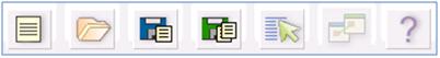
New
Click  button
to add a new Rule, Process, or Run definition.
button
to add a new Rule, Process, or Run definition.
In order to proceed with creating a new Rule
definition you must select the source dataset type from the Source Dataset
drop down menu on the top of the Designer
screen. The Process definition can be a baseline definition or a variation
of the baseline definition (scenario definition). The Run definition may
be a baseline definition or a variation of the baseline definition termed
as simulation run.
If you are working on a new definition and
subsequently move to the New/Open menu option without saving the new definition,
the system displays an alert that requests for your confirmation.
Back to
Top
Open
Click
 button to open an existing
Rule, Process, or Run definition. The list of Information Domains
mapped are displayed in the Open
dialog.
button to open an existing
Rule, Process, or Run definition. The list of Information Domains
mapped are displayed in the Open
dialog.
Select
the Information Domain to
view the list of available Segments mapped to the selected Information
Domain.
Double-click
to select the Segment within
the pop-up menu to view either the list of associated definitions
or the list of definitions.
Select
the definition from the list and click Open.
If you open a Process or Run definition,
you are prompted to select the Process
Type or Run Type.
Back to
Top
Save
Click
 button to save a new
definition or a modified definition.
button to save a new
definition or a modified definition.
The Save
dialog is displayed with the existing definitions available in the selected
Information Domain.
Enter
the Name for the new definition in the Name
text box provided.
Click
Save to save the definition
in the selected Information Domain and Segment. A confirmation message
is displayed if the operation is successful.
A source to target mapping must be defined
to save a Rule definition and at least one rule must be defined as a sub-process
member to save a Process definition.
Back to
Top
Save As
Click
 button and the Save As dialog is displayed.
Enter
a Name for the definition in the Name
field.
Click
Save to save the definition
in the selected Information Domain and Segment. A confirmation message
is displayed if the operation is successful.
Back to
Top
Properties
Click
 button and the Properties Dialog is displayed.
The Properties
Dialog displays the metadata such as Created By, Created Date,
Modified By, Modified Date, Authorized By, and Authorized Date in the
Property (default) tab.
Click
Comments tab in the Properties Dialog and enter the
narration/comments about the created definition.
If
you are working on a Rule definition or a Run Definition:
Select
Display Description checkbox
if you want the description of the hierarchies to be displayed
in the work area.
Select
Indent Hierarchy checkbox
if you want to view the hierarchies in tree structure.
Select
the Process Type as End to End
or Non-End to End in case
you are working on a Process definition.
Click
OK and save the definition
with the changes.
Back to
Top
Map
Map button is enabled only in the Rules Framework
Designer screen for Scenario
Process definition.
Click
 button from the tools
menu.
button from the tools
menu.
The Base
Process Selector dialog is displayed with the list of mapped End
to End processes.
In
the Base Process Selector
dialog:
Click
ADD to select the End
to End Base process under the selected Information Domain and
Segment from the End to End
Base Processes dialog.
Click
DELETE to remove a selected
mapped End to End process from the list.
Click
OK to map the selected End
to End Base process from the list.
Back to
Top
Process
Hierarchy Members
The Process Hierarchy Members and their description
are as tabulated.
Component |
Description |
Data Extraction
Rules |
Display
all the Extract definitions defined through OFSAAI Data Integrator. |
Load Data
Rules |
Display
the following two sub types of definitions:
File Loading Rules display
the entire File to Table definitions defined through OFSAAI
Data Integrator. Insertion Rules (Type1 Rules)
display all the Table to Table definitions defined through
OFSAAI Data Integrator. |
Transformation
Rules |
Display
the following definition sub type:
|
Base Rules |
Display
the following two sub types of definitions for both PR2 and RRF:
In case of PR2:
In case of RRF:
Classification Rules (type
2 rule) display all the type 2 rules defined in the Rules
framework which have Active status as "Yes"
and Version "0". Computation Rules (type
3 rule) display all the type 3 rules defined in the Rules
framework which have Active status as "Yes"
and Version "0". |
Processes |
In
case of PR2, Process displays
all the existing Non End-to-End processes defined through Process
Designer.
In case of RRF, Process
displays all the existing processes defined through Process Framework
which have Active status as "Yes"
and Version "0". |
Essbase
Cubes |
Displays
all the Essbase cubes defined for the selected Information Domain
in OFSAAI unified metadata manager.
Note: The cubes under
the segment to which the user is mapped only will be displayed. |
Oracle
Cubes |
Displays all the Oracle cubes defined for
the selected Information Domain.
Note:
The cubes under the segment to which the user is mapped only will
be displayed. |
Model |
Displays
all the existing model definitions defined in the Modeling framework
screens. |
Stress
Testing |
Displays
all the existing stress testing definitions defined in the Variable
Shock Library, Scenario Management, and Stress Definition screens. |
Data
Quality |
Displays all data quality groups defined
from the OFSAAI Data quality Framework.
The DQ Rule framework has been
registered with RRF. While passing additional parameters during
RRF execution, the additional parameters are passed differently
(when compared to DQGroup execution). For example, if the additional
parameters to be passed are : $REGION_CODE#V#US;$CREATION_DATE#D#07/06/1983;$ACCOUNT_BAL#N#10000.50,
then they are passed as: "REGION_CODE","V","US","CREATION_DATE","D","07/06/1983",
"ACCOUNT_BAL","N","100 00.50". In
case the user wants to input threshold percentage (for example,:
50%), then the parameter string passed is as follows: "50","REGION_CODE","V","US","CREATION_DATE","D","07/06/1983","ACCOUNT_BAL","N",
"10000.50". In the absence of the threshold parameter,
it is assumed to be 100%, by default. |
The parameters needed to execute all the listed
components are explained in References
> Seeded
Component Parameters section.
Back
to Top
Scenario
to understand Data set Functionality
Consider the scenario, where you want to analyze
the Customer Relationship Management through various profiles of a customer
against the various transactions and the channels of transaction through
which the actual transactions have happened.
This information is maintained in relational
tables. In a typical Star Schema implementation of the relations, Customer
profiles like Age, Gender, Sex, Residence, and Region are maintained in
Individual Dimension tables. Similarly, the Transaction Types and Channels
would be maintained in a separate Dimension tables. The actual transaction
performed by the Customers will be stored in a Fact table.
A Data Set allows you to collate all the tables
with a valid join condition. The tables defined in the data set would
form the FROM clause while aggregating for the Cube.
Back
to Top
List Unauthorized
When you are searching for a derived entity
code, you can select the List Unauthorized
checkbox in the search dialog to view all the unauthorized Derived Entity
definitions.
The unauthorized list displays the modified
Derived Entities, and the Derived Entity which are to be authorized. Users
having Authorize rights will only be able to view the list of unauthorized
Derived Entity definitions.
Back
to Top
Create Expression
You can define an expression in the Expression screen to join two selected
tables. Click  button. The Expression screen is displayed.
The Expression
screen consists of the following sections:
Entities - consists of the Entities
folder with the list of tables that you selected from the Entity Groups
folder. Double-click the Entities folder to view the selected dimension
tables (Product and Segment tables).
Functions - consists of functions
that are specific to databases like Oracle and MS SQL Server. You
can use these functions along with Operators to specify the join condition.
The Functions categories are displayed based on the database types
as tabulated.
Database |
Functions |
Transact
SQL |
Specific
to MS SQL server which consists of Date & Time, Math and System
functions. |
SQL OLAP |
Specific
to Microsoft OLAP which consists of Array, Dimension, Hierarchy,
Logical, Member, Number, Set, and String functions. |
SQL |
Specific
to Oracle which consists of Character, Conversion, Date and Numeric
functions. |
Note:
It is not mandatory to specify a Function for a join condition.
Operator |
Types |
Arithmetic |
+,
-, %, * and / |
Comparison |
'=',
'!=', '< >', '>', '<', 'IN', 'NOT IN, 'ANY', 'SOME',
'LIKE' and 'ALL'. |
Logical |
'NOT',
'AND' and 'OR' |
Set |
UNION,
UNION ALL, INTERSECT and MINUS |
Others |
The
Other operators are 'PRIOR', '(+)', '(' and ')'. |
To specify the join condition:
Select
the Entity of the fact table
to which you want join the dimension entities.
Select
a Function depending on the
database type.
Select
the Operator which you want
to use for the join condition.
Select
the second Entity from the Entities pane that you want to join with
the first entity. You can also select more than one dimension table
and link to the fact table.
Click
OK and save the join condition
details.
Back
to Top
Base
and Computed Measures
A Base Measure
refers to a measure where the aggregation is done directly on the raw
data from the database. It represents some operation on the actual data
available in the warehouse and its storage in its aggregated form in another
data store. This is different from metrics that is not stored in physical
form, but as functions that can be operated on other measures at viewing
time. The choice of base or computed measure is based on the user requirement
of a design issue on storage optimality as it is on query response speeds
desired. These functions defined on other measures are called Computed
Measures and dealt separately. It is the metric definition like
amount of sales or count of customers.
Back
to Top
Define
Business Hierarchy Types
The available Business Hierarchies are as
tabulated.
Hierarchy
Type |
Description
/ Hierarchy Sub Type |
Regular |
In
a Regular Hierarchy Type, you can define the following Hierarchy
Sub Types:
In a non Business Intelligence Enabled
Hierarchy, you need to manually add the required levels. The levels
defined will form the Hierarchy.
You can Enable Business Intelligence
hierarchy when you are not sure of the Hierarchy structure leaf
values or the information is volatile and also when the Hierarchy
structure can be directly selected from RDBMS columns. The system
will automatically detect the values based on the actual data.
This option can be selected to define
a Parent Child Type hierarchy. |
Measure |
A
Measure Hierarchy consists of the defined measure as nodes and
has only the Non Business Intelligence
Enabled as Hierarchy Sub Type. |
Time |
A
Time Hierarchy consists of the levels/nodes of high time granularity
and has only the Business Intelligence
Enabled as Hierarchy Sub Type. |
You can select the required Business Hierarchy
from the drop down list and specify the Hierarchy Sub Type details. The
screen options differ on selecting each particular Hierarchy type. Click
on the following links to view the section in detail.
Define
Regular Hierarchy
When you select Regular Hierarchy, you can
define the Hierarchy Sub Type for Non Business Intelligence Enabled, Business
Intelligence Enabled, and Parent Child Hierarchy. Select the required
Hierarchy Sub Type from the drop down list. Click on the following links
to view the section in detail.
Define
Non Business Intelligence Enabled Hierarchy
When you have selected Regular
- Non Business Intelligence Enabled Hierarchy option, do the following:
Click
button in the Entity field. The
Entity and Attribute screen is displayed.
You
can either search for a specific Entity
using the Search
field or select the checkbox adjacent to the required Entity
in the Available Entities
list. The list of defined Attributes
for the selected entity is displayed Available
Attributes list.
You
can either search for a specific Attribute using the Search field or select
the checkbox adjacent to the required Attribute
in the Available Attributes
list.
Click
Save. The selected Entity and Attribute
is displayed in the Add Business
Hierarchy screen.
Note:
Ensure that the values present in Attribute column do not contain new
line characters. Because the hierarchy node descriptions in the hierarchy
browser are considered as text fields and do not permit new line characters.
Click button from
the Business Hierarchy tool bar. The Add
Node Values screen is displayed.
Field |
Description |
Node |
The
Node value is auto-populated and is editable. |
Short Description |
Enter
the required short description for the node. |
Node Identifier |
Click
button and define
an expression in the Expression
screen for the Node Identifier. For more information, refer Create
Expression. |
Sort Order |
Enter
the Sort order in numeric value.
Note: The sort order
of the default (OTHERS) node should be greater than the rest of
the nodes if this hierarchy is used in RRF Filter condition. |
There are four Storage
Types as tabulated.
Field |
Description |
Data Store |
This
storage type allocates a data cell for the information to be stored
in the database. The consolidated value of the data is stored
in this cell. The consolidation for the node occurs during the
normal process of rollup. |
Dynamic
Calc |
In
this storage type, no cell is allocated and the consolidation
is done when the data is viewed. The consolidation for the node
is ignored during the normal process of rollup. The consolidation
of node occurs when you use the OLAP tool for viewing data. |
Dynamic
Calc & Store |
In
this storage type, a cell is allocated but the data is stored
only when the data is consolidated when viewed, for the first
time. The consolidation for the node is ignored during the normal
process of rollup. It occurs only when you first retrieve the
data from the database. |
Label |
In
this storage type, a cell is not allocated nor is the data consolidated.
It is only viewed.
Note: The Label storage
type is specific to Essbase MOLAP. Storage type is applicable
only for the Regular hierarchy type and Measure. If the user wants
to specify a dynamic calc option at level members in a multi-level
time hierarchy, the same is provided through OLAP execution utility. |
Click
Save in the Add
Business Hierarchy screen and save the details.
In the Business Hierarchy tool bar, you can
also do the following:
Field |
Description |
Add Hierarchy
Node |
Click
button adjacent to
Child of field and select
the required Member in the Hierarchy
Browser screen. Click OK. |
Consolidation
Type |
Consolidation
Type option is available to Essbase MOLAP. There are six consolidation
types such as Addition, Subtraction, Product, Division, Percent,
and Ignore. Select the required option from the drop down list. |
Back
to Top
Define
Business Intelligence Enabled Hierarchy
When you have selected Regular
- Business Intelligence Enabled Hierarchy option, do the following:
(Optional)
Select Total Required checkbox,
if you want the total of all the nodes.
(Optional)
Select List checkbox to retrieve
information from database when queried.
Note:
List hierarchy can have only one level and you cannot select List option
if the Total Required option has been selected. Refer List
hierarchy.
Click
button in the Entity
field. The Entity and Attribute
screen is displayed.
You
can either search for a specific Entity
using the Search
field or select the checkbox adjacent to the required Entity
in the Available Entities
list. The list of defined Attributes
for the selected entity is displayed Available
Attributes list.
You
can either search for a specific Attribute
using the Search
field or select the checkbox adjacent to the required Attribute
in the Available Attributes
list.
Click
Save. The selected Entity
and Attribute is displayed in the Add
Business Hierarchy screen.
Note:
Ensure that the values present in Attribute column do not contain new
line characters. Because the hierarchy node descriptions in the hierarchy
browser are considered as text fields and do not permit new line characters.
Click
button from the Business Hierarchy
tool bar. The Add Hierarchy levels
screen is displayed.
Field |
Description |
Level |
The
Level value is auto-populated and is editable. |
Short Description |
Enter
the required short description for the level. |
Level Identifier |
Click
button and define
an expression in the Expression
screen for the Level Identifier. For more information, refer Create
Expression. |
Level Description |
Click
button and define
an expression in the Expression
screen for the Level Description. For more information, refer
Create
Expression. |
Note:
BI Hierarchy value refresh on On Load property
is not functional for data loads performed through Excel Upload. It is
applicable only for data loads which run through a batch process.
Click
Save in the Add
Business Hierarchy screen and save the details.
In the Business Hierarchy tool bar, you can
also do the following:
Click
button to Add subsequent Levels.
For the second or subsequent levels, the levels are incremented.
Click
 button by selecting the required
level checkbox to edit the Level details.
button by selecting the required
level checkbox to edit the Level details.
Click
 button to delete the defined Level details.
Back
to Top
Define
Parent Child Hierarchy
When you have selected Regular
- Parent Child Hierarchy option, do the following:
Click
button in the Entity
field. The Entity and Attribute
screen is displayed.
You
can either search for a specific Entity
using the Search
field or select the checkbox adjacent to the required Entity
in the Available Entities
list. The list of defined Attributes
for the selected entity is displayed Available
Attributes list.
You
can either search for a specific Attribute using the Search field or select
the checkbox adjacent to the required Attribute
in the Available Attributes
list.
Click
Save. The selected Entity
and Attribute is displayed in the Add
Business Hierarchy screen.
Note:
Ensure that the values present in Attribute column do not contain new
line characters. Because the hierarchy node descriptions in the hierarchy
browser are considered as text fields and do not permit new line characters.
The
Business Hierarchy section displays the pre-defined nodes such as
Child code, Parent Code, Description, Storage Type, Consolidation
Type and Formula. You can modify the node values by doing the following:
Click
button from the Business Hierarchy
tool bar. The Edit Hierarchy
Values screen is displayed.
Click
button adjacent to
the required node field and define the expression in the Expression screen. For more
information, refer Create
Expression.
Click
Save. The node details
are displayed in Add Business
Hierarchy screen.
Click
Save in the Add
Business Hierarchy screen and save the details.
Note the following:
When
the size of the hierarchy is large, Parent Child Hierarchy can be
configured to be treated as a Business Intelligence enabled hierarchy
for optimal performance. The hierarchy behaves like a non-Business
Intelligence hierarchy till a limit of the number of nodes is reached.
This limit (default value is 2048) which decides a hierarchy as BI
or non-BI is configurable and can be given a value considering the
system and JVM capabilities.
Creating
Parent Child Hierarchy with Roll-up Option - It is possible to roll
up the values of child nodes in Parent child hierarchy to the parent
level. If the parent node itself has some value and the child nodes
of it also have associated values, it is possible for the value of
the parent node to be displayed as the sum of its value and child
values.
For using the Roll-up option, it is required
to specify parameters in the Consolidation Type for the node field. Based
on the column that is specified in the Consolidation Type field, the values
of the child nodes will be rolled up i.e. added to the parent level. This
can then be viewed using the OBIEE reporting server. However, when Consolidation
type is not selected, then it is referred to as Parent Child Hierarchy
with Rollup option.
Back
to Top
Define
Measure Hierarchy
When you select Measure Hierarchy, the Hierarchy
Sub Type is selected as Non Business Intelligence Enabled by default.
To define a Measure Hierarchy in the Add
Business Hierarchy screen, do the following:
Click
button in the Entity
field. The Entity and Attribute
screen is displayed.
You
can either search for a specific Entity
using the Search
field or select the checkbox adjacent to the required Entity
in the Available Entities
list. The list of defined Attributes
for the selected entity is displayed Available
Attributes list.
You
can either search for a specific Attribute using the Search field or select
the checkbox adjacent to the required Attribute
in the Available Attributes
list.
Click
Save. The selected Entity and Attribute
is displayed in the Add Business
Hierarchy screen.
Note:
Ensure that the values present in Attribute column do not contain new
line characters. Because the hierarchy node descriptions in the hierarchy
browser are considered as text fields and do not permit new line characters.
In
the Add Business Hierarchy
screen, select the Hierarchy Type as Measure.
Click
button in the Entity
field. The Entity and Attribute
screen opens.
A
list of all the available entities will be listed under Available Entities. Select the
required entity. The attributes for that entity will be listed
under Available Attributes.
Select
the required Attribute and click Save.
Click Cancel to quit the
screen without saving. After saving, the Entity and Attribute
will be displayed in their respective fields.
Click
button from the Business Hierarchy
tool bar. The Add Node Values
screen is displayed. Enter the details in the Node Details section
as tabulated.
Field |
Description |
Node |
The
Node value is auto-populated and is editable. |
Short Description |
Enter
the required short description for the node. |
In
the Node Attributes section,
do the following:
Select
Storage type from
the drop down list. For more information, refer Storage Types section.
Select
the TB Type as First,
Average, or Last from the drop down list.
Click
Save. The Node values
are displayed in Add Business
Hierarchy screen.
Click
Save in the Add
Business Hierarchy screen and save the details.
In the Business Hierarchy tool bar, you can
also do the following:
Field |
Description |
Select
Hierarchy Node |
Click
button adjacent to
Child of field and select
the required Member in the Hierarchy
Browser screen. Click OK. |
Consolidation
Type |
Consolidation
Type option is available to Essbase MOLAP. There are six consolidation
types such as Addition, Subtraction, Product, Division, Percent,
and Ignore. Select the required option from the drop down list. |
Back
to Top
Define
Time Hierarchy
When you select Time Hierarchy, the Hierarchy
Sub Type is selected as Business Intelligence Enabled and the "Total
Required" checkbox is selected by default. To define a Time Hierarchy
in the Add Business Hierarchy
screen, do the following:
Click
button in the Entity
field. The Entity and Attribute
screen is displayed.
You
can either search for a specific Entity
using the Search
field or select the checkbox adjacent to the required Entity
in the Available Entities
list. The list of defined Attributes
for the selected entity is displayed Available
Attributes list.
You
can either search for a specific Attribute
using the Search
field or select the checkbox adjacent to the required Attribute
in the Available Attributes
list.
Click
Save. The selected Entity
and Attribute is displayed in the Add
Business Hierarchy screen.
Note:
Ensure that the values present in Attribute column do not contain new
line characters. Because the hierarchy node descriptions in the hierarchy
browser are considered as text fields and do not permit new line characters.
Select
the Time Hierarchy Type from
the drop down list. Depending on the selection, the Hierarchy
Levels are displayed in the Business Hierarchy section.
You can also Edit
the required Hierarchy Level. Select the checkbox adjacent to the required
Level and click button. The
Edit Hierarchy Levels screen
is displayed. You can update Short Description,
Level Identifier, and Level
Description details.
Specify
Hierarchy Start Date by selecting
Month and Day
from the drop down list.
Click
Save and save the Time Hierarchy
details.
Back
to Top
Large
Hierarchy Type
A large hierarchy refers to a hierarchy having
large number of leaf levels. In order to provide an efficient and optimized
hierarchy handling, a hierarchy is defined as Large in Oracle Infrastructure.
A default value is set to accommodate the number of hierarchy nodes that
a hierarchy can contain, for example, 100. If a hierarchy exceeds the
default value specified, then the system treats it as a large hierarchy.
Note the following:
The
maximum hierarchy node limit can be configured to a higher number
in the FIC_HOME / CONFIG file. However, the recommended, default value,
is 100.
A
large hierarchy is possible only when you are defining a Time or BI
enabled hierarchy.
A
large hierarchy cannot be user-defined it is handled automatically
by the system.
Back
to Top
List Hierarchy
Type
A list hierarchy is a flat hierarchy i.e.
with only one level. In a list hierarchy, all the nodes are displayed
unlike the large hierarchy. You can create hierarchy based on business
terms like, Customer, Product, Geography, and so on. The information for
this hierarchy is generated from the metadata framework, which encapsulates
these business terms. This enables the user to generate a report in OBIEE
reporting server based on these business terms.
The advantage of defining a list hierarchy
is that you need not know technical terminology or have technical knowledge.
It also allows the user to specify a range of values. You can also define
a summary or group total and perform a sort on the list hierarchy based
on the hierarchy member value or attribute value; these two features are
available only for the fact-less view.
Ensure that when you save a BI
enabled hierarchy, the defined hierarchy structure is formed (in
the back-end process) and stored in an xml format (as Hierarchycode.xml)
in the application server. However, when you save a BI-enabled
List hierarchy, the hierarchy structure is not formed and hence
there will be no BIHIER.XML formed. Whenever this hierarchy is queried,
the data is fetched from the atomic database.
Back
to Top
Measure Types
You can choose the type of computed measure
you want. The type options available are as follows:
Each of the computed measure types has sub-types.
Each of these sub-options is explained below to help you choose the right
computed measure type.
Simple
Relationship Type
The Simple Relationship type computed measures
are of five types. They are:
Ratio
Ratio
as Percentage
Difference
Addition
Percentage
Difference
When
you select the Ratio option,
the screen displays a simple ratio of two measures. To define the
relationship as a ratio, double click the first <<Select
Measure>> option to open the Select
Measure pop-up.
The
pop-up displays will display the Measure
folder. Double-click the folder to expand the list of measures under
it. Depending on the Information Domain you are logged in to, the
measures for that domain are displayed.
Select
the measure for which you want to compute the ratio and click OK. To close the pop-up without
saving the selected measure option, click Cancel.
Repeat the same procedure to choose the second measure.
Note:
The method of selecting the Measures is common to all the sub-options
of the Simple Relationship type.
When you select the Ratio
as Percentage option, the screen displays the ratio percentage
of the selected measures. When you select the Difference
option, the value displayed will be the difference between two selected
measures. When you select the Addition
option, the summated value of the selected measures will be displayed.
When you select the Percentage Difference
option, the percentage value of the selected measures is computed.
Back
to Top
Growth Type
Growth
type computed measures are used to calculate the growth of a measure over
a certain time period. The Growth type measures are of two types:
Absolute Growth Option
Select
the Absolute Growth option
and enter the details as tabulated.
Field |
Description |
Select
the base on which to calculate the growth |
Select
it from the drop down list. The available option is Consecutive
Period. |
Select
the period |
Select
the period from the drop down list for which you want the growth
to be monitored. The available options are Year, Quarter or month. |
Note:
If the time Dimension period specified in the cube is Year, Quarter and
Month, it takes the previous period of the Time Level.
Select
the measure from the Select the Measure
pane. Depending on the Information Domain you are logged in to, the
measures for that domain are displayed in the pane. Select the measure
from the pane. On selecting the measure, the growth of the measure
will be calculated for the consecutive period for a year.
Percentage Growth Option
Select
the Percentage Growth option and enter the details as tabulated.
Field |
Description |
Select
the base on which to calculate the growth |
Select
it from the drop down list. The available option is Consecutive
Period. |
Select
the period |
Select
the period from the drop down list for which you want the growth
to be monitored. The available options are Year, Quarter or month. |
Select
the measure from the Select the Measure
pane. Depending on the Information Domain you are logged in to, the
measures for that domain are displayed in the pane. Select the measure
from the pane. On selecting the measure, the growth of the measure
will be calculated for the consecutive period for a year.
Back
to Top
Time-Series Type
The Time Series type measures are time dependent.
The Time Series types are:
Aggregation type - This option computes
the estimate of the periodical performance on a period-to-date basis.
Rolling Average - This option computes
the average for the previous N values based on the given dynamic value
(N).This dynamic range could vary from a period of three months to
any number of months.
Aggregation Type Option
Select
the Aggregate option.
Select
the measure from the Select the Measure
pane. Depending on the Information Domain you are logged in to, the
measures for that domain are displayed in the pane.
Rolling Average Option
Select
the Rolling Average option.
Enter
the rolling average in the Select
the number of periods for which to calculate the rolling average
field.
Note:
The duration/period refers to the number of periods with respect to the
current level in the time dimension of the chosen cube i.e. if the Current
Value of the time dimension + the previous X values (where 'x' is 10 as
you have specified) / 10 +1.
Select
the measure from the Select the Measure pane. Depending on the Information
Domain you are logged in to, the measures for that domain are displayed
in the pane.
Back
to Top
Other
(Advanced Mode) Type
The Advanced
computed measures option allows you to specify a formula for computation
of the measure. In order to enter the formula, it is assumed that the
user is familiar with MDB specific OLAP functions.
There are two ways that you can enter a formula.
You can define the function/condition for
a measure and/or dimension by entering the expression in the pane. It
is not essential that you select the measure/dimension and the function
in the order displayed. You can select the function and then proceed to
specify the parameters, which can be either a measure or dimension or
both.
You can define it by following the procedure
mentioned below:
Selecting the Measure
Click
Insert Measure to open the
Select Measure pop-up. The pop-up displays will display the Measure
folder. Double-click the folder to expand the list of measures under
it. Depending on the Information Domain you are logged in to, the
measures for that domain are displayed.
Click
OK to select the measure selection.
To close the pop-up without saving the selected measure option, click
Cancel.
Selecting the Dimension
Click
Insert Dimension to open the
Select Dimension pop-up. The pop-up displays will display the Dimension
folder. Double-click the folder to expand the list of dimensions under
it. Depending on the Information Domain you are logged in to, the
dimensions for that domain are displayed.
Click
OK to select the dimension
selection. To close the pop-up without saving the selected dimension
option, click Cancel.
Selecting the Function
Click
Insert Function to open the
Select Function pop-up. Double-click the Functions
folder to expand the list of functions within in it. The functions
available are those specific to Essbase. The parameters for the function
are displayed in the Parameters pane.
Note:
The functions displayed are based on the OLAP type and therefore, vary
for SQL OLAP and Essbase.
Click
OK to select the function.
To close the pop-up without saving the selected function option, click
Cancel.
Back
to Top
Assign
Hierarchy Attribute
Hierarchy attributes can be assigned to both
types of hierarchy
While assigning a Hierarchy attribute, all
the leaves are treated as one level. Assigning hierarchy attributes for
a non-BI enabled hierarchy and BI enabled hierarchy vary.
Non
BI-Enabled Hierarchy
For assigning hierarchy attribute for a Non
BI Enabled Hierarchy,
Enter
the details as tabulated.
Field |
Description |
Hierarchy |
Select
a Hierarchy from the drop-down list. Based on the Information
Domain you have chosen, the hierarchies generated for that domain
are displayed in the list. Select a non-BI enabled hierarchy.
You will recognize a BI enabled hierarchy when you select it because
the Business Intelligence Enabled option will be enabled. |
Code |
Enter
a distinct identifier/Code for the hierarchy attribute that you
are creating or click Search to select the Hierarchy Attribute
code. It is recommended that you define a code that is descriptive
or indicative of the hierarchy attribute you are going to assign.
Note the following:
The
Code should be a minimum of one character and a maximum of
eight characters in length; it can be alphabetical, numerical
(only 0-9) or alphanumerical characters. The
Code cannot contain special characters with the exception
of the underscore symbol. Once
the Code and Description has been saved, it cannot be changed. |
List Un
Authorized |
Check
the List Un Authorized checkbox to view all the un authorized
hierarchy attribute definitions. By default the search dialog
will display all the authorized hierarchy attribute definition
codes.
In UnAuthorized State, the modified hierarchy attribute definitions
and the hierarchy attribute definitions to be authorized by the
user will be displayed.
In UnAuthorized State, the users having Authorize Rights will
be able to view all the unauthorized hierarchy attribute definitions. |
Short Description |
Enter
a Short Description based on the code you have defined for the
hierarchy attribute definition.
Note the following:
It
is mandatory to enter a Description. The
Description should be a minimum of one character and a maximum
of eighty characters in length. The
Description cannot contain special characters with the exception
of the underscore symbol. |
Long Description |
Enter
a Long Description based on the code you have defined for the
hierarchy attribute definition.
The Description should be a minimum of one character and a maximum
of hundred characters in length. |
Entity |
Select
the entity for which you want to define the hierarchy attribute
from the drop down list.
The entity chosen is not part of the selected hierarchy, which
means, a join condition has to be defined. However, if an entity
like DIM_PRODUCT were selected, a join condition would not be
required as it belongs to the same dimension table. |
Expression |
Double-click
the Expression field to open the Define Expression screen where
you can select an expression for the selected entity. For more
information refer, Expression
section. |
Join Condition |
Double-click
the Join Condition field to open the Define Expression screen
where you can define the join condition between the selected entity
node and the table column of the selected hierarchy node. This
is similar to selecting the Expression.
It is not mandatory to specify a Function for a join condition. |
Click
Next to go to the second screen
of the Hierarchy Attributes wizard.
The
table displays the Hierarchy
and the Attribute Value columns.
In the Hierarchy column, the selected hierarchy folder will be displayed
i.e. Product Total. Double-click the folder to view the nodes within
it. The intermediate nodes where you can enter the value are represented
by a dotted line under Attribute Value column. Enter the attribute
value.
The
table displays the Level against
which you can specify the entity-attribute, to get the values of that
attribute.
Click
Save to save all details.
Back
to Top
BI-Enabled
Hierarchy
For assigning hierarchy attribute for a BI
Enabled Hierarchy,
Enter
the details as tabulated.
Field |
Description |
Hierarchy |
Select
a Hierarchy from the drop-down list. Based on the Information
Domain you have chosen, the hierarchies generated for that domain
are displayed in the list. Select a BI enabled hierarchy. You
will recognize a BI enabled hierarchy when you select it because
the Business Intelligence Enabled option will be enabled. |
Code |
Enter
a distinct identifier/Code for the hierarchy attribute that you
are creating or click Search to select the Hierarchy Attribute
code. It is recommended that you define a code that is descriptive
or indicative of the hierarchy attribute you are going to assign.
Note the following:
The
Code should be a minimum of one character and a maximum of
eight characters in length; it can be alphabetical, numerical
(only 0-9) or alphanumerical characters. The
Code cannot contain special characters with the exception
of the underscore symbol. Once
the Code and Description has been saved, it cannot be changed. You
cannot use the following as either Code or Short Description
for an Essbase installation: "$$$UNIVERSE$$$", "#MISSING",
"#MI", "CALC", "DIM", "ALL",
"FIX", "ENDFIX", "HISTORY",
"YEAR", "SEASON", "PERIOD",
"QUARTER", "MONTH", "WEEK",
"DAY". |
Is Authorized |
This
feature allows the authorizer to approve hierarchy attributes
created by other users. The right of authorization gives the authorizer
permission to delete or modify the hierarchy attributes but not
the user who created it. Only an authorized hierarchy attribute
will be stored in the repository. To authorize the hierarchy attribute
that has been created by another user, select the Is Authorized
option.
You can authorize a hierarchy attribute only if you have authorization
rights. |
Short Description |
Enter
a Short Description based on the code you have defined for the
hierarchy attribute definition.
Note the following:
It
is mandatory to enter a Description. The
Description should be a minimum of one character and a maximum
of eighty characters in length. The
Description cannot contain special characters with the exception
of the underscore symbol. |
Long Description |
Enter
a Long Description based on the code you have defined for the
hierarchy attribute definition.
The Description should be a minimum of one character and a maximum
of hundred characters in length. |
Entity |
Select
the Level from the drop down list. The Level field displays the
levels available in the hierarchy and the related entity in the
Entity field. |
Expression |
Double-click
the Expression field to open the Define Expression screen where
you can select an expression for the selected entity. For more
information refer, Expression
section. |
Join Condition |
Double-click
the Join Condition field to open the Define Expression screen
where you can define the join condition between the selected entity
node and the table column of the selected hierarchy node. This
is similar to selecting the Expression.
It is not mandatory to specify a Function for a join condition. |
Click
Next to go to the second screen
of the Hierarchy Attributes wizard.
Enter
the Attribute Value for Total Node in the field.
Click
Save to save all details.
Back
to Top
Read
Only Selected in Mapper Screen
After
selecting the Read Only option
in the Mapper screen (New),
click Save.
In
the Mapper List screen, the
Read Only option against the created Map would appear as Y.
Now select the defined Map and click  button.
The Mapper screen appears.
button.
The Mapper screen appears.
You
will notice that the Save Mapping
and Delete Mapping options
would be disabled. Select the Node and click on View
Mapping. The View mapping
screen appears. You will note that the Delete
button will not be available. Click Close
to exit the screen.
Back
to Top
Operator Types
The operators available are of three types:
Arithmetic
Comparison
Other
Type |
Operator |
Example |
Arithmetic |
+ |
CUR_BOOK_BAL
= CUR_PAR_BAL + DEFERRED_CUR_BAL |
- |
AS_OF_DATE
= MATURITY_DATE - REMAIN_TERM_C |
* |
Remaining
Balance after Offset = Opening balance - (Expected balance on
every payment date * Mortgage offset %) |
/ |
CUR_PAYMENT
= ORG_BOOK_BAL/ (ORG_TERM/ PMT_FREQ [in months]) |
Comparison |
= |
CUR_PAYMENT
= principal + interest |
<> |
If
ADJUSTABLE_TYPE_CD <> 0, INTEREST_RATE_CD = 001 to 99999. |
> |
If
ORIGINATION_DATE > AS_OF_DATE, LAST_PAYMENT_DATE = ORIGINATION_DATE. |
>= |
AS_OF_DATE
>= ORIGINATION_DATE |
< |
AS_OF_DATE
< NEXT_REPRICE_DATE |
<= |
If
ORIGINATION_DATE <= AS_OF_DATE, LAST_PAYMENT_DATE >= ORIGINATION_DATE |
Other |
( |
Parentheses
group segments of an expression to make logical sense. |
) |
MATURITY_DATE
<= NEXT_PAYMENT_DATE + (REMAIN_NO_PMTS_C * PMT_FREQ) |
, |
The
comma separates statements of a function. |
Back
to Top
Function
Types and Functions
You select the type of function for your expression from the Type list.
The choices are:
Mathematical
Functions
Date Functions
String Functions
Other Functions
The type of function you select determines the choices available in
the Function box. These unique functions in the Functions Sub-container
enable you to perform various operations on the data. The following table
lists each available function and Detail on the operations of each function
in which it appears.
Function
Type |
Function
Name |
Notation |
Description |
Syntax |
Example |
Mathematical |
Absolute |
ABS(a) |
Returns
the positive value of the database column |
{ABS(
} followed by {EXPR1 without any embedded or outermost left-right
parentheses pair} followed by { )} |
ABS
(-3.5) = 3.5.ABS(F), ABS(F + C), ABS(F + C * R + F) are possible.
However, ABS((F + C + R)), ABS((F + (MAX * CEILING))) are not
possible. |
Ceiling |
Ceiling
(a) |
Rounds
a value to the next highest integer |
Ceiling(column
or expression) |
3.1
becomes 4.0, 3.0 stays the same |
Greatest |
Greatest(a,b)
GREATEST(column or expression, column or expression) |
Returns
the greater of 2 numbers, formulas, or columns |
Greatest(column
or expression, column, or expression |
Greatest(1.9,2.1)
= 2.1 |
Least |
Least
(a,b)
LEAST(column or expression, column or expression) |
Returns
the lesser of 2 numbers, formulas, or columns |
Least(column
or expression, column or expression |
Least(1.9,2.1)
= 1.9 |
Natural
Log |
LN(number)
LN(a) |
Returns
the natural logarithm of a number. Natural logarithms are based
on the constant e (2.71828182845904). |
LN(number)
where number is the positive real number for which you want the
natural logarithm |
LN(86)
equals 4.454347
LN(2.7182818) equals 1 |
Minimum |
Min(a) |
Returns
the minimum value of a -database column |
Max(Column) |
|
Maximum |
Max(a) |
Returns
the maximum value of a -database column |
Max(Column) |
|
Power |
Power(a,b)
POWER(coefficient, exponent) |
Raises
one value to the power of a second |
{POWER(}
followed by {EXPR1 without any embedded or outermost left-right
parentheses pair followed by {,} followed by {EXPR1 without any
embedded or outermost left-right parentheses pair} followed by
{ )} |
Valid
examples:
POWER(F, R)
POWER(F + C * R, F / R)
Invalid examples:
POWER((F/R), F + R)
POWER((F + C), (C * R))
POWER(F + POWER, R)
POWER( MAX, C) |
Round |
Round(a,b)
ROUND (number, precision) |
Rounds
a value to a number of decimal places |
Round(x,
n) returns x rounded to n decimal places |
Round(10.52354,2)=10.52 |
Sum |
Sum(a) |
Sums
the total value of a database column. Sum is a multi-row function,
in
contrast to +, which adds 2 or more values in a given row (not
column) |
Sum(Column) |
|
Weighted
Average |
WAvg(a,b)
WAvg (column being averaged, weight column) |
Takes
a weighted average of one database column by a second Column.
WAvg cannot appear in any expression.
If you have two formulas called F1 and F2, both of which are
WAvg functions,
then you can form a third formula F3 as F1 + F2. If F3 is chosen
as a calculated column, then an error message appears and the
SQL code is not generated for that column. This is similar for
nested WAvg functions if F3 is WAvg and it has F1 or F2 or both
as its parameters. |
WAvg(Column
A, Column B) |
WAvg(DEPOSITS.CUR_NET_RATE,
DEPOSITS.CUR_BOOK_BAL) |
Note
: You cannot use the Maximum and Minimum functions as calculated
columns or in Data Correction Rules. The Maximum, Minimum, Sum,
and Weighted Average functions are multi-row formulas. They use
multiple rows in calculating the results. |
Date |
Build
Date |
BuildDate(year,month,days) |
Requires
three parameters, (CCYY,MM,DD) (century and year, month, day).
It returns a valid data and enables you to build a date from components.
CAUTION: If the parameters are entered incorrectly, the date
is invalid. |
BUILDDATE(CCYY,MM,DD) |
BuildDate(95,11,30)
is invalid (invalid century).
BuildDate(1995,11,30) is valid. |
Go
Month |
GoMonth(date,months) |
Advances
a date by x number of months. Go Month does not know the calendar.
For example, it cannot predict the last day of a month. Typical
functionality is illustrated in the following table: |
GOMONTH(Date
column, Number of months to advance) |
GOMONTH(DEPOSITS.ORIGINATION_
DATE,DEPOSITS.ORG_TERM)
Valid examples:
GOMONTH(F, F + R + C)
GOMONTH(F, R)
Invalid examples:
GOMONTH(F + (R + C), MAX)
GOMONTH((F * C), F) |
For
Example:
Date Column |
No of Months |
GOMONTH |
Comment |
1/31/94 |
1 |
2/28/94 |
Because
2/31/94 does not exist |
1/15/94 |
2 |
3/15/94 |
Exactly
2 months:15th to 15th |
2/28/94 |
3 |
5/28/94 |
Goes
28th to 28th: does not know that 31st is the end of May |
6/30/94 |
-1 |
5/30/94 |
Goes
back 30th to 30th: does not know that 31st is end of May |
|
Year |
Year(date) |
Year(x)
returns the data for year x. |
Year(Column)
returns the year in the column, where the column is a date column. |
Year(Origination
Date) returns the
year of the origination date. |
Month |
Month(date) |
Month(x)
returns the month in x, where x is a numbered month. |
Month(Column)
returns the month in the column, where the column is a date column. |
Month(9)
returns September.
Month(Origination Date) returns the
month of the origination date. |
String |
Trim
All |
AllTrim(a) |
|
Trims
leading and following spaces, enabling the software to recognize
numbers (entered in
All Trim) as a numeric value, which can then be used in calculating |
|
Other |
If
statement |
If(a=b,c,d) |
The
IF function should always have odd number of parameters separated
by commas. The first parameter is an expression followed by a
relational operator, which is in turn followed by an expression.
Note: Avoid embedding multiple individual formulas in subsequent
formulas. This can create an invalid formula. |
If(Condition,
Value if True, Value if False).
{IF( } followed by EXPR2 followed by {> | < | <>
| = | >= | <=} followed by EXPR2 followed by {{,} followed
by EXPR followed by ),} followed by EXPR}n followed by {)} where
n = 1, 2, 3, ..... |
If(LEDGER_STAT.Financial=
110,
LEDGER_STAT.Month 1 Entry,0)
IF(((MAX + SUM) >= 30), F, POWER) is valid. |
Lookup |
Lookup(OrigCol,
LookupCol,...,ReturnedCol) |
Enables
you to assign values equal to values in another table for data
correction.
LOOKUP function should always have an odd number of parameters
separated by commas and with a minimum of 3 parameters.
Note: Lookup is used exclusively for data correction. |
Lookup(O1,L1,O2,L2,...On,Ln,R)
where O=Column from Original table
L=Column from Lookup table
R=Column to be Returned
So the previous statement would read:
where O1=L1 and O2=L2... Returned value R |
Valid
examples:
LOOKUP(F, R, R)
LOOKUP(F, R, F, F, F)
Invalid examples:
LOOKUP(F)
LOOKUP(F, R)
LOOKUP(F + R, (F + R), MAX) |
Back
to Top
Significance
of Pre-Built Flag
While defining a Rule, you can make use of
Pre Built Flag to fasten the Rule execution process by making use of pre
compiled technical metadata details. The purpose of Pre Built Flag is
to enhance the Rule execution process bypassing the need to search for
the required technical metadata within multiple database tables.
Condition |
Process
flow |
Creating Rule: |
Rule
definition with Pre-Built Flag set to "Y"
> Build the Rule query. |
Rule
definition with Pre-Built Flag set to "N"
> Do not build the Rule query during Rule Save. |
Executing Rule: |
Pre-Built
Flag set to "Y"
> Retrieve the rule query from appropriate table and execute. |
Pre-Built
Flag set to "N"
> Build the Rule query by referencing the related metadata
tables and then execute. |
For example, consider a scenario where Rule 1 (RWA calculation), using
a Dataset DS1 is to be executed.
If the Pre-Built Flag condition is set to "N",
then the metadata details of From Clause
and Filter Clause of DS1 are
searched through the database to form the query. Whereas, when the Pre-Built
Flag condition is set to "Y",
then the From Clause and Filter Clause details are retrieved from appropriate
table to form the query and thereby triggered for execution.
Like Dataset, pre-compiled rules also exist
for other Business Metadata objects such as Measures,
Business Processors, Hierarchies,
and so on.
Note the following:
When you are sure that
the Rule definition is not modified in a specific environment (production),
you can set the flag for all Rule definitions as "Y".
This would in turn help in performance improvement during Rule execution.
However, if the Rule is migrated to a different environment and if there
is a change in query, change the status back to "N"
and also may need to resave the Rule, since there could be a change in
metadata.
Back
to Top
Populate
Execution Statistics
This feature is introduced as a part of OFSAAI
7.3.3.0.0 IR to determine which case statement of a rule has updated how
many corresponding records.
On selecting this checkbox in Others
tab of System Configuration > Configuration
screen, an insert query is generated and executed just before the merge
statement of the rule is executed. This in turn lists the number of records
processed by all mappings and also stores information about Run
ID, Rule ID, Task ID, Run Skey, MIS Date, number of records fetched by
each mapping, order of evaluation of each mapping, and so on, in
configuration table (EXE_STAT).
Typically, the insert query lists the number
of records processed by each condition in the rule and is done just before
the task gets executed and not after the batch execution is completed
(since the state of source data might change). This insert query works
on all types of query formation including Computation Rules with and without
Aggregation, Classification Rules, Rules with multiple targets, Rules
with default nodes, Rules with Parameters in BPs, and Rules with exclusions.
Scenario
Consider the following scenario where, a typical
rule would contain a series of Hierarchy Nodes (BI/Non BI) as Source
and one or more BPs or BI Hierarchy Leaf Nodes in the Target.
Rule 1 consists of the following:
SOURCE |
TARGET |
Condition 1 |
Target
1 |
Condition 2 |
Target
1 |
Condition 3 |
Target 1 |
Condition 4 |
Target
2 |
The insert query execution populates execution
statistics based on the following:
Each
rule has processed at least one record.
Each
target in the rule has processed at least one record through Condition 1 / Condition 2 / Condition
3 and Condition 4.
Each
source in the rule has processed at least one record through Condition 1 / Condition 2 / Condition
3 and Condition 4.
Back
to Top
Seeded
Component Parameters in RRF
Following are the seeded component parameters
available with the base installation of OFSAAI 7.3.2 IR.
Cube Aggregate Data (CubeAggregateData)
Parameter
Name / (Type) |
Description |
Default
Value |
IP
Address (System Defined) |
Refers
to the IP Address of the server where the OFSAAI Database components
for the particular information domain have been installed. This
IP Address also specifies the location (server hostname / IP Address)
where the component is to be executed. |
|
Datastore
Type (System Defined) |
Enterprise
Data Warehouse (EDW) |
EDW |
Datastore
Name (System Defined) |
Information
Domain Name |
|
Cube
Parameter (System Defined) |
Unique
Name of the component definition |
|
Optional
Parameters (System Defined) |
It
is a set of different parameters like Run ID, Process ID, Exe
ID, and Run Surrogate Key. For example, $RUNID=123,$PHID=234,$EXEID=345,$RUNSK=456 |
|
Operation
(User Defined) |
It
is a drop down list with the following optional values - "ALL",
"GENDATAFILES", and "GENPRNFILES" to generate
Data files or PRN files or both, during Cube build. |
ALL |
Create Cube (CubeCreateCube)
Parameter
Name / (Type) |
Description |
Default
Value |
IP
Address (System Defined) |
Refers
to the IP Address of the server where the OFSAAI Database components
for the particular information domain have been installed. This
IP Address also specifies the location (server hostname / IP Address)
where the component is to be executed. |
|
Datastore
Type (System Defined) |
Enterprise
Data Warehouse (EDW) |
EDW |
Datastore
Name (System Defined) |
Information
Domain Name |
|
Cube
Parameter (System Defined) |
Unique
Name of the component definition |
|
Operation
(User Defined) |
It
is a drop down list with the following optional values - "ALL",
"BUILDDB", "TUNEDB", "PROCESSDB",
"DLRU", "ROLLUP", "VALIDATE", "DELDB",
"OPTSTORE" |
ALL |
Data Extraction Rules (ExtractT2F)
Parameter
Name / (Type) |
Description |
Default
Value |
IP
Address (System Defined) |
Refers
to the IP Address of the server where the OFSAAI Database components
for the particular information domain have been installed. This
IP Address also specifies the location (server hostname / IP Address)
where the component is to be executed. |
|
Datastore
Type (System Defined) |
Enterprise
Data Warehouse (EDW) |
EDW |
Datastore
Name (System Defined) |
Information
Domain Name |
|
Extract
Name (System Defined) |
Unique
Name of the component definition |
|
Source
Name (System Defined) |
The
scope of T2F is limited to the Source of the tables and this gives
the name of the source. |
|
Load Data Rules (LoadF2T)
Parameter
Name / (Type) |
Description |
Default
Value |
IP
Address (System Defined) |
Refers
to the IP Address of the server where the OFSAAI Database components
for the particular information domain have been installed. This
IP Address also specifies the location (server hostname / IP Address)
where the component is to be executed. |
|
Datastore
Type (System Defined) |
Enterprise
Data Warehouse (EDW) |
EDW |
Datastore
Name (System Defined) |
Information
Domain Name |
|
File
Name (System Defined) |
Unique
Name of the component definition |
|
Source
Name (System Defined) |
The
scope of this component is limited to the source and it gives
the name of the source file. |
|
Load Mode
(System Defined) |
Additional
parameter to differentiate between F2T and T2T |
File
To Table |
Data File
Name (User Defined) |
Name
of the source file. If not specified, the source name provided
in the definition will be used. |
|
Load Data Rules (LoadT2T)
Parameter
Name / (Type) |
Description |
Default
Value |
IP
Address (System Defined) |
Refers
to the IP Address of the server where the OFSAAI Database components
for the particular information domain have been installed. This
IP Address also specifies the location (server hostname / IP Address)
where the component is to be executed. |
|
Datastore
Type (System Defined) |
Enterprise
Data Warehouse (EDW) |
EDW |
Datastore
Name (System Defined) |
Information
Domain Name |
|
File
Name (System Defined) |
Unique
Name of the component definition |
|
Source
Name (System Defined) |
The
scope of this component is limited to the source and it gives
the name of the source table. |
|
Load Mode
(System Defined) |
Additional
parameter to differentiate between F2T and T2T |
Table
To Table |
Default
Value (System Defined) |
It
is a set of different parameters like Run ID, Process ID, Exe
ID, and run surrogate key. For example, $RUNID=123,$PHID=234,$EXEID=345,$RUNSK=456 |
|
Data File
Name (User Defined) |
Not
Applicable since this parameter is only used for F2T not T2T |
|
Modeling Framework - Model (MFModel)
Parameter
Name / (Type) |
Description |
Default
Value |
IP
Address (System Defined) |
Refers
to the IP Address of the server where the OFSAAI Database components
for the particular information domain have been installed. This
IP Address also specifies the location (server hostname / IP Address)
where the component is to be executed. |
|
Datastore
Type (System Defined) |
Enterprise
Data Warehouse (EDW) |
EDW |
Datastore
Name (System Defined) |
Information
Domain Name |
|
Operation
(System Defined) |
Refers
to the operation to be performed. You can click the drop down
list to select additional parameters to direct the engine behavior. |
ALL |
Model Code
(System Defined) |
Unique
Name of the component definition |
|
Optional
Parameters (System Defined) |
It
is a set of different parameters like Run ID, Process ID, Exe
ID, and Run Surrogate Key. For example, $RUNID=123,$PHID=234,$EXEID=345,$RUNSK=456 |
|
Modeling Framework - Optimizer (MFOptimizer)
Parameter
Name / (Type) |
Description |
Default
Value |
IP
Address (System Defined) |
Refers
to the IP Address of the server where the OFSAAI Database components
for the particular information domain have been installed. This
IP Address also specifies the location (server hostname / IP Address)
where the component is to be executed. |
|
Datastore
Type (System Defined) |
Enterprise
Data Warehouse (EDW) |
EDW |
Datastore
Name (System Defined) |
Information
Domain Name |
|
Operation
(System Defined) |
Refers
to the operation to be performed. You can click the drop down
list to select additional parameters to direct the engine behavior. |
ALL |
Model Code
(System Defined) |
Unique
Name of the component definition |
|
Optional
Parameters (System Defined) |
It
is a set of different parameters like Run ID, Process ID, Exe
ID, and run surrogate key. For example, $RUNID=123,$PHID=234,$EXEID=345,$RUNSK=456 |
|
Modeling Framework - Pooling (MFPoolling)
Parameter
Name / (Type) |
Description |
Default
Value |
IP
Address (System Defined) |
Refers
to the IP Address of the server where the OFSAAI Database components
for the particular information domain have been installed. This
IP Address also specifies the location (server hostname / IP Address)
where the component is to be executed. |
|
Datastore
Type (System Defined) |
Enterprise
Data Warehouse (EDW) |
EDW |
Datastore
Name (System Defined) |
Information
Domain Name |
|
Operation
(System Defined) |
Refers
to the operation to be performed. You can click the drop down
list to select additional parameters to direct the engine behavior. |
ALL |
Model Code
(System Defined) |
Unique
Name of the component definition |
|
Optional
Parameters (System Defined) |
It
is a set of different parameters like Run ID, Process ID, Exe
ID, and run surrogate key. For example, $RUNID=123,$PHID=234,$EXEID=345,$RUNSK=456 |
|
Process
Process component does not have any seeded
parameters and are the same defined in the Process
screen.
Base Rules - Classification Rule (RuleType2)
Parameter
Name / (Type) |
Description |
Default
Value |
IP
Address (System Defined) |
Refers
to the IP Address of the server where the OFSAAI Database components
for the particular information domain have been installed. This
IP Address also specifies the location (server hostname / IP Address)
where the component is to be executed. |
|
Datastore
Type (System Defined) |
Enterprise
Data Warehouse (EDW) |
EDW |
Datastore
Name (System Defined) |
Information
Domain Name |
|
Rule Code
(System Defined) |
This
is the rule ID |
|
Build Flag
(System Defined) |
The
status Y - yes or N - no indicates if the rule query has to be
re-built before execution or not. |
N |
Optional
Parameters (System Defined) |
It
is a set of different parameters like Run ID, Process ID, Exe
ID, and run surrogate key. For example, $RUNID=123,$PHID=234,$EXEID=345,$RUNSK=456 |
|
Base Rules - Computation Rule (RuleType3)
Parameter
Name / (Type) |
Description |
Default
Value |
IP
Address (System Defined) |
Refers
to the IP Address of the server where the OFSAAI Database components
for the particular information domain have been installed. This
IP Address also specifies the location (server hostname / IP Address)
where the component is to be executed. |
|
Datastore
Type (System Defined) |
Enterprise
Data Warehouse (EDW) |
EDW |
Datastore
Name (System Defined) |
Information
Domain Name |
|
Rule Code
(System Defined) |
Rule
ID |
|
Build Flag
(System Defined) |
The
status Y - yes or N - no indicates if the rule query has to be
re-built before execution or not. |
N |
Optional
Parameters (System Defined) |
It
is a set of different parameters like Run ID, Process ID, Exe
ID, and run surrogate key. For example, $RUNID=123,$PHID=234,$EXEID=345,$RUNSK=456 |
|
Run Executable (RunExecutable)
Parameter
Name / (Type) |
Description |
Default
Value |
IP
Address (System Defined) |
Refers
to the IP Address of the server where the OFSAAI Database components
for the particular information domain have been installed. This
IP Address also specifies the location (server hostname / IP Address)
where the component is to be executed. |
|
Datastore
Type (System Defined) |
Enterprise
Data Warehouse (EDW) |
EDW |
Datastore
Name (System Defined) |
Information
Domain Name |
|
Wait (System Defined) |
This
determines if the executable is Synchronous (Y) / Asynchronous
(N) |
Y |
Batch Parameter
(System Defined) |
This
determines if the implicit system parameters like batch ID, MIS
date, and so on are to be passed or not. |
Y |
Executable
(User Defined) |
It
is name of the ".sh" file that has to be executed through
this run executable component. |
|
Stress Testing -Variable Shocks (SSTVariableShock)
Parameter
Name / (Type) |
Description |
Default
Value |
IP
Address (System Defined) |
Refers
to the IP Address of the server where the OFSAAI Database components
for the particular information domain have been installed. This
IP Address also specifies the location (server hostname / IP Address)
where the component is to be executed. |
|
Datastore
Type (System Defined) |
Enterprise
Data Warehouse (EDW) |
EDW |
Datastore
Name (System Defined) |
Information
Domain Name |
|
Variable
Shock Code (System Defined) |
Unique
Name of the component definition |
|
Operation
(System Defined) |
Refers
to the operation to be performed. You can click the drop down
list to select additional parameters to direct the engine behavior. |
ALL |
Optional
Parameters (System Defined) |
This
consists of Run Surrogate Key. |
|
Transformation Rules (TransformDQ)
Parameter
Name / (Type) |
Description |
Default
Value |
IP
Address (System Defined) |
Refers
to the IP Address of the server where the OFSAAI Database components
for the particular information domain have been installed. This
IP Address also specifies the location (server hostname / IP Address)
where the component is to be executed. |
|
Datastore
Type (System Defined) |
Enterprise
Data Warehouse (EDW) |
EDW |
Datastore
Name (System Defined) |
Information
Domain Name |
|
Rule Name
(System Defined) |
Unique
Name of the component definition |
|
Parameter
List (User Defined) |
It
is a user defined parameter list along with different system defined
parameters like Run ID, Process ID, Exe ID, and Run Surrogate
Key only if the subtype is SP (Stored Procedure) or EXT (External).
For example, <<ParameterList>>,"$RUNID=123","$PHID=234","$EXEID=345","$RUNSK=456"
otherwise it will be only "$RUNID=123","$PHID=234","$EXEID=345","$RUNSK=456" |
|
Back
to Top
Populating
Assignment Type Details
To populate the Assignment Type details, select
any of the below Assignment Type option from the drop down list and do
the following:
No Assignment: This assignment is
selected by default and does not have any target column update, but
the message details are pushed.
Direct Value: Enter the Assigned
Value. You can specify numeric, decimal, string (varchar/char),
and negative values as required. If the specified Assigned Value characters
length exceeds the base column length, then a system alert message
is displayed.
Another Column: Select the required
Column as Assigned Value from
the drop down list.
Code: If any code / leaf values
exist for the selected base column, select the required Code as Assigned Value from the drop down
list. If not, you are alerted with a message indicating that No Code values exist for the selected
base column.
Expression: Click
button in the Assignment Value column and specify an expression using
Specify Expression screen.
For more information, refer Specify
Expression.
Note:
The Expression you define in an Assignment
Type field basically derives the Assignment value and is not a
filter condition as defined for Additional
Condition field. Hence, you need to specify an expression to derive
only the resultant value, which needs to be updated into the base column.
For example, the expression "STG_NON_SEC_EXPOSURES.n_accrued_interest * 1.34" on validation,
will update the base column with the derived value after multiplying "n_accrued_interest"
value by 1.34. Therefore, expressions such as "STG_NON_SEC_EXPOSURES.n_accrued_interest
= 1.34" are considered as invalid.
Back
to Top
Save
with Authorization
The "Save with Authorization" checkbox
in Forms Designer (Sort Fields Selection
screen) facilitates to authorize data intermediately after upload. Authorization
serves as a checkpoint for validation before uploading the data into Atomic
Schema.
For example, consider the following scenario:
In
the Excel Upload screen,
perform an upload by selecting "Save with Authorization"
option. Here the Maker ID, Maker Date, and Status are auto it inserted.
Now
navigate to Forms Designer
screen and create Form with "Save with Authorization" option,
to the same table which you have uploaded the data. Ensure to select
the appropriate Maker ID, Maker Date, and Authorization status as
similar to the selection in Excel
upload screen.
Now
login as an Authorizer. In Data Entry screen, you can authorize the
records inserted through Excel upload.
Note the following:
Users
with Authorizer rights in the Data
Entry Screen only can Authorize
the records.
If
you do not select "Save with Authorization" option while
creating a Form, the data in Atomic Schema is directly updated without
authorization.
The
uploaded data is inserted to the mapped tables in Atomic Schema.
When
"Save with Authorization" is selected, Maker ID, Maker Date,
and Authorization status fields are auto populated by default and
the values cannot be changed.
Maker
ID is updated with the User details who has logged-in & is
uploading the data.
Maker
Date is updated with the date on which the User has uploaded the
data.
Authorization
status: By default the status of record will be unauthorized "U".
On update, this would change accordingly.
Populating
the MAKER_ID field is mandatory and it distinguishes between the Maker
and Checker, that is the user who has created the record and who can
authorize the record.
Consider the following example which explains
the auto update process of Maker ID, Maker Date, and Authorization status.
Table: DIM_CAUSES
(
N_CAUSE_KEY
NUMBER(10)
not null,
N_CAUSE_CODE
NUMBER(10)
not null,
V_CAUSE_NAME
VARCHAR2(60),
V_CAUSE_DESC
VARCHAR2(200),
FIC_MIS_DATE
DATE,
F_LATEST_RECORD_INDICATOR
VARCHAR2(1),
D_RECORD_START_DATE
DATE,
D_RECORD_END_DATE
DATE,
V_MAKER_ID
VARCHAR2(20),
D_MAKER_DATE
DATE,
V_CHECKER_ID
VARCHAR2(20),
D_CHECKER_DATE
DATE,
F_AUTHFLAG
VARCHAR2(1),
V_MAKER_REMARKS
VARCHAR2(1000),
V_CHECKER_REMARKS
VARCHAR2(1000),
N_PARENT_KEY
NUMBER(10)
)
You
will first require to do the Excel Mappings as indicated below:
Next,
when you Upload the data, system auto populates the following information:
Maker_ID
= Current logged user
System
Date = Current system date
Authorization
Status = By default it will be "U"
Then,
navigate to Forms Designer
screen and create a Form such that:
Maker_ID
is mapped to V_MAKER_ID
Maker_Date
is mapped to D_MAKER_DATE
Auth
Flag is mapped to F_AUTHFLAG
In
the Data Entry screen, the
data uploaded through Excel Upload is displayed in unauthorized state
by default. Login to the system as Authorizer
and authorize the records for upload.
Back
to Top
LDAP Server
Details
This feature allows you to configure and maintain multiple LDAP servers
in the OFSAA instance. You can add a new LDAP server, modify/ view LDAP
server details, and delete an existing LDAP server.
The LDAP Server Details window displays the details such as ROOT
Context, ROOT DN, LDAP URL, LDAP SSL Mode, LDAP Properties File Name,
and LDAP Server name.
To add a new LDAP Server
4. Select LDAP Authentication & SMS Authorization
from the Authentication Type drop-down
list in the General Details tab,
the LDAP Server Details window
is displayed.
5. Click button
in the toolbar. The LDAP Server Details
window is displayed.
6. Enter the
details as tabulated:
Field |
Description |
LDAP URL |
Enter the LDAP
URL from which the system authenticates the user.
For example, ldap://hostname:3060/. |
LDAP Server |
Enter the LDAP
Server name.
For example, ORCL1.in.oracle.com. |
LDAP Properties File Name |
Enter the LDAP
Properties file name. For example, ORCL1.properties.
This file should be present in $FIC_HOME/ficapp/common/FICServer/conf
folder. For every LDAP server to be configured, there should be
a corresponding Properties file present in the conf folder. To
add additional LDAP Servers, copy and rename the LDAPProperties.properties
file and edit with details for additional LDAP Servers. |
LDAP SSL Mode |
Select the checkbox
to enable LDAP over SSL. |
ROOT DN |
Enter the ROOT
Distinguished Name.
For example, cn=orcladmin,cn=Users,dc=oracle,dc=com. |
ROOT Password |
Enter the LDAP
server root password for authentication. |
7. Click Save.
When a business user accesses OFSAA login window where multiple LDAP
servers are configured in the OFSAA instance, the LDAP Server drop-down
list is displayed. If the user selects an LDAP server, he will be authenticated
only against the selected LDAP server. If the user does not select any
LDAP server, he will be authenticated against the appropriate LDAP server.
NOTE: For SYSADMN/ SYSAUTH/
GUEST users, no need to select any LDAP server as they are always authenticated
against SMS store. Additionally, in case a specific user has been marked
as “SMS Auth Only” in the User Maintenance window even though the OFSAA
instance is configured for LDAP authentication, then that user will also
be authenticated against SMS store instead of LDAP store. The user has
to enter password as per SMS store.
 to open a drop-down list and
specify the number of rows to be displayed at any given time.
to open a drop-down list and
specify the number of rows to be displayed at any given time. or
or  navigation buttons to view the previous or next set of list items.
 or
or  navigation buttons to view the first or last set of list items.