K VSM 6/VSM 7 Configuration
VSM 6, supported by ELS 7.0 and above and VSM 7, supported by ELS 7.2 and above, provide greater connectivity, capacity, and throughput than VSM 5. Table K-1 summarizes the ELS features.
| Feature | Description |
|---|---|
|
Host Interfaces |
FICON |
|
RTDs supported |
RTD connections must be FICON channel. |
|
VLE support |
VLE TCP/IP connections are supported. |
|
VTSS clustering support |
TCP/IP CLINKs only are supported by any combination of VSM 5s, VSM 6s, and VSM 7s. |
|
Maximum VTDs per VTSS |
256 or optionally 512 for VSM7 |
|
Maximum VTVs per VTSS |
4,000,000 (VSM6 and VSM7) |
Reconfiguring VTCS
Note:
You can now use the CDSCREAT utility to create a new CDS for Tapeless VSM.To add ELSs to your configuration, you need to update the VTCS CONFIG file as follows:
-
Run the DECOMP utility to produce a CONFIG deck of your current configuration.
You update the CONFIG deck to add VSM 6s and VSM 7s, then submit the updated file to the CONFIG utility.
-
Update the CONFIG deck to add CONFIG VTSS statements for the VSM 6s and VSM 7s you are adding as shown in the following example.
VTSS NAME=VSM6A LOW=70 HIGH=80 MAXMIG=8 MINMIG=4 RETAIN=5
VTD LOW=8900 HIGH=89FF CMDCONN=TCPIP IPCONN=(192.80.12.1,192.80.12.2)
VTSS NAME=VSM6B LOW=70 HIGH=80 MAXMIG=8 MINMIG=4 RETAIN=5
VTD LOW=9900 HIGH=99FF CMDCONN=TCPIP IPCONN=(192.80.12.3,192.80.12.4)
In this example, the CMDCONN and IPCONN parameters define the VTSS to host connection as TCP/IP, so you do not have to do the tasks described in "Configuration Examples for Single MVS Host Connected to a VSM 6/VSM 7 Using FICON Directors."
-
If necessary, add definitions for VTSS clustering.
You can only cluster VSM 6s/VSM 7s with other VSM 6s/VSM 7s or with VSM5s, and you must use TCP/IP connections for clustering (using the CONFIG CLINK IPIF parameter) as shown in the example of a cluster of two VSM 6s in the following example. Additionally, VSM 6 and VSM 7 can be part of a Cross-TapePlex Replication (CTR) configuration.
TAPEPLEX THISPLEX=TMSPA
VTSS NAME=VSM6A LOW=70 HIGH=80 MAXMIG=8 MINMIG=4 RETAIN=5
.
.
VTSS NAME=VSM6B LOW=70 HIGH=80 MAXMIG=8 MINMIG=4 RETAIN=5
.
.
CLUSTER NAME=CLUSTER6 VTSSs(VSM6A,VSM6B)
 CLINK VTSS=VSM6A IPIF=0I:0
 CLINK VTSS=VSM6A IPIF=1I:0
CLINK VTSS=VSM6B IPIF=0I:0
 CLINK VTSS=VSM6B IPIF=1I:1
CLINK VTSS=VSM6A IPIF=0A:0
 CLINK VTSS=VSM6A IPIF=1A:0
CLINK VTSS=VSM6B IPIF=0A:0
 CLINK VTSS=VSM6B IPIF=1A:0
Note:
Valid values for CONFIG CLINK IPIF in the ci:p format are c=0 or 1, i=A or I, p=o through 3 for VSM 5s, VSM 6s, and VSM 7s. For VSM5s, this value must match the value specified on the VSM5 IFF Configuration Status Screen. For VSM 6s and VSM 7s, this must be unique for each VTSS; and does not correspond to an actual value on the VSM 6/VSM 7 TCP/IP ports.For more information on VTSS clustering, refer to the ELS Disaster Recovery and Offsite Data Management Guide.
If your VSM 6s/VSM 7s do not have RTDs attached, go to Step 5. Otherwise, continue with Step 4.
-
If necessary, add definitions for VSM 6/VSM 7-to-RTD connections.
VSM 6/VSM 7-to-RTD connections use FICON interfaces, and these connections are initially defined at the VSM 6/VSM 7.
Next, you define the paths to the RTDs using the CONFIG RTDPATH statement, as shown in the following example.
TAPEPLEX THISPLEX=TMSPA STORMNGR=VL1
VTSS NAME=VSM6A LOW=70 HIGH=80 MAXMIG=8 MINMIG=4 RETAIN=5
.
.
.
RTDPATH NAME=VSM6ARTD1 CHANIF=0A:0
RTDPATH NAME=VSM6ARTD2 CHANIF=0C:0
RTDPATH NAME=VSM6ARTD3 CHANIF=0E:0
RTDPATH NAME=VSM6ARTD4 CHANIF=0G:0
In this example, VSM6A has four FICON connections to RTDs.
Note:
Valid values for CONFIG RTDPATH CHANIF in the ci:p format are c=0 or 1, i=A, C, E, G, I, K, M, or O, p=o through 3 for VSM5s, VSM 6s and VSM 7s. For VSM5s, this value must match the actual FICON interface values. For VSM 6s and VSM 7s, this must be unique for each VTSS; and does not correspond to an actual value on the VSM 6/VSM 7 FICON ports.If your VSM 6s/VSM 7s do not have VLEs attached, go to Step 7. Otherwise, continue with Step 5.
-
If necessary, add definitions for VSM 6/VSM 7-to-VLE connections.
For ELS 7.2 and later, VLE support is included in the base level. For ELS 7.0 and 7.1, get the latest SMP/E receive HOLDDATA and PTFs described in Table K-2 and SMP/E APPLY with GROUPEXTEND.
For VTCS 7.0 and above, the CONFIG TAPEPLEX statement defines the TapePlex that VTCS is running under and provides the list of defined VLEs on the CONFIG TAPEPLEX STORMNGR parameter as shown in the following example.
TAPEPLEX THISPLEX=TMSPA STORMNGR=VL1
VTSS NAME=VTSS1 LOW=70 HIGH=80 MAXMIG=8 MINMIG=4 RETAIN=5
RTDPATH  NAME=VL1RTD1 STORMNGR=VLE1 IPIF=0A:0
RTDPATH  NAME=VL1RTD2 STORMNGR=VLE1 IPIF=0A:1
RTDPATH  NAME=VL1RTD3 STORMNGR=VLE1 IPIF=0I:0
RTDPATH  NAME=VL1RTD4 STORMNGR=VLE1 IPIF=0I:1
RTDPATH  NAME=VL1RTD5 STORMNGR=VLE1 IPIF=1A:0
RTDPATH  NAME=VL1RTD6 STORMNGR=VLE1 IPIF=1A:1
RTDPATH  NAME=VL1RTD7 STORMNGR=VLE1 IPIF=1I:0
RTDPATH  NAME=VL1RTD8 STORMNGR=VLE1 IPIF=1I:1
VTD LOW=6900 HIGH=69FF
In this example, note:
-
The CONFIG TAPEPLEX statement, which defines TMSPA as the TapePlex that VTCS is running under and the names of all connected VLEs (which in this example is a single VLE called VLE1).
-
The CONFIG RTDPATH statements, which define a single VLE RTD for each path from the VTSS to the VLE. In this example, the CONFIG RTDPATH statements for VTSS1 specify:
-
The name of the RTDPATH.
-
The connections to the defined VLEs (VLE1).
-
The IPIF value for each VTSS to VLE port connection in ci:p format where c is 0 or 1, i is A or I. and p is 0 through 3.
Note:
For VSM5s, this value must match the values specified on the VSM5 IFF Configuration Status Screen. For VSM 6s and VSM 7s, this must be unique for each VTSS but does not correspond to an actual value on the VSM 6/VSM 7 TCP/IP ports.
-
-
-
If desired, define VLE virtual devices.
VTCS 7.1 and above systems can, of course, drive VLE as VTCS 7.0 does. In this mode, however, the number of VLE RTD targets is limited by the number of paths from a VTSS. Additionally, the VLE RTDs are assigned to fixed VTSS paths. The path from a VTSS to the VLE is always reserved by VTCS regardless of whether any VTSS to VLE data transfer is occurring.
However, with VTCS 7.1 and above (with the PTFs described in Table K-2), you can define a VLE with more VLE RTD targets then there are paths from the VTSS to the VLE, which means:
-
The path from the VTSS to the VLE is not reserved unless a VTSS to VLE data transfer is required.
-
More VLE RTD operations can occur simultaneously. For example, an audit of a VMVC does not require data transfer between the VTSS and the VLE.
As shown in the following example, the VLEs are defined using a CONFIG STORMNGR statement, not the CONFIG TAPEPLEX STORMNGR parameter. The CONFIG STORMNGR statement specifies the VLEs that VTCS connects to. Additionally, for each VLE, the CONFIG STORMNGR VLEDEV parameter defines the number and the names of the RTD devices that the VLE emulates. The more devices defined (up to the maximum of 96 devices per VLE), the greater the level of concurrent activities VTCS can schedule on the VLEs.
TAPEPLEX THISPLEX=TMSPC
STORMNGR NAME=VLE1 VLEDEV(S000-S05F)
STORMNGR NAME=VLE2 VLEDEV(S000-S05F)
VTSS NAME=VTSS1 LOW=70 HIGH=80 MAXMIG=8 MINMIG=4 RETAIN=5
RTDPATH  NAME=VL1RTD1 STORMNGR=VLE1 IPIF=0A:0
RTDPATH  NAME=VL1RTD2 STORMNGR=VLE1 IPIF=0A:1
RTDPATH  NAME=VL1RTD3 STORMNGR=VLE1 IPIF=0I:0
RTDPATH  NAME=VL1RTD4 STORMNGR=VLE1 IPIF=0I:1
RTDPATH  NAME=VL1RTD5 STORMNGR=VLE2 IPIF=1A:0
RTDPATH  NAME=VL1RTD6 STORMNGR=VLE2 IPIF=1A:1
RTDPATH  NAME=VL1RTD7 STORMNGR=VLE2 IPIF=1I:0
RTDPATH  NAME=VL1RTD8 STORMNGR=VLE2 IPIF=1I:1
VTD LOW=6900 HIGH=69FF
In this example, note:
-
The CONFIG TAPEPLEX statement now simply defines TMSPC as the TapePlex that VTCS is running under. It does not define the connected VLEs.
-
The CONFIG STORMNGR statements, which define the VLEs configured in this system - VLE1 and VLE2 in this example. These statements also specify the number of VLE devices using the VLEDEV parameter. In this example, each VLE has the maximum of 96 emulated devices, which allows VTCS to schedule up to 96 processes on each VLE. The VLE device addresses are in the form of Sxxx (where xxx is a hexadecimal value. For example, S000-S05F represents 96 emulated devices.
-
The CONFIG RTDPATH statements for VTSS1, which specify:
-
The name of the RTDPATH.
-
The connections to the two ELSs.
-
The IPIF value for each VTSS to ELS port connection in ci:p format where:
c is 0 or 1.
i is A or I.
p is 0 through 3.
Note:
For VSM5s, this value must match the values specified on the VSM5 IFF Configuration Status Screen. For VSM 6s and VSM 7s, this must be unique for each VTSS but does not correspond to an actual value on the VSM 6/VSM 7 TCP/IP ports.
-
-
-
If desired, you can use a VSM 6 and VSM 7 in a Cross-TapePlex Replication (CTR) configuration. For more information, refer to the ELS Disaster Recovery and Offsite Data Management Guide.
-
Finally, adjust your policies as needed. For more information, refer to Configuring HSC and VTCS.
Configuration Examples for Single MVS Host Connected to a VSM 6/VSM 7 Using FICON Directors
Figure K-1 shows a configuration for a single MVS host connected to a VSM 6 or VSM 7 using FICON Directors. For examples, see "IOCP Example" and "Using HCD to Define a VSM 6/VSM 7."
Note:
If ESCON and FICON channels are configured to the same logical control unit, MVS issues message CBDG489I, which indicates that mixing ESCON and FICON channel paths on a logical control unit should be used only for the migration from ESCON to native FICON but should not be used permanently. This is a warning message only, and does not indicate an error.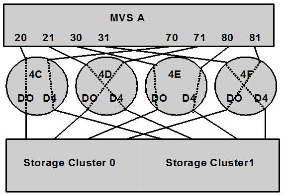
IOCP Example
Note the following:
-
From MVSA, you define 8 CHPIDs, with each path switched in the FICON Director, for a total of 8 channels running to the VSM 6 or VSM 7.
-
You code 16 CNTLUNIT statements to define the VSM 6/VSM 7 as 16 3490 images or if the VSM supports 512 VTDs, then code 32 CNTLUNIT statements. The 17th CNTLUNIT CUADD number would be 10 and the 32nd CNTLUNIT number would be 1F.
-
You code IODEVICE statements to define 16 VTDs that are associated with each 3490 image or if the VSM supports 512 VTDs, then code 32 IODEVICE statements.
FCD4C CHPID PATH=(20,70),TYPE=FC,SWITCH=4C
FCD4D CHPID PATH=(21,71),TYPE=FC,SWITCH=4D
FCD4E CHPID PATH=(30,80),TYPE=FC,SWITCH=4E
FCD4F CHPID PATH=(31,81),TYPE=FC,SWITCH=4F

CU1 CNTLUNIT CUNUMBR=001,
       PATH=(20,21,30,31,70,71,80,81),
       LINK=(D0,D4,D0,D4,D4,D0,D4,D0),
       UNIT=3490,CUADD=0,
       UNITADD=((00,16))

STRING1 IODEVICE ADDRESS=(0500,16),
       CUNUMBER=(001),
       UNIT=3490,
       UNITADD=00,STADET=Y

CU2 CNTLUNIT CUNUMBR=002,
       PATH=(20,21,30,31,70,71,80,81),
       LINK=(D0,D4,D0,D4,D4,D0,D4,D0),
       UNIT=3490,CUADD=1,
       UNITADD=((00,16))

STRING2 IODEVICE ADDRESS=(0510,16),
       CUNUMBER=(002),
       UNITADD=00,STADET=YUNIT=3490,
       .
       .
       .

CU15 CNTLUNIT CUNUMBR=015,
       PATH=(20,21,30,31,70,71,80,81),
       LINK=(D0,D4,D0,D4,D4,D0,D4,D0),
       UNIT=3490,CUADD=E,
       UNITADD=((00,16))

STRING15  IODEVICE ADDRESS=(05E0,16),
       CUNUMBER=(015),
       UNIT=3490,
       UNITADD=00,STADET=Y

CU16 CNTLUNIT CUNUMBR=016,
       PATH=(20,21,30,31,70,71,80,81),
       LINK=(D0,D4,D0,D4,D4,D0,D4,D0),
       UNIT=3490,CUADD=F,
       UNITADD=((00,16))

STRING16 IODEVICE ADDRESS=(05F0,16),
       CUNUMBER=(016),
       UNIT=3490,
       UNITADD=00,STADET=Y
Note:
Unlike ESCON, FICON supports multiple active I/Os per channel. If the number of active VTDs is less than the number of channels configured to the VTSS, the I/Os to those VTDs may not be evenly spread across all the channels. As the number of active VTDs increases to be greater than the number of channels configured to the VTSS, the channel subsystem will spread the I/Os across all the channels. If it is desired to spread the I/Os across all of the channels even when only a few VTDs are active, it is necessary to use the preferred path feature to force the channel subsystem to spread the I/Os across the channels. The preferred path feature is specified using the PATH= parameter on the IODEVICE statement. When you specify preferred path on the IODEVICE statement, the channel subsystem always tries the preferred path first. If it is busy or unavailable, the channel subsystem next tries the channel path following the preferred path in the rotation order, and so on.
The following example shows IODEVICE statements for STRING1 without using preferred pathing.
STRING1  IODEVICE ADDRESS=(0500,16),
       CUNUMBER=(001),
       UNIT=3490,
       UNITADD=00,STADET=Y
The following example shows IODEVICE statements for STRING1 using preferred pathing. If you are using preferred pathing, you need to use these kind of IODEVICE statements for all paths.
STRING10 IODEVICE ADDRESS=(0500,2),
       CUNUMBER=(001),
       UNIT=3490,
       UNITADD=00,STADET=Y,
       PATH=20

STRING12 IODEVICE ADDRESS=(0502,2),
       CUNUMBER=(001),
       UNIT=3490,
       UNITADD=00,STADET=Y,
       PATH=21

STRING14 IODEVICE ADDRESS=(0504,2),
       CUNUMBER=(001),
       UNIT=3490,
       UNITADD=00,STADET=Y,
       PATH=30

STRING16 IODEVICE ADDRESS=(0506,2),
       CUNUMBER=(001),
       UNIT=3490,
       UNITADD=00,STADET=Y,
       PATH=31

STRING18 IODEVICE ADDRESS=(0508,2),
       CUNUMBER=(001),
       UNIT=3490,
       UNITADD=00,STADET=Y,
       PATH=70

STRING1A IODEVICE ADDRESS=(050A,2),
       CUNUMBER=(001),
       UNIT=3490,
       UNITADD=00,STADET=Y,
       PATH=71

STRING1C IODEVICE ADDRESS=(050C,2),
       CUNUMBER=(001),
       UNIT=3490,
       UNITADD=00,STADET=Y,
       PATH=80

STRING1E IODEVICE ADDRESS=(050E,2),
       CUNUMBER=(001),
       UNIT=3490,
       UNITADD=00,STADET=Y,
       PATH=81
Using HCD to Define a VSM 6/VSM 7
The following sections tell how to use HCD to define a VSM 6 or VSM 7.
-
"Define the VSM 6/VSM 7 As Sixteen 3490 Images and Connect Them to the FICON Channels"
-
"Define 16 VTDs for Each Control Unit"
Note:
-
The following sections show procedures for using HCD to define a VSM 6 or VSM 7, not the actual HCD panels. For more information, refer to the IBM HCD documentation.
-
You may not need to do all of the above tasks (if, for example, you have already defined the FICON channels).
-
Define the FICON Channels
Using the values shown in Figure K-1, define (and dedicate) the FICON channels to MVSA, with each path switched in the FICON Director, for a total of 8 channels running to the VSM 6 or VSM 7 as follows:
-
Select a processor from the Processor List panel.
-
Select the Work with attached channel paths action from the context menu.
-
Press PF11 to display the Add Channel Path panel.
-
Use the Add Channel Path panel to add 8 channels to the processor.
For each channel, complete the channel path details as shown in Table K-3. Assuming that the FICON switches are pre-defined, enter the dynamic switch number and the entry switch number and port number. The entry port is the port where the channel is physically plugged in. The dynamic switch is the switch number of the FICON Director where the dynamic connection takes place. In the case of single switches in each channel path, the entry switch ID is the same as the dynamic switch ID.
Table K-3 Add Channel Path Values
Configuration Mode Number of CHPIDs Channel Path Type Operation Mode Channel Path ID Dynamic Switch ID Entry Switch ID Entry Port LPAR
1
FC
DED
20
4C
4C
F0
LPAR
1
FC
DED
70
4C
4C
F1
LPAR
1
FC
DED
21
4D
4D
F0
LPAR
1
FC
DED
71
4D
4D
F1
LPAR
1
FC
DED
30
4E
4E
F0
LPAR
1
FC
DED
80
4E
4E
F1
LPAR
1
FC
DED
31
4F
4F
F0
LPAR
1
FC
DED
81
4F
4F
F1
-
For each channel, the Define Access List panel is displayed.
Select MVSA from the Partition Name Number Usage Description list.
Define the VSM 6/VSM 7 As Sixteen 3490 Images and Connect Them to the FICON Channels
Define the 3490 images and connect them to the FICON channels as follows:
-
Select Control Units from the Define, Modify or View Configuration Data panel.
-
On the Control Unit List panel, Press PF11 to display the Add Control Unit panel.
For each control unit, complete the control unit details as shown in Table K-4.
Note:
HCD may provide default values for the protocol and I/O concurrency level fields, depending on the control unit type being defined.VSM7 VTSS support 512 VTDs with current maintenance. Control unit numbers 011 – 020 and CUADD number 10 – 1F are for VTDs 256 – 511. If your VSM does not support 512 VTDs, these Control Units do not need to be coded.Table K-4 Add Control Unit Values
Control Unit Type Channel Path IDs Control Unit Number Unit Address Number of Units Logical Address = CUADD 3490
20, 70, 21, 71, 30, 80, 31, 81
001
00
16
0
3490
20, 70, 21, 71, 30, 80, 31, 81
002
00
16
1
3490
20, 70, 21, 71, 30, 80, 31, 81
003
00
16
2
3490
20, 70, 21, 71, 30, 80, 31, 81
004
00
16
3
3490
20, 70, 21, 71, 30, 80, 31, 81
005
00
16
4
3490
20, 70, 21, 71, 30, 80, 31, 81
006
00
16
5
3490
20, 70, 21, 71, 30, 80, 31, 81
007
00
16
6
3490
20, 70, 21, 71, 30, 80, 31, 81
008
00
16
7
3490
20, 70, 21, 71, 30, 80, 31, 81
009
00
16
8
3490
20, 70, 21, 71, 30, 80, 31, 81
00A
00
16
9
3490
20, 70, 21, 71, 30, 80, 31, 81
00B
00
16
A
3490
20, 70, 21, 71, 30, 80, 31, 81
00C
00
16
B
3490
20, 70, 21, 71, 30, 80, 31, 81
00D
00
16
C
3490
20, 70, 21, 71, 30, 80, 31, 81
00E
00
16
D
3490
20, 70, 21, 71, 30, 80, 31, 81
00F
00
16
E
3490
20, 70, 21, 71, 30, 80, 31, 81
010
00
16
F
3490
20, 70, 21, 71, 30, 80, 31, 81
011
00
16
10
3490
20, 70, 21, 71, 30, 80, 31, 81
012
00
16
11
3490
20, 70, 21, 71, 30, 80, 31, 81
013
00
16
12
3490
20, 70, 21, 71, 30, 80, 31, 81
014
00
16
13
3490
20, 70, 21, 71, 30, 80, 31, 81
015
00
16
14
3490
20, 70, 21, 71, 30, 80, 31, 81
016
00
16
15
3490
20, 70, 21, 71, 30, 80, 31, 81
017
00
16
16
3490
20, 70, 21, 71, 30, 80, 31, 81
018
00
16
17
3490
20, 70, 21, 71, 30, 80, 31, 81
019
00
16
18
3490
20, 70, 21, 71, 30, 80, 31, 81
01A
00
16
19
3490
20, 70, 21, 71, 30, 80, 31, 81
01B
00
16
1A
3490
20, 70, 21, 71, 30, 80, 31, 81
01C
00
16
1B
3490
20, 70, 21, 71, 30, 80, 31, 81
01D
00
16
1C
3490
20, 70, 21, 71, 30, 80, 31, 81
01E
00
16
1D
3490
20, 70, 21, 71, 30, 80, 31, 81
01F
00
16
1E
3490
20, 70, 21, 71, 30, 80, 31, 81
020
00
16
1F
When you are finished, press Enter to display the Select Processor / Control Unit panel.
-
Select MVSA from the Select Processor / Control Unit panel and the Select (connect, change) action on the context menu.
When you are finished, press Enter to display the Select Processor / Control Unit panel. Note that Yes in the Att column indicates that the control unit is connected to the processor in the same row.
Define 16 VTDs for Each Control Unit
Define 16 VTDs and connect them to each control unit as follows:
-
On the Define, Modify or View Configuration data panel, select option I/O devices to display the I/O Device List panel.
-
Press F11 to display the Add Devices panel.
Complete the Add Devices panel. When you add a range of devices and you specify the first device serial number or a general description, you are prompted for the serial numbers of the other devices and can modify the description of each device.
VSM7 VTSS support 512 VTDs with current maintenance. Device numbers 0600 – 06F0 and CUADD numbers 10 – 1F are for VTDs 256 – 511. If your VSM does not support 512 VTDs, these devices do not need to be coded.
Device Type Device Number Unit Address Number of Units Logical Address = CUADD 3390
0500
00
16
0
3390
0510
00
16
1
3390
0520
00
16
2
3390
0530
00
16
3
3390
0540
00
16
4
3390
0550
00
16
5
3390
0560
00
16
6
3390
0570
00
16
7
3390
0580
00
16
8
3390
0590
00
16
9
3390
05A0
00
16
A
3390
05B0
00
16
B
3390
05C0
00
16
C
3390
05D0
00
16
D
3390
05E0
00
16
E
3390
05F0
00
16
F
3390
0600
00
16
10
3390
0610
00
16
11
3390
0620
00
16
12
3390
0630
00
16
13
3390
0640
00
16
14
3390
0650
00
16
15
3390
0660
00
16
16
3390
0670
00
16
17
3390
0680
00
16
18
3390
0690
00
16
19
3390
06A0
00
16
1A
3390
06B0
00
16
1B
3390
06C0
00
16
1C
3390
06D0
00
16
1D
3390
06E0
00
16
1E
3390
06F0
00
16
1F
-
Pressing Enter to display the Define Device to Operating System Configuration panel.
This panel lets you specify the operating systems to which the devices are to be defined. Select the Config ID, and the Select (connect, change) action to connect the devices to each operating system.
Note that YES is later shown in the Defined column to indicate that this device has been defined for the operating system in the same row.
Pressing Enter displays the Define Device Parameters / Features panel.
This panel allows device features to be specified to the selected operating system. Review the following MVS operating system features:
-
The OFFLINE feature defaults to the value specified in the UIM (which may not be appropriate for tape devices and ESCON directors).
-
The DYNAMIC feature defaults to Yes for devices that allow dynamic reconfiguration. Check your subsystems and applications that manage their own devices to make sure they support dynamically modified device control blocks (UCBs).
The status of a device may be changed from DYNAMIC=YES to DYNAMIC=NO, and vice versa, by a software-only dynamic change to a configuration. When changing from DYNAMIC=NO to DYNAMIC=YES, this must be the only change made to the device at that time. You are allowed, however, to make changes to a device that is currently defined as DYNAMIC=YES and at the same time change it to DYNAMIC=NO.
Note:
The DYNAMIC parameter is shown only when the appropriate device supports the dynamic I/O configuration function. -
The SHARED feature defaults to No. Since many MVS installations have more than one image, this parameter should be carefully checked and changed to "Yes" if appropriate.
-
-
Pressing Enter displays the Assign/Unassign Device to Esoteric panel.
-
Specify Yes or No to assign or unassign devices to the esoteric.
If you do not want to assign all the devices currently being defined to this esoteric, you can limit the devices being assigned by specifying a starting device number and the number of devices to be assigned.
-
Press Enter to go back through the panels to the Device List panel.