C ACSLS Support of the SL8500
This appendix discusses the following topics:
The following figure shows the SL8500 library with an ACSLS server.
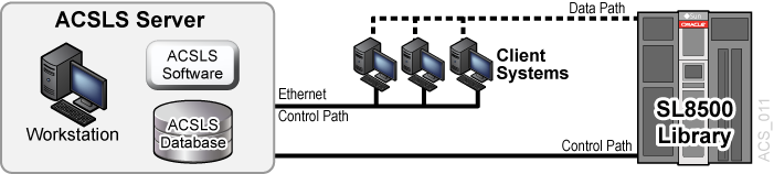
The SL8500 library uses TCP/IP protocol over an Ethernet physical interface to manage and communicate with the host and ACSLS. This interface enables ACSLS to connect to and communicate with the SL8500. Before you configure ACSLS for the SL8500:
-
Connect one or more SL8500s to ACSLS
-
Verify that all the components of the SL8500 are operational.
ACSLS builds its library configuration from the information reported by the library. If SL8500 components are not operational, the library information may not be reported to ACSLS, and the ACSLS configuration of the SL8500 will be incomplete.
Note:
If the components like drives or CAPs are not operational, it is easy to use Dynamic Configuration (config acs, config lsm, orconfig drives) to add or update them while ACSLS is running and the library is online.
Connecting to Multiple SL8500s Using Multi TCP/IP
When SL8500 3.97 or higher firmware is installed, ACSLS can connect to more than one SL8500 in an ACS (library complex).
ACSLS supports up to fifteen connections to an ACS. For example, this can be: fifteen connections to four SL8500s; two connections to each of two SL8500s; two connections to one SL8500 and two connections to two other SL8500s; three connections to two or three libraries, and so on.
When ACSLS is connected to more than one library, the connections should be through different subnets for redundancy. If one subnet fails, communication between ACSLS and the library still continues over the other subnet(s).
When ACSLS has two connections to one SL8500 HBC card, configure the SL8500 and ACSLS server routing tables, as described in "Overview". If you have only a single connection between the ACSLS server and each SL8500 library, configuring the ACSLS and SL8500 routing tables is not necessary.
To optimize library performance and minimize inter-library communication among SL8500s, connect to the libraries with the most activity. Make the first connection that you specify in acsss_config or config acs new to the SL8500 with the most activity.
For more information, refer to the SL8500 Modular Library System Technical Brief - Host to Library Communications.
Verifying that all SL8500 Components are Operational
To verify that all the components of the SL8500 are operational:
-
Logon to the StorageTek Library Console (SL Console).
You can use either the console on the SL8500 or a remote Library Console.
-
Select
Tools -> System Detail.-
All SL8500 components should be green.
Exception: Drives that are yellow can be configured now or later, using dynamic configuration ("bdb.acsss").
-
Missing components can be added using the Dynamic Configuration (
config acs or config lsm) utility. -
IMPORTANT: Before configuring the SL8500, the elevators (Elevator Folder) must be green. If the elevators are not green, do not configure the SL8500 to ACSLS. The elevators are the logical pass-thru-ports (PTPs). Without PTPs, ACSLS will not know that the SL8500 rails are connected.
-
-
Once the SL8500 components are operational, configure SL8500 to ACSLS, as discussed in "Setting CSI Tuning Variables" or under the "The acsss Macro".
Understanding SL8500 Internal Addresses and ACSLS Addresses
There are differences in the internal addresses of the SL8500 and other libraries supported by ACSLS and HSC.
-
The SL8500 is one's-based (1) and uses negative numbers.
-
Other libraries use a zero-based (0) with no negative numbers.
-
The SL8500 uses five parameters: library, rail, column, side, and row.
-
Legacy StorageTek libraries (such as 9310) use: ACS, LSM, panel, row, and column (HLI–PRC).
Table C-1 Addressing Descriptions
|
HLI–PRC |
SL8500 |
Description |
|
ACS |
Library |
Number of the specific SL8500 library in a library complex. An ACS is a SL8500 library complex. There can be multiple SL8500s in a library complex. |
|
LSM LSM 0 |
Rail Rail 1 |
The SL8500 library has four rails that the HandBots travel, which are numbered from top to bottom 1–4 (one's-based). ACSLS considers each rail to be a separate LSM, numbered from top to bottom 0–3 (zero-based). |
|
Panel Panel 0 |
Column CAP |
Columns indicate the horizontal location in the library. As viewed from the front of the library column and panel numbers start at the center of the drive panel (1) and sweep forward with increasing numbers. (The SL8500 does not use panels as an address.) An HLI panel spans across the width of the library to include both sides (left and right) and both walls (inner and outer) for each LSM. |
|
Side |
Wall location: Outer wall Inner wall HandBot number: Left (–) Right (+) |
|
|
Row |
Row |
Rows indicate the vertical location of a tape cartridge and are numbered from the top—down. |
|
Column |
Rows for the HLI address are: Storage panels start at 2 with Column 0 = left Rows 0–12 outer walls Rows 13–26 inner walls Each column in a normal storage panel has 27 rows. For a total capacity of 54 cartridges per panel. Rows for the SL8500 address are: Storage slots start at Rows 1–13 outer wall Rows 1–14 inner wall |
-
Zero-based numbering (as with HLI) starts numbering at 0.
-
One-based numbering (as with the SL8500) starts numbering at 1.
-
This is an important difference in the numbering sequences between software (ACSLS or HSC) and hardware (physical SL8500 addresses)
Using SL Console to Translate Addresses
Use the SL Console Search utility to translate between the SL8500 internal address and the ACSLS or HSC panel, row and column. To locate a cartridge:
-
Log in to the SL Console.
-
Select Tools >
Diagnostics > Search. -
Select Location.
-
Select one of the following operations in the
Locationfield:contains Example: 1,1,-9 lists the contents in Library 1, Rail 1, Column -9 for all rows on both sides endsWith Example: 1,5 lists the slot contents for all rails and columns for Side 1, Row 5 equals Example: 1,1,-9,1,1 lists the contents in that specific location (L,R,C,S,W) startsWith Example: 1, 3 lists the slot contents for all columns, sides, and rows in Library 1, Rail 3 -
Select one of the following from the
Requestorpull-down menu.-
defaultThe physical location inside the library (cell, drive, CAP).
If you know the physical location (the internal address), and need to find the HLI-PRC address,
enterthat address in thelocationand pickdefaultas the requester. -
hli#This selects the HLI-PRC address of the cartridge from the library management software where # is one of the following:
-
hli0 for a non-partitioned.
-
hli1-8 for a partitioned library, where the number is the partition number.
This option displays both the Internal Address and the
hli#Requester. -
-
-
Click the
Searchbutton in the top right corner of the SL Console.The search result lists the location by slot-type (cell, drive, or CAP).
-
Click the
Details (...)field.A pop-up window provides more information, such as: VOLID, media and cartridge type (LTO, SDLT tape, and T-Series, data, cleaning, or diagnostic) for cartridges, and shows both the internal and HLI addresses for the location.
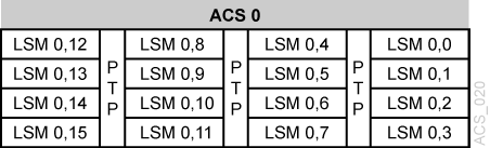
Tape Drive Locations
The tape drives are associated with, and belong to an LSM. To mount a cartridge tape in a different LSM, the cartridge must go through an internal pass-thru operation (in this case, the elevator) to the drive.
The following tables shows the internal—software—mapping (viewed from looking inside the library at the tape drives), and the external—physical numbering of the drives (looking outside at the rear of the Drive and Electronics Module).
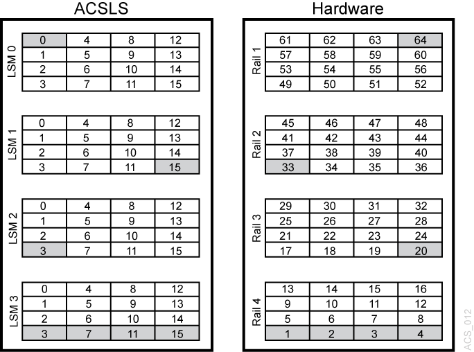
The highlighted drives show a matching drives. For example:
-
Internal/software LSM 0 Drive 0 matches with external/physical Drive 64.
-
Internal LSM 1 Drive 15 matches with external/physical Drive 33.
-
Internal LSM 2 Drive 3 matches with external physical Drive 20.
Moving Cartridges Before Removing Cells from a Partition
The SL8500 can partition down to the drive and cell array level with enhanced partitioning. For more information, refer to "Moving Cartridges Before Removing Cells from a Partition".
SL8500 CAPs
Beginning with ACSLS 8.4, two SL8500 CAP types are supported in ACSLS. The legacy Rotational type may have one or two 39-cell CAPs installed on each SL8500 library. The newest CAP type, the Bulk CAP, has eight 36-cell CAPS installed on each library.
Bulk CAP
Newer SL8500 libraries are designed for faster, more efficient enter and eject operations for data centers where large and frequent vaulting activities are common. There are eight Bulk CAPs on each SL8500 library, with one CAP on each side of each rail. Each CAP contains three removable 12-slot magazines.
ACSLS uses Bulk CAPs to efficiently enter and eject cartridges. Volumes entered from a CAP are moved to a slot on the same side and on the same rail as the CAP. If that side is full, an empty slot on the other side is selected. If the rail is full, an adjacent rail is selected. This strategy minimizes robotics movement and prevents contention between robots. Similarly, if ejecting.sh ejects a list of volumes, each volume is ejected to the nearest CAP among the CAPS that you specified. See "ejecting.sh".
To reserve an open slot in each magazine to serve as a handle during ejects, set the dynamic variable, BULK_CAP_EJECT_HANDLE, to TRUE using dv_config.
$ dv_config -p BULK_CAP_EJECT_HANDLE  -u

When ejecting cartridges to an SL8500 Bulk CAP, leave a slot in each CAP magazine empty so it can be used as a handle. (TRUE/FALSE) [FALSE]: TRUE

Updating configuration file.
When this variable is set to TRUE, eleven storage cells in each magazine are used for eject operations. The bottom cell in each magazine on the top three rails remains empty, and the top cell in each magazine on the bottom rail is empty. This enables you to use the empty slot as a handle. This setting does not affect behavior during enter operations.
With eight CAPs per module, there can be eight Bulk CAPs in a ten-string SL8500 configuration. In larger SL8500 complexes, CAP operations could delay mount and dismount operations when multiple enters and ejects are in progress. To mitigate this problem, the dynamic variable, LIMIT_CAP_CONCURRENT_MOVES, can limit the number of concurrent enter and eject robotic moves, allowing mounts and dismounts to proceed. To engage this feature, set the dynamic variable, LIMIT_CAP_CONCURRENT_MOVES, to TRUE using dv_config.
$ dv_config -p LIMIT_CAP_CONCURRENT_MOVES  -u

When using large numbers of CAPs for ejects and/or enters in an ACS with multiple libraries, limit the number of concurrent moves to/from CAPs to reserve library resources for mounts and dismounts. (TRUE/FALSE). [FALSE]: TRUE

Updating configuration file
Upgrading the SL8500 to Handle Bulk CAPs with ACSLS
To update ACSLS when installing Bulk CAPs in one are more SL8500s:
-
Install ACSLS 8.4.
This can be done far in advance of installing the Bulk CAPs.
-
The Oracle Field Service Engineer (FSE) must load and activate the SL8500 firmware that supports Bulk CAPs onto the affected SL8500s.
The minimum SL8500 firmware level is 8.50.
-
Before installing the Bulk CAP hardware, use ACSLS
cmd_procto vary the libraries offline where Bulk CAPs are installed.-
If you are installing Bulk CAPs in a stand-alone SL8500 or installing Bulk CAPs in all of the SL8500s in a string, vary the entire ACS (library complex) offline.
-
If you are installing Bulk CAPs in only some of the SL8500s in a library complex, you only need to vary the LSMs involved offline.
-
-
During this step the FSE installs the Bulk CAP hardware on the affected libraries.
-
Before the FSE installs Bulk CAP hardware, you must remove the cartridges in the three cell array columns closest to the service door and save them outside the library. (You will reenter the cartridges after the installation is complete.)
Reason: To install Bulk CAPs, two columns of system cell arrays must be removed plus the three-pack array. Most of the storage cells in the third column becomes system cells which are no longer accessible to ACSLS.
-
The FSE installs the Bulk CAP hardware on the libraries.
-
-
After all SL8500s have been re-booted and the library hardware audit is complete, use ACSLS
cmd_procto vary the SL8500 ACS to diagnostic mode.Diagnostic mode prevents ACSLS clients from accessing these libraries while the ACSLS configuration is being updated and the libraries are audited
-
With ACSLS running, use the
config acsacs_idutility to add the Bulk CAPs to the ACSLS configuration recorded in the database.Note:
You can also disable ACSLS, and runacsss_config, Option 8, to update the configuration. If you do this, runquery lmu allfromcmd_procand save the output before shutting ACSLS down. Then specify the ACSs toacsss_configwith the same ACS numbers and with the same port connections. Afteracsss_configis done, enable ACSLS -
Display and verify the cap status and type from an ACSLS
cmd_procwith:display cap * -f state mode status size type
Sample output:
0  0  0     online    automatic   available     36    SL8500-Bulk
0  0  1     offline   manual      available     36    SL8500-Bulk
0  1  0     online    automatic   available     36    SL8500-Bulk
0  1  1     offline   manual      available     36    SL8500-Bulk
0  2  0     online    automatic   available     36    SL8500-Bulk
0  2  1     offline   manual      available     36    SL8500-Bulk
0  3  0     online    automatic   available     36    SL8500-Bulk
0  3  1     offline   manual      available     36    SL8500-Bulk
-
Audit the libraries where Bulk CAPs were installed using
cmd_proc. You can either-
Audit the entire ACSLS:
audit <cap_id> acs <acs_id>
-
Audit just the LSMs where Bulk CAPs were installed:
audit <cap_id> lsm <lsm_id> <lsm_id> <lsm_id> <lsm_id> ...
-
-
Vary the ACS and LSMs online to ACSLS. using the
varycommand.ACSLS clients can now use the Bulk CAPs.
-
Use a CAP to reenter any cartridges that were taken out of the library in Step 4 above.
Custom SL Console Messages Showing Purpose of Enters and Ejects
The SL Console can display custom operator messages on the CAP Status screen that show the purpose for enters to and ejects from Bulk CAPs. These messages can also report the partition into which cartridges are being entered or the partition from which cartridges are ejected.
These operator messages are optional. They do not affect the underlying enter and eject processing, and they are only supported for SL8500 Bulk CAPs.
To use custom operator messages:
-
Define the message to be displayed for an
opmsgnumber using the SL Console. Select the following options.Tools Configuration CAP Usage MessageDefine a message number, from 4 through 99, and an associated message. If possible, limit the message to 20 characters, so it fits in the available space.
-
Enter the optional operator message number on manual enters or ejects:
enter<cap_id>[opmsg<opmsg_nbr>]eject<cap_id>[opmsg<opmsg_nbr>]vol_id | vol_range ...Custom
opmsgnumbers cannot be specified for ejects from ACSAPI clients, the ACSLS GUI, orlib_cmdeject. In these cases the default messages are displayed.The
opmsgmessage displays on the System Details, CAP Status page after a CAP is unlocked for cartridges to be entered, to be inserted, or cartridges being ejected to be removed.Example: To specify custom operator panel message number 55 when entering cartridges through Bulk CAP 1,2,1:
enter 1,2,1 opmsg 55
Rotational CAP
The SL8500 Rotational CAP spans three rails (2,3,4) corresponding to LSMs 1, 2, and 3. The base configuration includes one CAP per SL8500 module, and a second CAP that can be installed as an option.
Each Rotational CAP has three magazines with 13 cells each. The magazines are situated each on a different rail, accessible only to the handbots on that rail. During an enter, ACSLS attempts to move cartridges from each magazine to the adjacent LSM (rail). Only if the adjacent rail is full will the volume be moved to a different rail Similarly, volumes on a given rail are ejected to the adjacent magazine on that rail.
Since the top rail (LSM 0) does not have an adjacent CAP magazine, an elevator move automatically comes into play with volumes ejected from the top rail. On enters, the top rail is not populated until a lower rail is filled to capacity. Volumes mounted to drives on the top rail eventually migrate to the top LSM when they are dismounted. Otherwise, an explicit move operation is needed to situate volumes in the LSM on the top rail. Such an extra move can be handled automatically after an enter with the watch_vols utility. See "watch_vols".
Because the single Rotational CAP serves multiple LSMs, the Rotational CAP state is not tied to the online or offline state of any LSM. The CAP can remain online whether any one or all of the adjacent LSMs are offline. Conversely, if the CAP is offline, it is not be brought online automatically when any LSM is varied online.
Even though multiple LSMs access the CAP, the SL8500 Rotational CAP is addressed as though it was in LSM 1 (such as 1,5,9,13). In a partitioned library where each partition is assigned to a different host, users must be aware that the CAP is a shared resource. A Rotational CAP becomes reserved immediately upon an enter or eject operation. Operators in shared environments should promptly fill or empty the CAP and close the door upon completion of the CAP operation. See "Library Partitioning".
Older releases of the SL8500 had reported the optional CAP as present but not operational if the second CAP was not actually installed. As a work-around, ACSLS users were instructed to keep the desired state of the non-existent CAP offline.This is no longer an issue beginning with library firmware level 6.07 and above.
Enter or Eject Operations
During an enter, ACSLS will always try to move the cartridge to an LSM (rail) adjacent to the CAP magazine. For ejects, ACSLS will always try to eject cartridges to a CAP cell adjacent to the LSM containing the cartridge
If these two operations are not possible, the library controller takes care of moving the cartridge through the elevator to another LSM. This requires movements between two handbots and the elevator.
Enter, Eject, and Audit Operations for Some ACSLS Clients
Unlike other libraries, the SL8500 does not have CAPs defined for each LSM ID in an SL8500 library. The CAPs on an SL8500 contain LSM 1 in their CAP IDs. There are no CAPs in an SL8500 with LSM IDs 0, 2, or 3. Partitioning complicates this problem because LSM 1 (the LSM ID in the SL8500 CAP ID) may not be assigned to your partition. (Remember, the CAPs are still available to all partitions as a shared resource).
Some ACSLS clients do not query ACSLS to identify which CAPs exist and are available before selecting a CAP for an enter, eject, or audit. They may specify cap_ids that do not exist, or CAPs that are not online. For example, some ACSAPI clients assume CAPs exist for all LSM IDs. They may automatically specify a CAP with the same LSM ID as the location of cartridges or drives that they manage. Enters, ejects, or audits that specify non-existent CAP IDs will fail.
You must use the ACSLS cmd_proc to:
-
enterandejectcartridges for clients that specify non-existent CAP IDs. -
run audits for any ACSs and partitions used by these clients.
After entering, ejecting, or auditing, you must re-synchronize the client application's database with the ACSLS database.
Minimizing Elevator and PTP Activity
There are several things you can do to minimize elevator and PTP activity, such as:
Configuring Tape Drives to Support Your Workloads
How tape drives are configured in the SL8500 can minimize both elevator and PTP activity, while supporting your tape workloads. Strategies to use in determining where tape drives are located in the SL8500 include:
-
Cluster cartridges by workload, with enough drives to support the maximum drives needed for the workload. Separate the cartridges used by each workload on separate rails, and ensure the rail(s) dedicated to a workload has enough drives to meet the maximum concurrent mounts for the peak usage of the workload. Ensure that the rail has not only the tape cartridges for the workload, but also the scratch cartridges that will be needed.
-
Allocate separate rail(s) to each major application workload. This is because some applications, such as Symantic NetBackup and Tivoli, can use their own media and drives.
-
Clustering drives and media on a single rail works until the mounts per hour threshold is reached, all drives are in use, or there are too many active cartridges to fit on a rail. When the resources needed for a workload exceeds the capacity of a rail, spread the cartridges and drives over two or more rails.
-
Cluster drives by type, placing drives that use different media types on separate rails (LSMs). For example, place T9840 drives on one rail and T10000 drives on a different rail.
-
Configure your heavy tape applications so they will not exceed the performance limits of your library configuration.
-
Configure the SL8500 with 8 HandBots (two HandBots per rail) to provide redundancy. This allows you to always access the cartridges and drives that support a workload.
Managing Cartridge Locations
How cartridges are originally entered in the library, or their status in the library, can have an affect on ACSLS performance. Considerations, are:
Finding Missing Cartridges
If a cartridge is out of place or unaccounted for by ACSLS:
-
Perform a physical audit of the SL8500 using the SL Console.
The physical audit of the SL8500 is performed as a background task in between handling mount and other library operation requests.
Caution:
If the SL8500 contents are out of sync with ACSLS due to manual operations such as loading cartridges directly, it is not advisable to attempt continued operations.If you want to manually add tapes, adding them to a particular LSM within the SL8500 is a better approach. Adding tapes to a particular LSM and auditing only the affected LSM is a quicker and more reliable solution.
You must
varythe affected LSM to a diagnostic state to ACSLS while the audit is in process. After the SL8500 library audit is performed,varythe LSM online to ACSLS. -
Run an ACSLS
auditto update the ACSLS database to match the actual inventory of library cartridges.
Varying the SL8500 Offline
Vary SL8500 components offline to ACSLS before they are powered off, if they are inoperative, and before you open an SL8500 access door. This notifies ACSLS that they are unavailable. Once they are available, vary them back online.
Use ACSLS to vary SL8500 components offline, not SL Console
Vary SL8500 components (ACSs, LSMs, and CAPs) offline to ACSLS, not the SL Console.
ACSLS allows outstanding requests to complete before taking components offline, unless it is a vary offline force. The SL Console has no knowledge of outstanding requests to ACSLS.
Varying components offline using SL Console may cause requests in progress to fail.
When to vary SL8500 components offline to ACSLS
This section discusses when to vary SL8500 components offline to ACSLS.
Before opening the access door
Before opening the SL8500 access door, vary the ACS or all four LSMs offline.
-
For a standalone SL8500,
varythe ACS offline using the following command:vary acsacs_idoffline -
For a SL8500 connected through PTPs,
varyall four LSMs (in the SL8500 whose access door will be opened) offline using the following command four times (once for each of the four LSMs):vary lsmlsm_idofflineNote:
If any CAPs in the SL8500 are in automatic mode, you must:
-
Set them to manual mode before opening the access door.
-
Set them back to automatic mode after you close the access door and the SL8500 comes back online.
If a CAP is inoperative
If the CAP is inoperative, vary it offline using the following command:
vary cap cap_id offline
When closing the Service Safety Door
Whenever replacing hardware requires using the Service Safety Door, it is advisable to keep that Service Safety Door closed for the minimum amount of time possible. The Service Safety Door blocks other hardware components (elevators, CAPs, and cells) to which access may be required for completing specific requests.
-
Before closing the Service Safety Door on either the left or right-side of the SL8500,
varythe elevator on that side offline through the SL Console.After the Service Safety Door is opened,
varythe elevator on that side back online through the SL Console. -
When the Service Safety Door is closed on the right-side, it will block access to the CAP.
-
Before closing the Service Safety Door on the right-side of the SL8500,
varythe CAP offline through ACSLS. -
After the Service Safety Door is opened,
varythe CAP online through ACSLS.Note:
When the SL8500 Service Safety Door is closed to separate a service bay from the rest of the library, the CSE can open the access door on that side without taking the LSM or ACS offline.
When using the Service Safety Door do not use these ACSLS commands and utilities
There are some ACSLS commands and utilities that should not be in progress or initiated when the Service Safety Door is being used. These commands, are:
When the Service Safety Door is closed on either side, do not use the following utilities:
-
acsss_config -
config (config drivesis OK)
When the Service Safety Door is closed on the right (CAP) side, do not use the following commands:
-
enter -
eject -
set cap mode auto <cap_id>
When the Service Safety Door is closed on the right (CAP) side, the following commands can be used, but special considerations apply:
-
auditThe audit command can be used. However, if there is a need to
ejectcartridges as a result of the audit (because the audit encounters duplicates or unreadable labels), the audit will complete and update the ACSLS database, but the cartridges will not be ejected. -
vary acsandvary lsmThese commands will succeed, but messages will be displayed on
cmd_procand the Event Log reporting CAP failures and inoperative CAPs.
Using the Dynamic Configuration (config) utility
The dynamic configuration (config) utility allows you to implement configuration changes to ACSLS libraries (and components) while ACSLS remains online and running. These configuration changes are recorded in the acsss_config.log file.
The following dynamic configuration utilities are supported:
-
config acs -
config drives -
config lsm -
config ports
Using the config utility provides the following benefits:
-
ACSLS can continue running, allowing you to perform
mountrequests to unaffected library components. -
Allows you to reconfigure specified library components while all other configuration information remains unchanged. For example, when specifying:
-
An ACS, the configurations of other ACSs are not affected.
-
An LSM, the configurations of other LSMs are not affected.
-
A drive panel, the drives on a panel, mounts and dismounts to all existing drives are not affected.
-
Expanding the SL8500
Storage Expansion Modules (SEMs) are added to the SL8500 to increase its capacity. The SEMs are inserted between the Customer Interface Module (CIM), which includes the CAP, and the SEM or Robotics Interface Module (RIM) that is currently attached to the CIM.
When an SL8500 is expanded:
-
The library configuration changes, and you must reconfigure ACSLS using either the ACSLS Dynamic Configuration utility while ACSLS is up, or run
acsss_configwhile ACSLS is down. -
Cartridges must be removed to expand the SL8500. When placing these cartridges back into the library, leave the cell arrays that they were formerly in, empty.
-
After the expansion is complete, the SL8500 must be rebooted twice. First to discover the new configuration, and second, to restart all library components with the updated configuration.
-
The library must update the locations of all cartridges with a physical audit.
The library begins a physical audit automatically when the access door is closed. The library's physical audit completes when all robot movement stops for at least a minute.
-
After the library's physical audit is complete, use the procedure "Auditing an Expanded SL8500" to update the ACSLS database.
Note:
Do not start automated library operations until the ACSLS audits are complete, and the ACSLS database has been updated with the new cartridge locations.
What is Involved
Physically expanding an SL8500 involves the following:
-
A new SEM(s) is inserted between the existing SEMs or RIM and the CIM.
The panel numbers on the new SEM(s) and the CIM are now higher than the panel numbers on the existing SEMs and RIM.
-
Because the CIM must move out, new and higher panel numbers are assigned to the three cell panels (columns) on the CIM. When the cell panels on the CIM are assigned higher panel numbers, the addresses of all cartridges on the CIM change.
-
Many cartridges must be removed to expand the SL8500. Cell arrays must be removed to both unbolt existing rails, and bolt-in new ones, to jack-up the CIM.
-
After the new rails are installed and the SL8500 is expanded, the cartridges that were removed may be loaded back into the library. Leave the cell arrays that were temporarily removed to expand the library, empty.
After expansion, audit the library so ACSLS can update its database with the new addresses of these cartridges. When cartridges are placed in new locations, ACSLS' attempts to find the cartridges that were previously in the cells can seriously degrade library performance during an audit. To optimize both ACSLS and library performance, complete the following procedure:
-
Let the library's physical audit complete before starting an ACSLS audit. The combined audits will finish faster if the library is able to report cartridge locations to ACSLS from its database. Otherwise, the library must re-verify cartridge locations before responding to ACSLS'
auditrequests. -
For the cartridges that were removed to expand the library, use one of these strategies to re-insert them back into the library:
-
Remove the cartridges from the library,
auditthe library from ACSLS, thenenterthe cartridges that were removed back into the library. -
Insert the cartridges only into the panel numbers that were added to the library, then
auditthese panels, first.If you are not using ACSLS scratch pools to track scratch cartridges, no special procedure is required, if you have absent volume retention enabled (the default). When you
auditthe library, the cartridges that were moved are often marked absent, butauditfinds them in their new locations and reactivates them. The location of the cartridges is updated, and no important information is lost.If you are managing scratch cartridges by assigning cartridges to ACSLS scratch pools, and you do not want to have the cartridges' scratch status cleared, place the cartridges in the newly added panels, and
auditthese panels, first.-
Insert the cartridges that were removed into the panels that were added to the library. This means, only insert them into panels (columns) beyond the three panels that are closest to the drives in the first new SEM. (The first three panels in the first SEM have the panel numbers that were formerly assigned to the three panels in the CIM.
-
Then,
auditthe panels in the ACS or LSMs from the highest panel number down, through all of the new panel numbers that were added:Use
auditcap_idpanelpanel_id commands. -
Finally,
auditthe rest of the ACS or LSMs:Use the
auditcap_idacsacs_id or
auditcap_idlsmlsm_id commands.
This procedure is described in full detail in "Auditing an Expanded SL8500".
-
-
Diagram of SL8500 Modules:
In the following diagram, the three cell panels in the Customer Expansion Module (#5) are the three columns of cartridges on both the outside and inside walls on the drive side of the CEM. These are the only cell addresses in the CIM that HandBots can access when the service safety door is activated.
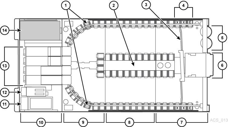
Legend:
-
Cartridge Access Ports (2) Caps
-
Facade Operator Panel (Optional) Icey Pad
-
Customer Interface Module
-
Storage Expansion Module
-
Robotics Interface Module
-
PTP (Pass Thru Port)
-
Drive Electronics Module
-
AC Power Supplies Electronic Control Module
-
DC Power Supplies
-
Tape Drives
-
Accessory Racks
-
Inner wall
-
Service Door
-
Reserved Columns
-
E = End Stop
-
S = System Cell
-
Auditing an Expanded SL8500
Before expanding the SL8500:
-
If you want to preserve the cartridges' scratch status:
-
Determine the highest panel number for the LSMs in the library by running the following command:
display panelacs,lsm,*Where:
-
acsis the ACS -
lsmis one of the LSMs. All rails (LSMs) on the SL8500 have the same number of panels. -
*displays all panels in the LSM.
-
-
Record the highest panel number.
-
-
Varythe LSMs to a diagnostic state until the configuration is updated and cartridge addresses have been updated withaudit. -
Backup the ACSLS database.
-
Expand the SL8500:
During the expansion, cartridges must be removed to install new or expanded rails, and to add the Storage Expansion Modules.
Note:
Do not insert these cartridges back into the cell arrays that were temporarily removed to expand the library. This avoids a severe degradation in library performance when these locations are first audited. -
Insert the cartridges that were removed into the panels that were added to the library.
This means, you should only insert these cartridges into panels (columns) beyond the three panels that are closest to the drives in the first new Storage Expansion Module. (The first three panels in the first Storage Expansion Module retain the numbers formerly assigned to the panels in the CIM.)
After physical expansion of the SL8500 is complete:
-
Reboot the library twice.
-
Leave the LSMs in a diagnostic state.
-
Update the configuration in the ACSLS database using one of the following methods:
-
ACSLS is running:
config acsacs_idor, for each LSM (rail) in the SL8500:
config lsmlsm_id -
Shutting down ACSLS:
-
Bring down ACSLS:
acsss disable -
Update the ACSLS configuration:
acsss_config -
Bring up ACSLS:
acsss enable
-
If you want to preserve the cartridges' scratch status,
auditthe library using steps 9 through 11. If you are not tracking the cartridge scratch status using ACSLS scratch pools, skip to step 12. -
-
Determine the new highest panel number for the LSMs in the library, and record this number using the following command:
display panelacs,lsm,*Where:
-
acsis the ACS. -
lsmis one of the LSMs. All rails (LSMs) on the SL8500 have the same number of panels -
*displays all panels in the LSM.
-
-
Auditthe panels that were added during the expansion, from the new highest panel number to the old highest panel number+1.Auditthese panels in descending order using the following command:auditcap_idpanelpanel_idWhere:
-
cap_id is the CAP where cartridges with duplicate
vol_idsor unreadable labels should be ejected. -
panel_id is the panel being audited (
acs,lsm,panel)
-
-
Perform a separate audit for each added panel in each LSM.
Note:
You can only run as many concurrent audits as you have CAPs in your library complex. Each concurrent audit needs a separate CAP. If the audit ejected any cartridges to the CAP, they must be removed before the audit finishes. -
Auditeach entire LSM in the expanded SL8500 (or audit the entire ACS). -
Backup the ACSLS database.
-
Varythe LSMs online. -
Resume automated library operations.
Connecting SL8500s with Pass-Thru-Ports
You may need to audit SL8500(s) to update cartridge addresses when adding SL8500 libraries to an existing SL8500 library complex.
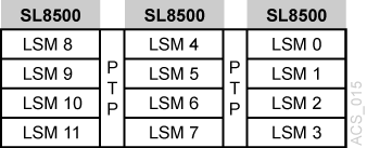
LSMs in the SL8500 complex are numbered from top-down and right-to-left when viewed from the CAP end, as shown in the following figure.
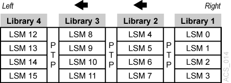
Depending on how your site is set up, you may be adding a new SL8500 to the right or left of an existing SL8500. As a result:
-
When a a new SL8500 is added on the left, the new LSMs have higher numbers, and existing LSMs are not renumbered. The disruption is minimal.
-
When a new SL8500 is added on the right, all existing LSMs are renumbered. This causes the home cell addresses of all existing cartridges to change.
Before You Install SL8500 PTP Connections
-
Apply all relevant maintenance to ACSLS before installing SL8500 connections.
-
Enable absent cartridge support.
When absent cartridge support is enabled, ACSLS will not delete cartridges in an LSM that is deleted or when
auditdoes not find them in their old address. These cartridges are marked absent, preserving all information about them, except for the scratch status. When these cartridges are later found byaudit, they are reactivated.-
Absent cartridge support is enabled when the
ABSENT_VOLUME_RETENTION_PERIODvariable is not zero. The default value is 5 days. -
Use
acsss_config(option 3). For procedures, refer to "Setting CSI Tuning Variables" and the variableABSENT_VOLUME RETENTION_PERIOD.
-
-
Update your configuration by one of the following methods:
-
With ACSLS up, use the following command:
config acsacs_id -
Shutting ACSLS down, use the following command:
-
Bring down ACSLS:
acsss disable -
Update the ACSLS configuration:
acsss_config -
Bring up ACSLS:
acsss enableACSLS cannot be running when you run
acsss_config.For more information, refer to "Setting CSI Tuning Variables" or under the "The acsss Macro".
-
-
Adding New SL8500s
When additional SL8500s are added to an existing SL8500 library complex, the new ACSLS configuration must be updated. If the addition of new SL8500s causes the LSMs in the existing SL8500s to be renumbered, the cartridge addresses in those LSMs must be updated.
The cartridge addresses should be updated without losing the other information associated with the cartridges. This includes cartridge information, such as scratch status, pool, locks, and ownership and cleaning cartridge usage counts, and the date and time that cartridges were entered.
LSMs in connected SL8500s are numbered from top-to-bottom and right-to-left (as viewed from the CAP end).
Adding a New SL8500 to the Left
In the case of the non-disruptive addition of a new SL8500 on the left (from the CAP end) of the original SL8500(s), use the host software (ACSLS) to dynamically configure the additional drives and libraries.You do not need to recycle ACSLS if Dynamic Configuration is installed. Mount requests continue as normal to the existing SL8500s during this phase.
If cartridges were placed in cells in the new SL8500, an ACSLS audit must be run on the LSMs of the new SL8500 to add these cartridges to the ACSLS database.
The LSMs in the pre-existing SL8500s can be online during the audit.
Dynamically Configuring the New ACSLS Configuration
-
Add new SL8500(s) to the library complex.
-
Backup ACSLS before you make the configuration change.
-
Update the ACSLS configuration dynamically, use the following command:
config acsacs_idYou can also update the ACSLS configuration when ACSLS is down, use the following command:
acsss_config -
Backup ACSLS after you make the configuration change.
Note:
If there are cartridges in the new SL8500,auditthe LSMs (rails) in the new SL8500 to add these cartridges to the ACSLS database.
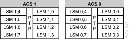
Adding a New SL8500 to the Right
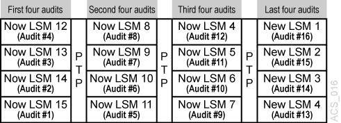
If you want to add a new SL8500 to the right, the existing LSMs will be renumbered, as shown in the following figures.
Considerations When Adding an SL8500 to the Right
When new SL8500s are added to the right, all existing LSMs will be renumbered and cartridge addresses will change. The change to LSM numbers causes all existing cartridge addresses to change. If ACSLS attempts to mount a cartridge whose address changed, the mount will fail because ACSLS cannot find the cartridge.
-
Quiesce mount activity until all cartridge addresses have been updated.
-
Varyall LSMs in the ACS to diagnostic state to prevent mounts. -
Update the cartridge addresses by auditing the LSMs in the existing and new SL8500s in a specific sequence.
Dynamically Configuring the New ACSLS Configuration
To a update the ACSLS Configuration Dynamically after adding a new SL8500(s):
-
Varyexisting LSMs in diagnostic state (varylsm_iddiag).Caution:
These LSMs must remain in diagnostic state until they have been audited. Otherwise, the following problems will occur:-
Mounts will fail because cartridges cannot be found in their last-known addresses.
-
Until the audits update the ACSLS map of the empty cells in the renumbered LSMs:
-
Enters of new cartridges will collide with existing cartridges.
-
Movements of cartridges to existing (renumbered) LSMs will collide with cartridges already in the cells.
-
-
-
Add the new SL8500(s) to the library complex.
-
Backup ACSLS (before making any configuration changes).
-
Update the ACSLS configuration dynamically using the following command:
config acsacs_idNote:
As an alternative, update the ACSLS configurations while ACSLS is down. First, bring ACSLS down using theacsss disablecommand. Change the configuration withacsss_config, and finally, bring ACSLS back up withacsss enable.Note:
New LSMs are added when in an online state.Varythese LSMs to a diagnostic state until they have been audited. -
Backup ACSLS (after the configuration change).
-
Auditthe library to update cartridge addresses (since they were renumbered).Use the following sequence:
-
A
uditeach LSM in the pre-existing SL8500s that were renumbered.-
Auditthe pre-existing SL8500s in a careful sequence to avoid losing cartridges.Auditeach LSM (rail) in sequence from the highest numbered LSM to the lowest numbered LSM ID. The audit finds all of the cartridges in their (renumbered) LSM addresses. -
For ACSLS, you must
auditeach LSM separately, and allow the audit of one LSM to finish before auditing the next LSM.Auditchecks the cartridges' former home cell addresses (in the LSM to the right), and then updates the cartridges' addresses. The audits for the LSMs in the left most SL8500 will take a long time. The audits in all of the other SL8500s will be faster.The reason that the audits of the left of most LSMs take longer is that they will trigger a cascade of
Cartridge Recoveryrequests. When audit finds a cartridge that has a different home cell address,auditchecks the cell address recorded in the database. If that cell has a different cartridge,Cartridge Recoveryinvestigates that cartridge, and so on. Because all of the LSM addresses have changed, these recoveries will cascade across the SL8500 library complex. -
Keep the LSMs in diagnostic state until they have been audited. After they have been audited, you can
varythem online.Audithas updated the addresses of cartridges in this LSM, so you can resume automatedmountactivity with the audited LSMs' cartridges.
-
-
Last,
auditthe LSMs in the newly added SL8500 (that have the lowest LSM IDs).After these LSMs have been audited, they can be varied online, and cartridges in them can be mounted on tape drives, as shown in the following figures.
-
-
Backup ACSLS after the audits have completed.
Procedures for Merging ACSs
SL8500 PTP supports the merging of multiple, separate SL8500s into a single ACS. To minimize the loss of information about cartridges and operational downtime, follow these recommended procedures.
Note:
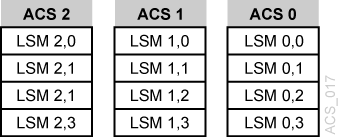
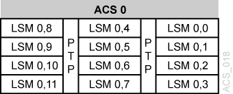
When the ACSLS configuration is updated, global cartridge address changes are not made.For ACSLS, two scenarios are described below. In the first, the ACSs to be merged are numbered from right-to-left (as you face them from the CAP-side). In the second, they are numbered from left-to-right. It is assumed that the resulting ACS will use the lower/lowest ACS ID.
Merging ACSs Numbered from Right to Left
In the following scenario, the ACSs to be merged are numbered from right-to-left (as you face them from the CAP side).
Procedure for Merging ACSs Numbered from Right-to-Left
-
Varyall ACSs, except the right most ACS being merged, offline.This prevents mounts and dismounts while cartridge addresses are being updated.
-
StopACSLS:acsss disable -
Backup ACSLS before making any configuration changes.
-
Update the ACSLS configuration (while ACSLS is down) using
acsss_config -
Bring up ACSLS:
acsss enable -
Varythe new LSMs (that were added to the ACS) to a diagnostic state.These LSMs were added while in online state.
-
Backup ACSLS after the configuration change.
-
Auditthe LSMs that were added to the ACS.The order in which they are audited does not matter. The entire ACS, or all LSMs can be audited at once.
The cartridges will be re-activated.
-
Backup ACSLS after the audits are complete.
-
Varythe new LSMs online, and resume normal automated processing.
Merging ACSs Numbered from Left-to-Right
In the following scenario, the ACSs to be merged are numbered from left-to-right.

Procedure for Merging ACSs Numbered from Left-to-Right
-
Varyall ACSs offline.This prevents mounts and dismounts while cartridge addresses are being updated.
-
StopACSLS:acsss disable. -
Backup ACSLS before making any configuration changes.
-
Update the ACSLS configuration (while ACSLS is down) using
acsss_config. -
Bring up ACSLS:
acsss enable. -
Varythe new LSMs (that were added to the ACS) to a diagnostic state.(These LSMs were added while in online state).
-
Backup ACSLS after the configuration change.
-
Varythe new LSMs that were added to the left, to a diagnostic state.You do not want to perform mounts and dismounts until you have audited these LSMs.
-
Auditthe newly configured LSMs.The order in which they are audited does matter.
Auditin this order:-
First, audit the LSMs in the SL8500(s) that retains the same ACS number first.
-
You want
auditto find these cartridges in their new LSM addresses before youauditthe LSMs that now are assigned to these cartridges' old addresses. -
The LSM addresses will be updated for all cartridges in these SL8500(s).
-
For ACSLS,
auditeach LSM separately, and allow the audit of one LSM to finish before auditing the next LSM. -
Keep the LSMs in diagnostic state until they have been audited.
After they have been audited, you can
varythem online.Audithas updated the cartridges' addresses, so you can resume automatedmountactivity with the audited LSMs' cartridges. -
-
Last,
auditthe SL8500s that were merged into the lowest ACS. The cartridges in these SL8500s will be re-activated.-
All of these LSMs can be audited at the same time.
-
The order in which these LSMs are audited does not matter.
-
-
-
Backup ACSLS (after the audits are complete).
-
Varyall LSMs online and resume normal automated processing.
Removing PTPs and Splitting ACSs
You may decide to remove the PTP mechanisms that connect two SL8500s, and split a single ACS into two separate ACSs. This configuration change is the reverse of merging two ACSs into a single ACS.
It is much easier to add the new ACS with the SL8500(s) on the left-hand side of the split. This assigns the higher numbered LSMs to the new ACS, and avoids renumbering the LSMs that remain in the existing ACS.
ACSLS Procedure for Splitting an ACS
With Dynamic Configuration, ACSLS can add ACSs while it is running. However, Dynamic Configuration does not make global cartridge address changes.
-
Backup ACSLS before the configuration change.
-
Varythe LSMs that will be moved to the new ACS offline.This prevents mounts and dismounts while cartridge addresses are being updated.
The LSMs that are remaining in the existing ACS can remain online.
Mounts and dismounts in these LSMs can continue.
-
Remove the four PTP mechanisms that connect the SL8500s that you want to separate.
-
Reconfigure the existing ACS once the pass-thru ports have been removed.
This will remove the LSMs that are moving to the new ACS. Use the following command:
config acsacs_id -
Add the new ACS by using the following command:
config acsacs_idnewAlternatively, you can update the ACSLS configurations when ACSLS is down:
acsss_configNew LSMs are added in an online state.
-
Varythese LSMs in a diagnostic state until they have been audited. -
Varythe new ACS to diagnostic state. -
Backup ACSLS after the configuration change.
-
Auditthe LSMs in the new ACS.You do not want to perform mounts and dismounts until you have audited these LSMs. The order in which they are audited does not matter. They can all be audited at once.
The cartridges will be re-activated.
-
Backup ACSLS after the audits are complete.
-
Varythe new LSMs online and resume normal automated processing.LSMs can be varied online as soon as the
auditof that LSM completes.
Adding the New ACS on the Right Hand side of the Split
If the new ACS is added on the right-hand of the split, all cartridge addresses will be re-mapped.
As this is not recommended, a detailed procedure is not provided.
However, some considerations, are:
-
When the LSMs in the right-hand SL8500(s) are removed from the existing ACS, the cartridges in these LSMs will be marked absent (if absent cartridge retention is active). They will be reactivated when the new ACS is audited.
-
The LSMs in pre-existing ACS must be audited one LSM at a time to update the addresses of the cartridges in these LSMs.
Auditthe highest numbered LSM first, followed by the next lower LSM. Theauditof one LSM must finish before the next audit is started.