2 Working with Actions
This chapter provides information about Oracle Communications Network Integrity actions, result categories, and discrepancies.
This chapter contains the following sections:
About Actions
Actions are entities that represent a particular software function that a deployed cartridge performs at run time. A cartridge project usually contains multiple actions.
At run time, when an action is deployed to Network Integrity (by deploying a Network Integrity cartridge from Oracle Communications Design Studio, or by using the Oracle Cartridge Deployer), an action is implemented as a J2EE Message Driven Bean (MDB).
Actions are of different types:
-
Import action: Used for importing data, typically from an inventory system, and persisting the inventory data in the Results Model using POMS entity managers.
-
Discovery action: Used for discovering data, typically from a network, and persisting the discovered data in the Results Model using POMS entity managers.
-
Assimilation action: Used for post-processing previously discovered data, and persisting the data in the Results Model using POMS entity managers. The assimilation action cannot produce import results.
-
Discrepancy detection action: Used for finding discrepancies between discovered entities and imported entities.
-
Discrepancy resolution action: Used for fixing discrepancies in an external system, or a network.
See the Design Studio Modeling Network Integrity Help for more information about creating actions.
About Actions and Processors
An action performs a certain function that is supported by a Network Integrity project. To implement this function, a processor is introduced to implement an atomic sub-function, which is part of the functions performed by the action. For example, an SNMP discovery action has at least one processor that performs SNMP polling on network devices and another processor that models the discovered raw SNMP data into the Results Model and persists it using POMS entity managers.
An action contains one or more processors. Each processor is responsible for an atomic function. By chaining the processors inside an action, the action can perform a complex function, such as discovering a network, importing an inventory system, assimilating discovered data, or detecting and resolving discrepancies.
When an action is invoked, the processors are executed in the sequence they were placed inside the action. The code-generated action controller controls execution.
See "Working with Processors" for more information about processors.
About Action within Actions
You can add an entire action as a processor in an action. If the action you want to add belongs to another cartridge project, you must make your project dependent on the one containing the action you want to add.
You cannot modify the order in which the processors from an imported action are run, but you can place new processors in between its processors.
For example, Table 2-1 shows two actions.
Table 2-1 Example Action Used as a Processor in Another Action
| Action A | Action B |
|---|---|
|
Action A consists of the following processors:
|
Action B consists of the following processors:
|
The full representation of Action B in Table 2-1 is:
-
Processor B1
-
Action A:
-
Processor A1
-
Processor A2
-
Processor A3
-
-
Processor B2
In this example, action B actually contains five processors. The sequence of the processors from action A cannot be changed in action B. However, new processors can be inserted between the processors from action A.
For example, the Cisco SNMP cartridge contains a discovery action, which extends the discovery action from the MIB-II SNMP cartridge.
Figure 2-1 shows the processors contained inside the Discover Generic Cisco SNMP action (from the Cisco SNMP Cartridge).
This discovery action contains Discover MIB II SNMP as the imported action. By importing the Discover MIB II SNMP action, the Discover Generic Cisco action automatically gets the MIB II discovery functions (logical device discovery) provided by the productized MIB-II SNMP cartridge.
In addition, the Discover Generic Cisco action discovers physical devices (through Cisco SNMP Physical Collector processor and Cisco SNMP Physical Modeler processor), modeling the logical side (through the Cisco SNMP Logical Collector processor and Cisco SNMP Logical Modeler processor).
About the Generated Action MDB and Controller
Every action becomes a J2EE Message Driven Bean (MDB) at run time. The controller controls the execution sequence of the processors inside an action.
Both the Action MDB and controller classes are code-generated. No further Java coding is necessary for either the MDB or the controller class. These two classes are transparent to a Network Integrity cartridge developer using Design Studio. At design time, the cartridge developer should not have to implement any Java code for an action because all required Java implementations for actions are code-generated.
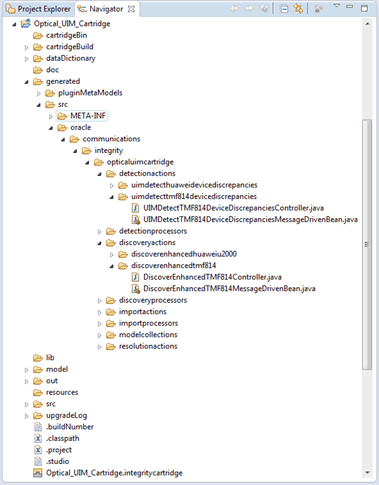
The generated Action MDB and controller classes can be found at the following directory:
Studio_Workspace\NI_Project_Root\generated\src\Project_Default_Package\Action_Type\Action_Implementation_Prefix
where the elements on the path are defined as follows:
-
Studio_Workspace: Eclipse Workspace root
-
NI_Project_Root: Network Integrity project root
-
Project_Default_Package: The default package configured in the Project editor
-
Action_Type: Select from the available action types:
-
assimilationactions
-
detectionactions
-
discoveryactions
-
importactions
-
resolutionactions
-
-
Action_Implementation_Prefix: action implementation prefix in lowercase.
The generated MDB class is named: ActionNameMessageDrivenBean.java.
The generated controller class is named ActionNameMessageDrivenBeanController.java.
During design time, compilation errors or warnings against this Java class might occur. These errors and warnings are cleared after properly implementing and configuring the action (and its processors).
Figure 2-2 shows the directory that contains the generated MDB and controller classes.
About Scan Parameter Groups
Scan parameter groups are a special type of specification that adds fields to the Network Integrity UI. You can add fields to the Create Scan page, allowing the Network Integrity user to pass scan parameter values to run-time scans. You can add fields to the Scan Details page, displaying the configured scan parameter values on configured scans.
Add and configure characteristics on scan parameter groups to create input fields for scan parameters in the Network Integrity UI.
You can add scan parameter groups to the following types of actions:
-
Assimilation actions
-
Discovery actions
-
Import actions
See the Design Studio Modeling Network Integrity Help for more information about creating and configuring scan parameter groups.
Extending the Create Scan Page
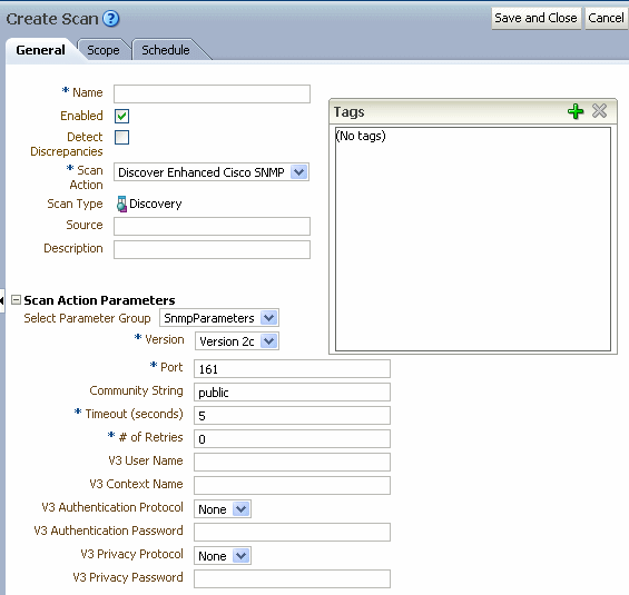
In Design Studio, you can configure characteristics on scan parameter groups to appear as input fields on the Create Scan page of the Network Integrity UI. These input fields allow the Network Integrity user to pass scan parameters to run-time scans.
For example, if a network device requires a login and password for Network Integrity to establish a connection, you can add input fields for the user name and password to the Create Scan page. Network Integrity users can enter the user name and password and save the values to the scan. Each scan run passes the user name and password parameter values to the network device to establish a connection.
See the Design Studio Modeling Network Integrity Help for more information about adding and configuring characteristics on scan parameter groups.
Figure 2-3 shows the Create Scans page. The Scan Action Parameters section lists all the input fields defined by characteristics on scan parameter groups in Design Studio.
Extending the Scan Details Page
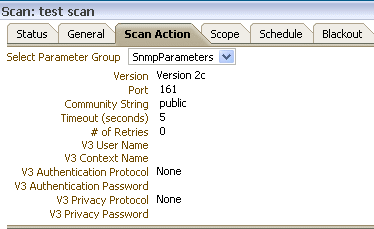
In Design Studio, you can configure characteristics on scan parameter groups to appear as read-only fields on the Scan Details page of the Network Integrity UI. These fields display the saved scan parameter values on the scan.
See the Design Studio Modeling Network Integrity Help for more information about adding and configuring characteristics on scan parameter groups.
Figure 2-4 shows the Scan Details page.
About Conditions
Design Studio sets conditions for processors used in action executions in Network Integrity.
An action can contain conditions. By creating and applying conditions to processors, at run time you can dynamically control which processors should be executed inside an action based on the condition (whether true or false).Conditions are implemented as a Java class that implements the condition interface. Design Studio generates the code for the condition interface. You then implements the condition interface.Conditions can be applied to one or more processors. Conditions can be set to be either true or false. One processor can also have multiple conditions applied. In this case, the processor are executed if all the conditions are true
See the Design Studio Modeling Network Integrity Help for more information about creating conditions and applying them to processors.
About Generated Classes and the Implementation Class
When a condition is configured for an action, Design Studio generates two classes:
-
Condition interface, which takes the name ConditionName_Implementation_PrefixCondition.java
-
Request, which takes the name ConditionName_Implementation_PrefixRequest.java
The generated classes are available at:
Studio_Workspace\NI_Project_Root\generated\src\Project_Default_Package\Action_Type\Action_Implementation_Prefix
Note:
This directory also contains generated action MDB and controller classes.The following is a sample generated condition interface which defines one method, checkCondition. In this sample, ValidDeviceRequest is the generated request class for the condition:
public interface ValidDeviceCondition {

   /**
    * @param context
    * @param request
    * @return @see boolean
    * @throws ProcessorException
    */
  public boolean checkCondition(DiscoveryProcessorContext context,
             ValidDeviceRequest request) throws ProcessorException;
}
Design Studio also generates the skeleton implementation class for this condition interface. To open the Java editor and start the Java implementation, click the Implementation Class link.
Adding Dependent Actions with Conditions as Processors
When you add an action from a dependent cartridge project, the action comes with its conditions. The conditions cannot be removed from any processors to which they are applied in the dependent cartridge project.
You can add and remove additional conditions to processors belonging to actions from dependent cartridge projects.
By adding new conditions to dependent action processors, you can change whether an imported processor is executed.
About Model Collections in Actions
Use model collections to gather specifications from other, dependent cartridges and make them available to actions in the current cartridge project.
Adding a model collection to an action enables the generation of the Specification Helper classes for specifications from other cartridge projects. These classes are by the action for modeling the discovered data into the Oracle Communications Information Model and persisting it using POMS entity managers.
If an action is imported into another action in a different cartridge project, the Network Integrity packager uses the model collections to determine how to build the specification DAO files so that all specifications (from both the imported action and the current action) are included.
See "About Model Collections" for more information about model collections.
About For Each Processors
An action can contain a For Each processor. The action controller sets the execution sequence of the processors based on the order in which the processors are configured. Usually a processor is invoked only once, and when it has executed, the controller invokes the next processor, until all processors in an action are invoked. However, one or more processors may be executed repeatedly. For example, when importing an inventory system, it is typical to first get a list of devices from the inventory system, then go through the list of devices and import each device singly into Network Integrity. In this example, the processor importing a single device is repeatedly executed for all the devices in the returned device list. You can use For Each processors to create a loop, containing one or more processors, to repeatedly execute the processors. Design Studio for Network Integrity supports nested For Each processors.
A For Each processor expects a collection as the input parameter so that it can iterate through the collection and, for each object in the collection, invoke the processors inside the loop. There must be a preceding processor that outputs an array or a Java object that implements java.lang.Iterable (for example, java.util.List) as an output parameters to create a For Each processor.
See the Design Studio Modeling Network Integrity Help for more information about creating For Each processors.
About Result Categories
Result category is a mandatory field for the following action types:
-
Discovery action
-
Import action
-
Assimilation action
Result category is the identifier for a result group. An action configured with a result category persists the results to the corresponding result group after being deployed and executed in Network Integrity. The result category is visible in the Network Integrity UI when displaying the scan results.
Figure 2-5 shows the result category in the Network Integrity UI. The discovered device is stored under the result category, Device.
Tip:
Provide an appropriate result category when configuring an action, because this value is displayed in the Network Integrity UI.Result categories identify a result group that an action adds the results to the result group. The result category value configured for the action must match the result group name in the Java implementation (the addToResult method) for the discovered data. See Network Integrity Information Model Reference for information about using result categories in modeling results.
For more information about this Java implementation, see "Working with Processors".
Design Studio does not explicitly validate this result category name against the actual result group name specified in the Java implementation.
The result category and action define a result source for the following action types:
-
Discrepancy detection action
-
Discrepancy resolution action
Both actions work on results (to perform discrepancy detection or resolution, respectively) based on the result source.
For example, a discovery action persists discovered data in two result categories:
-
Device
-
Workstation
A discrepancy detection action works on discovered data stored in the result categories that match the result groups in the Java implementation. If the result category configured for the discovery action does not match the actual result group name in the Java implementation, but the discovery detection action is configured with the result source based on the result category configured in Design Studio, the discrepancy detection action is not able to find the results to perform discrepancy detection at run time. In other words the result group name does not match the result category defined in result source.
About Import Actions
Import actions are used to import data from an inventory system into Network Integrity. The data is stored in the Oracle Communications Information Model representation and is flagged as having come from the inventory system. The Network Integrity GUI displays and reports on the data discovered by an import action. The data can also subsequently be processed by discrepancy actions that compare network-discovered data to inventory-discovered data, and reports differences between them.
Import actions are edited in Design Studio. As a result of the editing, Design Studio generates most of the required deployment artifacts. However, you must supply some Java implementation. After this is done, and all error problems are cleared, and if the import action is not abstract, Design Studio automatically packages the action into a cartridge Integrity ARtifact (IAR) file that can be easily deployed into the Network Integrity server. Then, on the Network Integrity server, an import scan can be created and executed, and the scan results viewed or reported on.
See the Design Studio Modeling Network Integrity Help for more information about creating and configuring import actions and processors.
See "Implementing an Import Processor" for more information.
About Discovery Actions
The discovery action discovers data, typically from the network, and persists it to the Oracle Communications Information Model. The discovery action accesses the network using a variety of technologies and protocols, such as simple network management protocol (SNMP).
Because SNMP is such an important protocol for network discovery, Network Integrity provides specific features to allow streamlined development of SNMP network discovery cartridges within Design Studio for Network Integrity. See "Implementing the SNMP Processor" for more information.
See "Implementing a Discovery Processor" for more information.
See the Design Studio Modeling Network Integrity Help for more information about creating and configuring discovery actions and processors.
About Discovery Action Address Handlers
Discovery scans are often used to scan multiple devices in the network. A discovery scan can use a variety of protocols to perform a scan. To facilitate scan processing, Network Integrity supports an address expansion and validation software component called an address handler. Address handlers perform two functions:
-
They validate that a user-supplied address string is syntactically correct for a protocol.
-
They expand address strings which represent multiple addresses, into a collection of individual addresses.
This allows the user to configure a scan of multiple addresses using a compact, efficient notation; for example: the notation 10.156.67.1-254 expresses the range of addresses from 10.156.67.1 to 10.156.67.254, which is 254 addresses.
Discovery actions can optionally specify an address handler to use. It is best practice to create an address handler whenever address validation is desired. Addresses are validated when a scan configuration for the discovery action is saved, and also when the scan is run.
In addition, address strings representing multiple addresses are expanded into a collection of addresses when the scan runs. When an address string is expanded into multiple addresses, Network Integrity calls into the discovery action multiple times until each individual address has been scanned. The scanning of multiple addresses is done in parallel.
Address handlers are created in Design Studio for Network Integrity. Design Studio for Network Integrity generates some artifacts for the address handlers. However, you should supply implementation code to complete the address handler.
Address handlers become stateless session beans in the run-time environment. Cartridge projects containing address handlers must be deployed before any cartridge project that uses the address handlers are deployed.
Note:
Address handlers cannot be created in the same cartridge project as actions. To add address handlers to actions, you must make the cartridge project that contains the actions dependent on the project that contains the address handlers.You can download the and import the Address_Handler cartridge project which contains several basic address handlers. See "About the Address_Handlers Cartridge" for more information.
See the Design Studio Modeling Network Integrity Help for information about creating address handlers.
About the Address_Handlers Cartridge
Network Integrity provides the Address_Handlers cartridge which implements the following address handlers:
-
IPAddressHandler validates and expands both IPv4 and IPv6 address.
It validates and expands the following IP address formats:
-
Single IP addresses; for example: 10.156.67.123
-
IP address ranges using ”-”; for example: 10.156.67.10-125
-
IP address ranges using ”*”; for example: 10.156.67.*, equal to 10.156.67.0-255
-
IP addresses using Classless Inter-Domain Routing (CIDR); for example: 10.156.67.0/24
-
-
URLAddressHandler validates URL syntax addresses.
-
File TransferAddressHandler validates addresses and paths used by the file transfer processor, as follows.
-
Allows the field to contain one or two tokens delimited by "/"
-
Using a single token identifies:
-
The absolute path to files that are local to the Network Integrity server, for example: /tmp
-
-
Using two tokens identifies:
-
The remote location and absolute path
-
Host_name/path, for example: someserver.us.com/tmp/test
-
IPV4Address/path, for example: 10.156.58.63/tmp/test
-
IPV6Address/path
-
-
Validates the proper format of IPV4 and IPV6Address
-
Note:
The file transfer processor does not support address expansion and relative paths.-
Corba URLAddressHandler validates that the address entered in Network Integrity is a properly formatted IPv4 or IPv6 CorbaLoc URL. For more information, see Network Integrity CORBA Cartridge Guide.
Implementing Address Handlers
You must specify the implementation class for an address handler. See the Design Studio Modeling Network Integrity Help for more information.
About the AddressHandler Interface
Address handlers must implement the AddressHandler interface which is shown and described in the following section:
package oracle.communications.integrity.api;

import java.util.List;
import oracle.communications.integrity.common.AddressHandlerException;
import oracle.communications.integrity.common.AddressesStatus;

/**
 * AddressHandler is common interface which should be implemented by the
 * class implementing the Address expansion and validation of addresses.
 */
public interface AddressHandler {

    /**
     * This method expands the list of address or addressRange provided.
     * @param addressRangeList - a list of String representing either an address or an address range
     * @return List - a list of Strings each of which represents an individual address
     * @throws AddressHandlerException
     */
     public List<String> expandAddressRange(List<String> addressRangeList) throws AddressHandlerException;

    /**
     * This method validates the list of address provided.
     * @param address
     * @return AddressesStatus
     * @throws AddressHandlerException
     */
     public AddressesStatus validate(List<String> address) throws AddressHandlerException;

     /**
     * This method validates the single address provided.
     * @param address
     * @return boolean
     * @throws AddressHandlerException
     */
     public boolean validate(String address) throws AddressHandlerException;

     /**
     * This method counts the number of addresses after expansion of address parameter passed.
     * Here maxCountLimit can be NULL. If maxCountLimit is NULL, method return the total count of expanded address.
     * If maxCountLimit is specified, method does not count the expanded address
     * beyound that limit and returns the maxCountLimit + 1.
     * @param addressRangeList
     * @param maxCountLimit
     * @return int
     * @throws AddressHandlerException
     */
     public int countExpandedAddresses(List<String> addressRangeList, Integer maxCountLimit) throws AddressHandlerException;
}
About Dynamic Address Handlers
When you configure a Network Integrity discovery scan, you specify one or more addresses as the scope for the discovery scan.
The discovery scan scope can point to one or more addresses.
When the network changes, you likely need to modify the discovery scope to add or remove addresses.
You can create an address handler that references a file at run time, dynamically populating the discovery scan scope.
See the Design Studio Modeling Network Integrity Help for information about creating an address handler.
The following sections explain how to implement a dynamic address handler.
Validating the Address Handler
Validation methods are invoked to validate user-entered addresses. In this sample, an address is expected to be a path to a file (absolute, or relative to the WebLogic Server Network Integrity domain). This validation method checks each address, and the result indicates which addresses (if any) are not valid:
@Override
public boolean validate(String address) throws AddressHandlerException {
  File file = new File(address);
  if (!file.exists() || !file.isFile()) {
    return false;
  }
  return true;
}
You must also implement a list variant of the validation method without additional validation logic. The following sample shows the method for implementing a list variant.
@Override
public AddressesStatus validate(List<String> addresses)
    throws AddressHandlerException {
  AddressesStatus result = new AddressesStatus();
  for (String address : addresses) {
    if (!validate(address)) {
      result.getInvalidAddressList().add(address);
    }
  }
  result.setAllAddressValid(result.getInvalidAddressList().isEmpty());
    return result;
}
When you run a scan, the address handler invokes address expansion methods to derive individual address from ranges of addresses.
The expandAddressRange method takes the addresses (as entered on the Scope tab) and returns a list of expanded addresses.
The file is read line by line and the following logic is applied:
-
Remove leading and trailing white space
-
Ignore empty lines
-
Ignore comments (starting with #)
-
When a line starts with $, it indicates a malformed address and the address expansion fails.
The explicit validate method is not invoked for expanded addresses.
The use of a LinkedHashSet avoids issues with duplicate addresses in the file, while still preserving the order. In this sample, each input address references a file.
@Override
public List<String> expandAddressRange(List<String> addresses)
    throws AddressHandlerException {
  Set<String> expandedAddresses = new LinkedHashSet<String>();
  for (String address : addresses) {
    expandedAddresses.addAll(readAddressesFromFile(address));
  }
  return new ArrayList(expandedAddresses);
}
public List<String> readAddressesFromFile(String path)
    throws AddressHandlerException {
  try {
    BufferedReader reader = new BufferedReader(new FileReader(path));
    try {
      List<String> addresses = new ArrayList<String>();
      String address = null;
      while ((address = reader.readLine()) != null) {
        // ignore blank lines, and comment lines (starting with #)
        address = address.trim();
        if (! address.isEmpty() && ! address.startsWith("#")) {
          // Address validation applies only to addresses entered as Scope for scan. In this example, further validation may be of interest in case file content is malformed. This illustrates how to reject an illegal dynamic address
          if (address.startsWith("$")) {
            throw new AddressHandlerException("Illegal address \"" + address + "\" found in file \"" + path + "\"");
          }
          addresses.add(address);
        }
      }
      return addresses;
    } finally {
  reader.close();
  }
} catch (IOException ex) {
  throw new AddressHandlerException("Unable to read addresses from file \"" + path + "\"", ex);
  }
}
The following sample shows a method that returns the count of the expanded addresses. For certain types of address handlers, counting is more efficient than expansion. For example, a /24 IP address range is 256 addresses. In this sample, addresses are expanded and counted.
@Override
public int countExpandedAddresses(List<String> addresses, Integer maxCount)
    throws AddressHandlerException {
  return expandAddressRange(addresses).size();
}
Testing the Dynamic Address Handler
To test a dynamic address handler, create a discovery action in Design Studio that uses the dynamic address handler you implemented. See the Design Studio Modeling Network Integrity Help for information about creating actions.
To test the dynamic address handler:
-
Deploy the cartridge containing the dynamic address handler and the discovery action.
-
Create an address.txt address file that is accessible to the application server. The file is created in the Weblogic domain home directory with the following content:
Some Address
Another Address
Address 3
-
In Network Integrity UI, create a scan and select the discovery action you created.
-
In the Scope tab, specify the addresses.txt file.
-
Run the scan.
-
On the Scan Results page, click Display Addresses to see the expanded addresses that were read from the file.
-
Edit the addresses.txt file and change the last address:
Some Address
Another Address
New Address
-
Run the scan again and view the addresses to see the new addresses that were read from the file.
About Discovery Action Result Categories
A discovery action must be configured with a valid result category. For example, a discovery action that discovers devices should be configured with the Device result category.
See "About Result Categories" for more information.
See the Design Studio Modeling Network Integrity Help for more information about adding a result category to a discovery action.
About the Discovery Action in the Network Integrity UI
After successfully building a discovery action in Design Studio (see "Building and Packaging Projects"), deploy the cartridge to Network Integrity (see "Deploying and Undeploying Cartridges").
When the cartridge containing the discovery action is successfully deployed to Network Integrity, log on to the Network Integrity UI and configure a scan using the deployed discovery action.
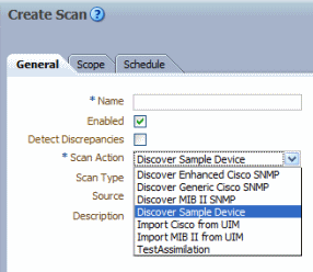
The recently deployed discovery action is available in the Scan Action list when creating a scan configuration. See the Network Integrity Help for more information about creating a scan.
Figure 2-6 displays a discovery action called Discover Sample Device.
About Discovery Action Scan Parameter Groups
You can configure scan parameter groups for a discovery action. Add characteristics to scan parameter groups to appear in the Network Integrity UI as scan parameters. For example, consider the following scan parameters:
-
Port: The port number that a discovery command is sent to
-
Username: The user name to make the connection
-
Password: The password to make the connection
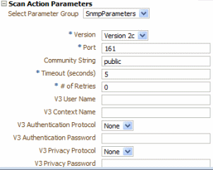
When a scan is created using Discover Sample Device (see "About the Discovery Action in the Network Integrity UI"), the Scan Action Parameters section on the Create Scan page is filled with SNMP scan parameters.
Figure 2-7 displays the Scan Action Parameters area with SNMP scan parameters configured.
To make configuration items available in the Network Integrity UI, add and configure characteristics on scan parameter groups. See the Design Studio Modeling Network Integrity Help for more information.
See "About Scan Parameter Groups" for more information.
About Assimilation Actions
Assimilation actions perform additional processing on existing Network Integrity network data to derive additional, often higher level, information from the data. For example, an assimilation action might be used to derive connectivity relationships between endpoints discovered by previous scans. Assimilation actions cannot manipulate or edit scan results.
Assimilation scans are different from other types of scans in that they do not retrieve their data from external sources. Instead, assimilation scans work on the scan results of other discovery, import, or assimilation scans. When you run an assimilation scan, the scan selects other scans as inputs to the assimilation scan in the Scope page of the Network Integrity GUI. You can select discovery, import, or other assimilation scans as input.As with other scan types, the data from assimilation actions is stored in the Oracle Communications Information Model representation. The data from assimilation scans is flagged as having come from the network. The Network Integrity GUI displays and reports on the data discovered by an assimilation action. The data can also subsequently be processed by discrepancy actions, which compare network discovered data to inventory discovered data and report where differences are found.
Assimilation actions are edited in Design Studio. As a result of the editing, Design Studio generates most of the required deployment artifacts. However, you must supply some Java implementation. After this is done, and all error problems are cleared, and if the assimilation action is not abstract, Design Studio automatically packages the action into a cartridge Integrity ARtifact (IAR) file, which can be easily deployed into the Network Integrity server. Then, on the Network Integrity server, an assimilation scan can be created and executed, and the scan results viewed or reported on.
See "Implementing an Assimilation Processor" for more information.
See the Design Studio Help for more information on creating assimilation actions and processors.
About Discrepancy Detection Actions
The discrepancy detection action is a Network Integrity operation that compares discovery and import scan results, and reports on their differences by generating discrepancies.
A discrepancy detection action can be run immediately following a discovery, import, or assimilation scan. (Select the Detect Discrepancy check box in the scan configuration to set the trigger.) The entity results from the triggering scan become the Compare entities for the detection action. The action then uses a matching algorithm to find from the other side, and precedes with the comparisons.
See "About the Compare and Reference Sides" for a fuller description of the two sides of entities of discrepancy detection.
See "About the Base Detection Project and the Default Comparison Algorithm" for a description of the comparison algorithm.
Create a discrepancy detection action whenever new discovery, import, or assimilation actions are created, because every detection action is configured to receive results from specific actions only. See "About Result Sources" for more information.
See "About Discrepancy Detection Processors" for more information.
See the Design Studio Modeling Network Integrity Help for more information about creating discrepancy detection actions and processors.
About Discrepancy Detection
Discrepancy detection triggers immediately after a scan is finished. A scan is configured to use a single type of action, and therefore only generates Discovery results (representing network entities) or Import results (representing inventory system entities). Therefore, when the discrepancy detection action triggers, it has immediate access to one side of results: the compare entities.
For the other side of the results, the detection action searches the Network Integrity database for results with the following criteria:
-
The results must come from the opposite system from the triggered scan. For example, if the detection action triggers from a discovery scan, then the detection action searches the database for Import result.
-
The results have a matching name and result category (as configured by result source).
-
The results must come from the most recent scan result.
If no matching results are found, then EXTRA_ENTITY discrepancies are generated for each root entity on that result.
About Result Sources
A result source specifies a list of scan actions that can trigger a discrepancy detection action. The triggering action must be a discovery, import, or assimilation action. By default, results from all categories are included in the discrepancy detection. It is possible to choose a subset of the categories to apply the discrepancy detection.
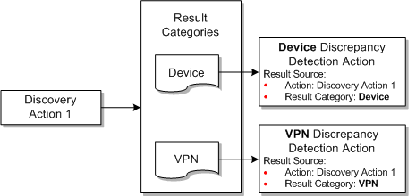
For example, Figure 2-8 illustrates a Cisco router discovery action that produces results in 2 categories: Device and VPN. Two separate detection actions are written to compare the results. Each detection action specifies a result source with the same action, but different result category. For example, the device discrepancy detection action receives results of Device category only.
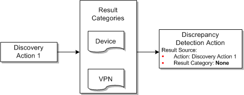
A result source that does not specify a result category matches every result category generated by the scan action. Figure 2-9 illustrates a Cisco discrepancy detection action that receives both device and VPN categories of results.
The result source is a mandatory field; there must be at least one entry in the table. Design Studio marks the discrepancy detection action with an error during a project build if the table has no entries.
Note:
No two discrepancy detection actions can have the same result source.About Result Source and Scan Types
Typically a result source configuration detection action has a single action as the result source: usually the discovery action. This detection action triggers when a scan is configured using that exact discovery action, and the Detect Discrepancy option is checked. This detection action does not trigger by scans configured with any other discovery or import action. Do not set the Detect Discrepancy option on the Import scan, because this might not trigger a detection action at all.
Generated Action MDB and Controller
The detection action is implemented as an MDB. See "About the Generated Action MDB and Controller" for more information.
About Discrepancy Resolution Actions
A discrepancy resolution action is an extendable Network Integrity operation which acts on an external system to resolve a discrepancy. For example, a resolution action updates a mismatch in an inventory system using information gathered from the network or generates a trouble ticket to kick off a network configuration change process.
A discrepancy resolution action operation is initiated by the Network Integrity user on the Manage Discrepancy page, using the following steps:
-
The user identifies the desired resolution action on selected discrepancies. Each discrepancy can have only one resolution action set.
-
The user submits the discrepancies with identified resolution actions to the system.
On receiving the submitted discrepancies, Network Integrity groups them based on their scan origin, result category, and resolution label, and then invokes the appropriate discrepancy resolution action.
The action then examines each discrepancy in detail, using the contained information to figure out the appropriate steps to resolve the problem.
As with other types of actions, a discrepancy resolution action is made up of a sequence of discrepancy resolution processors. The processors are shown in the Processor table in Design Studio. At the beginning of an action operation, these processors are invoked serially from top of the table to bottom. The first processor is given the list of submitted discrepancies marked. This processor determines a subset of these discrepancies to handle (which can range from none to all), performs the resolution operation, and sets their status to Processed or Failed. Then, the next processor is given the remaining discrepancies for processing, and so on.
The action is complete when all the processors are invoked. If there are any discrepancies which remain unhandled at the end, their status is automatically set to Not Implemented.
The following sections in this chapter describe general information about implementing a resolution action. For a detailed discussion of a working sample, see the following documents included with the cartridges:
-
Network Integrity Cisco Router and Switch UIM Integration Cartridge Guide
-
Network Integrity MIB-II UIM Integration Cartridge Guide
See "About Discrepancy Resolution Processors" for more information.
See the Design Studio Modeling Network Integrity Help for more information about creating discrepancy resolution actions and processors.
About the Resolution Action Label
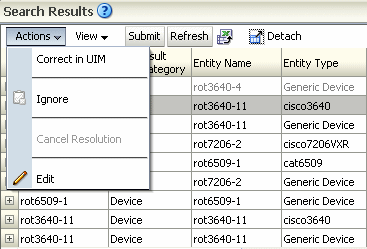
The Resolution Action Label identifies the discrepancy resolution action in the Network Integrity UI. It is displayed as a command in the Actions menu of the Discrepancy Search Results table of the Review Discrepancies page.
Figure 2-10 displays the label corresponding to the command.
This label is a mandatory field. Design Studio reports an error if this label has no value. The use of a command phrase as the label string is recommended. Some example labels are:
-
Correct in Inventory System
-
Open a Trouble Ticket
The label input field allows you to choose either a label from another discrepancy resolution action defined within your workspace, or to type in a new label. A label can be shared by multiple actions; this implies that multiple actions are sharing a single menu item in the Actions menu of the Discrepancies page.
Network Integrity determines the correct action to invoke based on a combination of the label and the result source.
Note:
No two discrepancy resolution actions can have the same label and the same result source.About Result Sources
The result source is a list of discrepancy filtering criteria. Each criterion represents a single source of discrepancy, and is specified by a combination of the originating scan action and a result category. A resolution action only receives discrepancies from the specified result categories which were created by scans using the specified actions.
Figure 2-11 shows an example of result sources being applied in Network Integrity.
A criterion that does not specify any result category matches all result categories generated by the scan action in the criterion.
Figure 2-12 shows a representation of the discrepancy types.
The result source is a mandatory field; there must be at least one entry in the table. Design Studio marks a discrepancy resolution action with an error during a project build if this table has no entries.
Note:
No two discrepancy resolution actions can have the same label and the same result source.Generated Action and MDB Controller
The discrepancy resolution action is implemented as an MDB, just like any other Network Integrity action.
See "About the Generated Action MDB and Controller" for more information.

