2 About the Cartridge Components
This chapter provides information about the components of the Oracle Communications Network Integrity Optical UIM Integration cartridge.
The Optical UIM Integration cartridge contains the following actions:
Discover Enhanced Huawei U2000 Action
The Discover Enhanced Huawei U2000 action discovers logical device hierarchies and models them as Network Device model hierarchies. This discovery action also remodels the physical device hierarchy into a Huawei OptiX OSN 3500 physical device hierarchy by changing the specification on the equipment objects from TMF814 specifications to Huawei OptiX OSN specifications. When a Huawei specification is not found during remodeling, the original specification is retained.
This discovery action extends the Discover Huawei U2000 action (from the Optical TMF814 CORBA cartridge) and inherits all its processors. For information about the inherited processors in this action, see Network Integrity Optical TMF814 CORBA Cartridge Guide.
The Discover Enhanced Huawei U2000 action contains the following processors run in the following order:
-
CORBA Property Initializer (inherited)
-
TMF814 CORBA Property Initializer (inherited)
-
CORBA Connection Manager (inherited)
-
TMF814 Property Initializer (inherited)
-
TMF814 Property Customizer (inherited)
-
Huawei Customizer (inherited)
-
TMF814 Session Manager (inherited)
-
TMF814 Device Recorder Initializer (inherited)
-
TMF814 ME Collector (inherited)
-
TMF814 Device Modeler (inherited)
-
TMF814 Equipment Collector (inherited)
-
TMF814 Equipment Modeler (inherited)
-
TMF814 PTP Collector (inherited)
-
TMF814 PTP Modeler (inherited)
-
TMF814 CPT Discoverer for PTP (inherited)
-
Huawei MSTP EndPoint Collector (inherited)
-
Huawei MSTP EndPoint Modeler (inherited)
-
TMF814 FTP Collector (inherited)
-
TMF814 FTP Modeler (inherited)
-
TMF814 CTP Discoverer for FTP (inherited)
-
TMF814 Device Persister (inherited)
-
TMF814 Device Recorder Persister (inherited)
-
TMF814 Cross-Connect Discoverer (inherited)
-
TMF814 Topological Link Collector (inherited)
-
TMF814 Topological Link Modeler (inherited)
-
TMF814 Pipe Persister (inherited)
Figure 2-1 illustrates the processor workflow of the Discover Enhanced Huawei U2000 action.
Figure 2-1 Discover Enhanced Huawei U2000 Action Processor Workflow
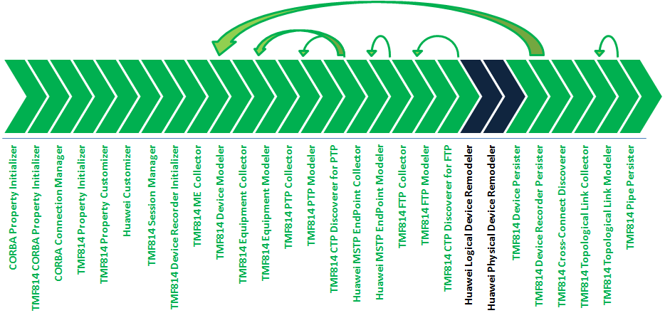
Description of ''Figure 2-1 Discover Enhanced Huawei U2000 Action Processor Workflow''
Huawei Logical Device Remodeler
This processor remodels the TMF814 discovery results into logical device hierarchies.
Huawei Physical Device Remodeler
This processor remodels the physical device hierarchy into a Huawei OptiX OSN 3500 physical device model.
If the device model is an OptiX OSN 3500 device, this processor calls the HuaweiOptiXOSN3500Remodeler class.
If the device model is not an OptiX OSN 3500 device, this processor does not remodel the physical device hierarchy.
You can add other Huawei device remodeler classes into the remodeler when the remodel class is specific to the device.
The following example shows the changes that are made when the HuaweiOptiXOSN3500Remodeler class is called. This flow is used to remodel the physical devices returned by the TMF814 discovery processors.
For each shelf {
  replace specification
  For each slot {
    replace specification
    For each card {
      replace specification
      For each port {
        replace specification
      }
    }
  }
}
Discover Enhanced TMF814 Action
The Discover Enhanced TMF814 action discovers logical device hierarchies and remodels them as Network Device model hierarchies.
This discovery action extends the Discover TMF814 action (from the Optical TMF814 CORBA cartridge) and inherits all its processors. For information about the inherited processors in this action, see Network Integrity Optical TMF814 CORBA Cartridge Guide.
The Discover Enhanced TMF814 action contains the following processors run in the following order:
-
CORBA Property Initializer (inherited)
-
TMF814 CORBA Property Initializer (inherited)
-
CORBA Connection Manager (inherited)
-
TMF814 Property Initializer (inherited)
-
TMF814 Property Customizer (inherited)
-
TMF814 Session Manager (inherited)
-
TMF814 Device Recorder Initializer (inherited)
-
TMF814 ME Collector (inherited)
-
TMF814 Device Modeler (inherited)
-
TMF814 Equipment Collector (inherited)
-
TMF814 Equipment Modeler (inherited)
-
TMF814 PTP Collector (inherited)
-
TMF814 PTP Modeler (inherited)
-
TMF814 CPT Discoverer for PTP (inherited)
-
TMF814 FTP Collector (inherited)
-
TMF814 FTP Modeler (inherited)
-
TMF814 CTP Discoverer for FTP (inherited)
-
TMF814 Device Persister (inherited)
-
TMF814 Device Recorder Persister (inherited)
-
TMF814 Cross-Connect Discoverer (inherited)
-
TMF814 Topological Link Collector (inherited)
-
TMF814 Topological Link Modeler (inherited)
-
TMF814 Pipe Persister (inherited)
Figure 2-2 illustrates the processor workflow of the Discover Enhanced TMF814 action.
Figure 2-2 Discover Enhanced TMF814 Action Processor Workflow
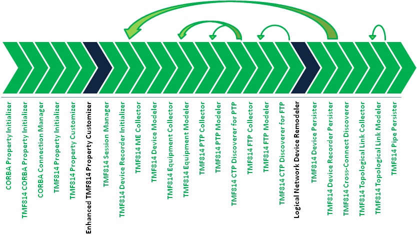
Description of ''Figure 2-2 Discover Enhanced TMF814 Action Processor Workflow''
Enhanced TMF814 Property Customizer
This processor sets the modeler processors to model only the logical device tree and not to model the physical device tree.
Logical Network Device Remodeler
This processor remodels the logical device hierarchies from the TMF814 discovery results. This processor removes the TMF814 TPLayer Generic objects from the logical device tree from each DeviceInterface entity and then remaps specifications and attributes. This processor also corrects VC3/VC12 layers.
Assimilate Huawei Optical Circuits Action
The Assimilate Huawei Optical Circuits action assimilates the results from the Discover Enhanced Huawei U2000 action and forms end-to-end synchronous digital hierarchy (SDH) circuits.
This assimilation action extends the Assimilate Optical Circuits action (from the Optical Circuit Assimilation cartridge) and inherits all its processors. For information about the inherited processors, see Network Integrity Optical Circuit Assimilation Cartridge Guide.
The Assimilate Huawei Optical Circuits action contains the following processors run in the following order:
-
Layer Rate Initializer (inherited)
-
Optical Assimilation Initializer (inherited)
-
Optical VC4 HOT HOP Assimilator (inherited)
-
Optical VC3 LOT LOP Assimilator (inherited)
-
Optical VC12 LOT LOP Assimilator (inherited)
-
Optical Assimilation Circuit Matcher (inherited)
-
Page Initialization for Circuit (inherited)
-
Optical Assimilation Modeler (inherited)
-
Optical Assimilation Persister (inherited)
-
Link Modeler (inherited)
-
Link Persister (inherited)
-
Cleanup Processor (inherited)
Figure 2-3 illustrates the processor workflow of the Assimilate Huawei Optical Circuits action.
Figure 2-3 Assimilate Huawei Optical Circuits Action Processor Workflow
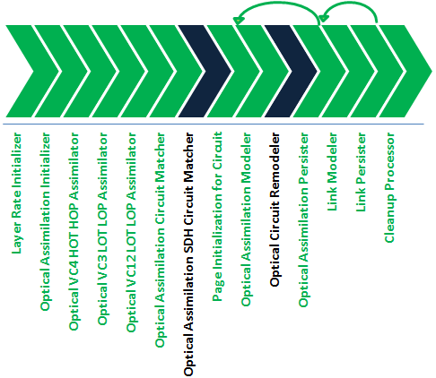
Description of ''Figure 2-3 Assimilate Huawei Optical Circuits Action Processor Workflow''
Optical Assimilation SDH Circuit Matcher
This processor matches assimilated data with your inventory system. Cross-connect and topological link object naming can often vary over a network. When this processor matches an assimilated circuit with an inventory circuit, it applies the inventory circuit name to the assimilated circuit.
The Assimilate Huawei Optical Circuits action is configured with the IsUIMHuaweiOpticalCircuit condition. When this condition is met, this processor is run and the inherited Optical Assimilation Circuit Matcher processor is not run.
This processor has the same functionality as the Optical Assimilation Circuit Matcher processor, but also contains logic to collect and model partially-protected circuits in the UIM model.
Optical Circuit Remodeler
This processor combines pipes to form complete paths for partially-protected circuits. This processor operates on both transport paths and circuit trail paths.
Import Logical Optical from UIM Action
The Import Logical Optical from UIM scan imports logical optical data entities from UIM and models them in the Network Logical Device Model. Also, this import action provides extensibility for features specific to SDH that you want to add.
Table 2-1 lists the values that are used when configuring the filters in the base class.
| Filter | Value |
|---|---|
|
Query Physical Devices |
False |
|
Import Related Physical or Logical Device |
False |
|
Logical Device Specification |
Network Device |
This import action extends the Abstract Import from UIM action (from the UIM Integration cartridge) and inherits all its processors. For information about the processors inherited from the Abstract Import from UIM action, see Network Integrity UIM Integration Cartridge Guide.
The Import Logical Optical from UIM action contains the following processors run in the following order:
-
Import UIM Initializer (inherited)
-
Logical Device UIM Finder (inherited)
-
Physical Device UIM Finder (inherited)
-
Logical Device UIM Importer (inherited)
-
Linked Physical Device UIM Importer (inherited)
-
Logical Device UIM Persister (inherited)
-
Physical Device UIM Importer (inherited)
-
Physical Device UIM Persister (inherited)
Figure 2-4 illustrates the processor workflow of the Import Logical Optical from UIM action.
Figure 2-4 Import Logical Optical from UIM Action Processor Workflow
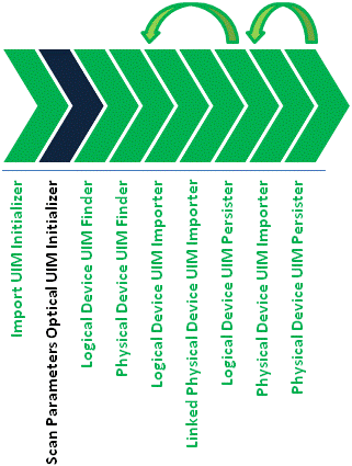
Description of ''Figure 2-4 Import Logical Optical from UIM Action Processor Workflow''
Scan Parameters Optical UIM Initializer
This processor initializes the scan parameters configured by the Network Integrity user.
Import Optical from UIM Action
The Import Optical from UIM action imports physical devices, logical devices, and channelized connectivities from UIM. Channelized connectivities are modeled into the Network Integrity Model according to their rate code. For example, synchronous transport module (STM) connectivities are modeled as topological links; VC4 connectivities are modeled as transport circuits; E1, E3, and E4 connectivities are modeled as customer circuits. See Network Integrity Information Model Reference for more information on the Network Integrity model.
For each channelized connectivity, only the most recent design version with a status of COMPLETED is imported.
The Optical UIM Import Parameters scan parameter group allows Network Integrity users to specify the scope of the import scan at run time:
-
Equipment only: imports physical and logical devices
-
Equipment and STM Links only: imports physical and logical devices and their channelized connectivities (topological links)
-
Equipment, STM Links, and Circuits: imports physical and logical devices and their channelized connectivities (topological links) and TDM facilities and connectivity trails
This import action extends the Abstract Import from UIM action (from the UIM Integration cartridge) and inherits all its processors. For information about the processors inherited from the Abstract Import from UIM action, see Network Integrity UIM Integration Cartridge Guide.
The Import Optical from UIM action contains the following processors run in the following order:
-
Import UIM Initializer (inherited)
-
Logical Device UIM Finder (inherited)
-
Physical Device UIM Finder (inherited)
-
Logical Device UIM Importer (inherited)
-
Linked Physical Device UIM Importer (inherited)
-
Logical Device UIM Persister (inherited)
-
Physical Device UIM Importer (inherited)
-
Physical Device UIM Persister (inherited)
Figure 2-5 illustrates the processor workflow of the Import Optical from UIM action.
Figure 2-5 Import Optical from UIM Action Processor Workflow
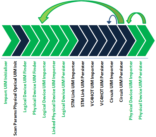
Description of ''Figure 2-5 Import Optical from UIM Action Processor Workflow''
Scan Params Physical Optical UIM Init
This processor initializes the scan parameters configured by the Network Integrity user.
STM Link UIM Importer
This processor imports channelized connectivities with the STM rate code for each logical device.
STM Link UIM Persister
This processor takes each STM channelized connectivity and models it in the Optical Model as an optical link. The modeled connectivities are then saved to the device result category.
VC4HOT UIM Importer
This processor imports channelized connectivities with the VC4 rate code for each logical device.
VC4HOT UIM Persister
This processor takes each VC4 channelized connectivity and models it in the Optical Model as a VC4 HOT transport circuit. The modeled connectivities are then saved to the device result category.
Circuit UIM Importer
This processor imports E1, E3, and E4 rate code channelized connectivities from UIM for each logical device. When the circuit originates on one device and terminates on another, the circuit is made the child of the first device in alphabetical order.
Circuit UIM Persister
This processor takes each channelized connectivity and models it in the Optical Model as a circuit. The modeled circuits are then saved to the device result category.
Circuits with one path are modeled as primary path circuits. Circuits with multiple paths are modeled with numbered path values (for example, path 1, path 2, path 3, and so on).
UIM Detect Huawei Device Discrepancies Action
The UIM Detect Huawei Device Discrepancies action detects device-level physical and logical discrepancies while filtering and removing unused attributes and characteristics from the logical and physical device models.
This discrepancy detection action extends the Abstract Detect UIM Discrepancies action (from the Network Integrity UIM Integration cartridge) and inherits all its processors. For information about the processors inherited from the Abstract Detect UIM Discrepancies action, see Network Integrity UIM Integration Cartridge Guide.
This action also extends the Auto Resolve Discrepancies action (from the NetworkIntegritySDK cartridge) to provide automatic discrepancy resolution. For information about the processors inherited from the Auto Resolve Discrepancies action, see Network Integrity Developer's Guide.
The UIM Detect Huawei Device Discrepancies action contains the following processors run in the following order:
-
UIM Discrepancies Filter Initializer (inherited)
-
Discrepancy Detector (inherited)
-
Check Auto Resolution Selected (inherited)
-
Identify Auto Resolving Discrepancies (inherited)
-
Prepare Resolving Discrepancies (inherited)
Figure 2-6 illustrates the processor workflow of the UIM Detect Huawei Device Discrepancies action.
Figure 2-6 UIM Detect Huawei Device Discrepancies Action Processor Workflow
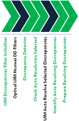
Description of ''Figure 2-6 UIM Detect Huawei Device Discrepancies Action Processor Workflow''
Optical UIM Huawei DD Filters
This processor applies filters to ignore the following types of discrepancies:
-
Missing equipment holder
-
Missing physical port
-
Missing physical device with a TMF814 specification
-
Missing equipment card with a TMF814 specification
-
Missing cross-connects
-
Missing topological links
UIM Auto Resolve Selected Discrepancies
This processor contains the automatic resolution Java class. The Java implementation class determines the types of discrepancies to be automatically resolved and the resolution logic.
See Network Integrity Developer's Guide for more information about completing the Java implementation class.
UIM Detect Optical Circuit Discrepancies Action
The UIM Detect Optical Circuit Discrepancies action detects discrepancies between assimilated circuits and imported channelized connectivities and circuits from UIM.
The name-matching logic compares assimilated circuit paths with imported circuit paths. When it finds a match, the name given during circuit assimilation is discarded and the imported circuit path name is used.
This discrepancy detection action extends the Abstract Optical Circuit Discrepancy Detection action (from the Network Integrity Optical Circuit Assimilation cartridge) and inherits all its processors. For information about the inherited processors in this action, see Network Integrity Optical Circuit Assimilation Cartridge Guide.
The UIM Detect Optical Circuit Discrepancies action contains the following processors run in the following order:
-
Circuit Discrepancy Name Filter Initializer (inherited)
-
Missing Entity Filter Initializer (inherited)
-
Discrepancy Detector (inherited)
Figure 2-7 illustrates the processor workflow of the UIM Detect Optical Circuit Discrepancies action.
Figure 2-7 UIM Detect Optical Circuit Discrepancies Action Processor Workflow
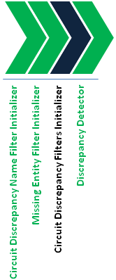
Description of ''Figure 2-7 UIM Detect Optical Circuit Discrepancies Action Processor Workflow''
Circuit Discrepancy Filters Initializer
This processor initializes the following discrepancy detection filters:
-
Attributes Filter: prevents discrepancy detection on the ID, physical location, description, rerouted, partial, sequence, aEnd, and zEnd attributes.
-
Channel Attribute Filter: changes the channel attribute mismatch discrepancy severity from minor to major.
-
Partial Circuit Filter: sets the status on partial circuit discrepancies to Ignore.
-
Ignore Container Level Discrepancy Filter: sets the status on container-level discrepancies to Ignore.
UIM Detect TMF814 Device Discrepancies Action
The UIM Detect TMF814 Device Discrepancies action detects discrepancies while filtering and removing unused attributes and characteristics from the logical and physical device models.
This discrepancy detection action extends the Abstract Detect UIM Discrepancies action (from the UIM Integration cartridge) and inherits all its processors. For information about the inherited processors in this action, see Network Integrity UIM Integration Cartridge Guide.
The UIM Detect TMF814 Device Discrepancies action contains the following processors run in the following order:
-
UIM Discrepancies Filter Initializer (inherited)
-
Discrepancy Detector (inherited)
Figure 2-8 illustrates the processor workflow of the UIM Detect TMF814 Device Discrepancies action.
Figure 2-8 UIM Detect TMF814 Device Discrepancies Action Processor Workflow
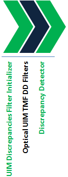
Description of ''Figure 2-8 UIM Detect TMF814 Device Discrepancies Action Processor Workflow''
Optical UIM TMF DD Filters
This processor applies filters to ignore the following types of discrepancies:
-
Missing device interface with a TMF814 specification
-
Media interface-specific attributes when comparing for connection termination points. For physical termination point interfaces, it compares as a media interface.
Resolve Optical in UIM Action
The Resolve Optical in UIM action resolves logical and physical device and circuit discrepancies between discovered data and the data imported from UIM.
For each channelized connectivity, only the most recent design version is resolved:
-
When the design status is IN_PROGRESS, this action updates the intermediate segment with network trail paths and sets the status to COMPLETED.
-
When the design status is COMPLETED or CANCELLED, this action creates a new intermediate segment using network trail paths and sets the status to COMPLETED.
-
For new entities, this action creates the first design versions and sets the status to COMPLETED.
This discrepancy resolution action cannot delete channelized connectivities from UIM when there exists multiple versions with the COMPLETED or CANCELLED status. Therefore, to resolve Missing Entity discrepancies on channelized connectivities, this discrepancy resolution action creates a new design version with a COMPLETED status and clears all intermediate segments.
This discrepancy resolution action extends the Abstract Resolve in UIM action (from the UIM Integration cartridge) and inherits all its processors. For information about the inherited processors in this action, see Network Integrity UIM Integration Cartridge Guide.
This action contains the following processors run in the following order:
-
UIM Resolution Framework Initializer
-
UIM Resolution Initializer
-
UIM Resolution Framework Dispatcher
Figure 2-9 illustrates the processor workflow of the Resolve Optical in UIM action.
Figure 2-9 Resolve Optical in UIM Action Processor Workflow
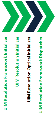
Description of ''Figure 2-9 Resolve Optical in UIM Action Processor Workflow''
UIM Resolution Optical Initializer
This processor initializes the following handlers to resolve discrepancies on channelized connectivities:
-
Pipe Termination Point Handler
-
Trail Path Handler
-
Entity Circuit Handler
About Recording Mode
You can configure the Optical UIM Integration cartridge to record all discovered managed elements (MEs), topological links, and cross-connects. The recorded files (ME_Name.me for MEs, EMS_Name.ems for topological links, and EMS_Name.cc for cross-connects) are saved to the Domain_Home/corbaData/Scan_Name/EMS_Name directory, where:
-
ME_Name is the name of the ME.
-
EMS_Name is the name of the element-management system (EMS).
-
Domain_Home is the Network Integrity WebLogic Server domain.
-
Scan_Name is the name of the scan.
If the TMF814 scan action type has been configured to not discover MEs, topological links, or cross-connects, the corresponding file is not generated.
The recording processor reads this file each time it is run.