2 Working with Control Flows
This chapter describes how to create and work with control flows to augment the services provided by the Volte and VoWifi application in Oracle Communications Evolved Communications Application Server (OCECAS).
For an introduction to the Session Design Center and an overview of control flows, see ”About the Session Design Center” in Oracle Communications Evolved Communications Application Server Concepts.
About the VoLTE and VoWiFi Application
The VoLTE and VoWiFi application provides session control and services for voice calls and multimedia sessions over Long Term Evolution (LTE) and for voice calls over WiFi. To define new services and behaviors for subscribers, you make changes to the VoLTE and VoWiFi application by creating or modifying control flows. You create and modify control flows in the context of a change set. For more information about change sets and change management, see "Working with Change Sets".
The VoLTE and VoWiFi application consists of four message control flows and five application control flows.
About the Message Control Flows
Message control flows are triggered when the application server receives one of the following SIP messages: HTTP DELETE, HTTP GET, HTTP POST, HTTP PUT, SIP INVITE, SIP OPTIONS, SIP REGISTER, or SIP SUBSCRIBE. Each of these messages triggers a control flow of the same name. For descriptions of these message control flows, see ”About Applications” in Oracle Communications Evolved Communications Application Server Concepts.
You can view the Message Control Flows by clicking View Application Configuration from the SDC home page and then clicking the name of the Message Control Flow that you want to view under the Application tab.
About the Application Control Flows
The VoLTE and VoWiFi Application control flows provide supplementary services and manage the phases of a session life cycle. The Session Origination and Session Termination control flows invoke additional control flows to deliver supplementary services. Supplementary services are services that supplement the telephony and data services.
The Session Deregistration control flow manages the life cycle of deregistration.
The Session Origination control flow manages the life cycle of the originating session. It executes additional control flows to invoke the following supplementary services:
-
Ad-hoc Conferencing - allows a subscriber to transform a one-to-one call session into a multi-party call session
-
Communication Hold Charging
-
Communication Hold (origination)
-
Originating Identity Restriction
-
Outgoing Communication Barring
-
Terminating Identity Presentation
The Session Registration control flow manages the life cycle of registration.
The Session Termination control flow manages the life cycle of the terminating session. It executes additional control flows to invoke these supplementary services:
-
Anonymous Communication Restriction
-
Communication Diversion
-
Communication Hold (termination)
-
Early Communication Diversion
-
Incoming Communication Barring
-
Originating Identity Presentation
-
Terminating Identity Restriction
The Terminating Access Domain Selection control flow selects the circuit-switched access or packet-switched access network(s) to use to deliver a terminating voice session to the user endpoint.
You can add Activities to the VoLTE, VoWiFi and eSRVCC session registration and de-registration control flows to perform specific tasks required by a customer in response to registration or de-registration events.
About Control Flow Activities
A session control flow consists of logically linked Activities, such as Start, Run Web Service, Start Charging Session, Start Conference Session, and so on. You must configure an Activity when you add it to a control flow.
Configuring an Activity consists of specifying values for the following elements:
-
Name
This is the Activity name, which can be the default name or a custom name that you assign. When you assign a custom name, the control flow editor retains the default name for internal use and displays it in smaller grey text.
-
Comments
You can add a short, optional comment to describe the Activity.
-
Parameters
An Activity can require a set of parameters for which you need to provide appropriate values.
All required parameters must be provided with values for the control flow to compile successfully.
-
Exits
Except for End, each Activity has one or more exits, which you must connect to the next logical action. All exits must have a connection for the control flow to compile successfully.
You can define dynamic exits for the Wait for Events Activity. A dynamic exit is one that you add to the Activity at the time you include the Activity in the control flow.
For a complete list with descriptions of the control flow Activities, including descriptions of their parameters and exits, see "Activities Reference".
About Using Control Flows
To define new services and behaviors for subscribers, you make changes to the VoLTE and VoWiFi application by creating or modifying control flows.A control flow consists of logically-linked actions (Activities) and decisions that specify how to process a voice call or multimedia session.
To understand the basic concepts of control flows, see "About the Session Design Center” in Oracle Communications Evolved Communications Application Server Concepts.
About the Control Flow Editor
When you open an existing control flow or create a new one, you open the control flow editor and the editing canvas. The editing canvas is the work area on which you create or edit the control flow logic. The canvas has vertical and horizontal scroll bars
The editing canvas also includes the following parts:
-
The Editing Toolbar
-
The Information panel
-
The Changes panel
About the Editing Toolbar
Table 2-1 lists the tool icons that can be found on the editing toolbar, which appears on the left side of the canvas:
Table 2-1 Editing Toolbar Icons
| Icon | Function |
|---|---|
|
Spyglass (search) |
Search the control flow. Clicking it opens an adjoining panel with a Search field followed by a list of control flows contained in the changed set. |
|
Pencil (edits) |
Shows control flow differences. Clicking opens a panel that details the differences between the current change set and the baseline change set. |
|
Circled Red Exclamation Point (warning) |
Shows issues found in this control flow. Clicking it opens a list of control flows having errors, along with descriptions of each of the errors found. |
|
Save |
Manually saves the control flow. |
|
Undo |
Undoes (reverts) the last change. Greyed out if no changes have been made. |
|
Redo |
Restores the last change that was undone. Greyed out if nothing has changed. |
|
Scissors |
Cuts (removes) an item from the canvas and saves it to the clipboard. |
|
Copy |
Copies an item from the canvas and saves it to the clipboard. See "Reusing Control Flow Logic". |
|
Paste |
Pastes and item from the clipboard to the canvas. See "Reusing Control Flow Logic". |
Note:
For a read-only control flow, only the Spyglass and Copy icons are available. The Copy icon is inactive until you select something to copy.About the Information Panel
The Information panel is adjacent to the right side of the editing toolbar. The Information panel opens when you click the Spyglass icon, the Pencil icon, or the Warning icon in the editing toolbar.
When you click the Spyglass (search) icon in the editing toolbar, the Information panel displays a search field that allows you to search for an Activity in the control flow. Enter a string of characters to be matched against an Activity name. The control flow editor tries to match the string against both the original name of the Activity and its assigned name, if the name has been changed. If an Activity occurs more than once, the panel displays all occurrences of that Activity. When you click an entry in the list, the Activity is highlighted on the canvas.
When you click the Pencil (edits) icon, the Information panel shows the differences between the current control flow and the control flow in the baseline change set. For a new control flow that you created in this change set, the panel shows no differences. If you are modifying a control flow that was created in an earlier change set, the panel shows the differences between the current and original control flows.
When you click the Warning icon in the editing toolbar, this panel displays the Activities in the control flow that have issues and require corrections.
About the Changes Panel
The Changes panel is the right-most panel on the editing canvas. It shows the changes in the change set. If a control flow is created in a change set, no differences are shown. If a control flow is inherited from the base change set and is modified in the current change set, the Changes panel shows the differences. If a control flow is inherited from the base change set and is deleted in the current change set, the Changes panel displays the control with a retract symbol, allowing you to restore it to the change set. The control flow appears in the All Control Flows tab with a line through it and a retract symbol next to it. See "Working with Change Sets" for more information.
Click the arrow next to a category to expand the list of changes to it.
The Changes panel shows any changes, including creations, modifications, or deletions to the entities in the following list.
-
Control Flows
-
Concepts
-
Charging Templates
-
EDRs
-
Import WSDL
-
Locales
-
Media Resources
-
Media Servers
-
Notifications
-
Prefix Trees
-
Schemas
-
Statistics
-
Unclassified Service Data
-
Web Services
For CONTROL FLOWS, the Changes panel displays the following alert for unconnected exits:
Unconnected exit (N)
where N is the total number of unconnected exits in the control flow.
Creating a Control Flow
You must create or modify a control flow within a change set. A change set is a logical grouping of configuration and control flow changes that makes it easier to organize and deploy changes.
Note:
You cannot create a control flow for a change set whose deployment status is Active.For an understanding of change set concepts, see "About Change Management" in Oracle Communications Evolved Communications Application Server Concepts.
Creating a New Control Flow
To create a new control flow for a change set:
-
Open the change set. See "Locating and Viewing Details for a Change Set".
-
Click All Control Flows.
-
Click New.
-
In the New Control Flow dialog box, enter the following.
-
In the Name field, a unique name for the control flow.
-
In the Description field, a short description.
-
-
Click Create.
The control flow editor places the Start Activity icon on the canvas.
Constructing the Control Flow
Constructing a control flow consists primarily of two operations: connecting and configuring Activities.
Connecting Activities
You construct control flow logic by connecting Activities to create a logical processing sequence for a call or multimedia session. You can create multiple branches in a control flow based on Activity outcomes such as Success, Error, Busy, No Answer, Waiting for Event, and so on.
To connect Activities:
-
Place your cursor on an unconnected exit for an Activity.
Tip:
All unconnected exits are displayed in red at the bottom of the Activity icon. -
Drag your cursor to the location where you want to place the next Activity and release it.
The Activities selection window displays.
-
Select the next Activity in the logic flow in one of the following ways:
-
Use the vertical scroll bar of the Activities selection window to scroll to the Activity you want.
-
Enter a search string in the Search field to filter the available Activities to those that have matching text in either their name or description.
-
-
Click the desired Activity to select it.
The selected Activity is placed on the control flow canvas with a line connecting it to the selected exit of the preceding Activity. The line represents the path that will be taken when that exit condition occurs.
Note:
You can connect multiple exits to the selected Activity.Note:
You must terminate each branch in the control flow with an End Activity.Tip:
When you add an Activity:-
The Search display panel display is updated.
-
The Changes panel updates its counter of undefined values.
-
-
Configure the Activity, if necessary. See "Configuring an Activity" for more information.
-
Repeat steps 1 through 5 to add additional Activities until the control flow is complete.
-
Click Save.
Configuring an Activity
To configure an Activity, you can assign it a different name, add comments to it, and specify values for the Activity's parameters
To configure an Activity:
-
Double-click the Activity to display the Activity detail panel.
-
To change the name of the Activity:
-
Click the pencil icon next to the name.
-
Enter a unique name.
-
Click the check mark.
Note:
OCECAS also retains the original name of the Activity for internal use.
-
-
To add comments or notes to the Activity:
-
Click the pencil icon next to Add comments.
-
Enter your comments.
-
Click the check mark.
-
-
In the Parameters section, provide values for each entry. See "Configuring an Activity" for more information.
-
In the Exits section, ensure that all exits for this Activity are connected.
About Compiling Control Flows
An editable control flow is automatically saved, validated and compiled whenever you make a change to the flow in the control flow editor. For a control flow to compile successfully, all the Activities in the control flow must contain valid configuration data and all Activity exits must be connected.
Checking for Errors
The most common causes of errors in a control flow are Activity parameters that have not been set and Activity exits that have not been connected. For more information about errors, see "About the Changes Panel" and "About the Information Panel".
The control flow editor also writes information to event detail records when a control flow is compiled. For more information, see "Understanding EDRs" in Oracle Communications Evolved Communications Application Server.
Reusing Control Flow Logic
You can reuse control flow logic in more than one location by using the copy and paste tools in the editing tool bar.
Important:
-
The target location can be in the same control flow, in another control flow of the same change set, or in another change set.
To paste control flow logic into another change set, the target change set must be editable.
-
Configure each Activity after you paste in the target location. Ensure that all parameters and exits are defined.
Copying an Activity
To create a copy of an Activity:
-
In the source control flow, locate the Activity group.
-
Click the Activity to select it.
-
Right-click and select Copy.
-
Go to the target location.
As stated earlier, the target location for the Activity should be an editable change set.
-
Right click and select Paste.
-
Configure the Activity in the target location.
Copying a Group of Activities
To copy a group of connected Activities:
-
In the source control flow, locate the Activity group.
-
Move the cursor to the Activity that is the starting Activity for this group.
-
Left-click on the mouse and drag it to include the set of connected Activities.
-
Stop and release the cursor.
The set of connected Activities are selected.
-
Right-click and select Copy.
-
Go to the target location.
The target location for the Activity group must be an editable change set.
-
Right-click the mouse and select Paste.
-
In the target location, configure each Activity in the copied set.
Creating an SNMP Event
You can create an SNMP event in a control flow by including the SNMP Event Activity. Table 2-2 describes the attributes that make up an SNMP event definition:
Table 2-2 SNMP Event Attributes
| Attribute | Description |
|---|---|
|
OID |
A event object identifier, that uniquely identifies fields in an SNMP message. |
|
eventName |
A text-based event name. |
|
severity |
A suggested severity level. This value is for informational purposes. It is not passed in the SNMP trap. The responsibility Network Management System (NMS) determines whether an event should be turned into an alarm, as well as what severity to assign the alarm. |
See ”About SNMP Events” in Oracle Communications Evolved Communications Concepts for an overview of OCECAS SNMP Events. See ”Managing SNMP Events” and ”SNMP Events Reference” in Oracle Communications Evolved Communications System Administrator's Guide for information on managing SNMP Events and a complete list of OCECAS SNMP Events.
About the Object Identifier
The SNMP event object identifier (OID) consists of a fixed prefix that is used for all OCECAS SNMP events and a postfix that identifies a specific event. The default fixed prefix for SNMP events issued by OCECAS consists of the following elements:
Iso(1).org(3).dod(6).internet(1).private(4).IANA Registered(1).oracle(111).productId(10)
You can change the value of the prefix to your own internal value through the Administration Console. For more information, see ”Specifying SNMP Event Options” in Evolved Communications System Administrator's Guide.
The postfix of the OID consists of these elements:
app-specific(6).scf(1).action(X).sip(X).actionInvalidState(X)
where the value of X varies by the type of event. For example, the postfix for the error 'Could not send CCR: {}' is the following:
app-specific(6).scf(1).action(7).sip(1).chargingRequestFailed(1)
Or
6.1.7.1.1
For a complete list of OCECAS SNMP Event OIDs, see ”SNMP Events Reference” in Oracle Communications Evolved Communications System Administrator's Guide.
Creating an SNMP Event in a Control Flow
A control flow event must use the following specific OID definition:
Iso(1).org(3).dod(6).internet(1).private(4).IANA Registered(1).oracle(111).productId(10).app-specific(6).control-flow(2).event(X)
Where X represents the event ID. For example, the OID for a control flow with an event ID of 23 would be:
Iso(1).org(3).dod(6).internet(1).private(4).IANA Registered(1).oracle(111).productId(10).app-specific(6).control-flow(2).event(23)
You specify the event ID when you add the SNMP Event Activity to a control flow. You can enter additional dot-delimited numbers if you need to further identify the event.
Importing and Exporting a Control Flow
You can import and export a control flow using the RESTful API. For information on importing a control flow, see "Importing a Control Flow". For information on exporting a control flow, see "Exporting a Control Flow".
Modifying a Control Flow
You must modify a control flow within a change set. You can either create a new change set or locate an existing change set to modify.
Note:
If a change set has been deployed to the staging or production environment, you cannot modify its control flows.Locating a Control Flow
To locate a control flow within a change set:
-
Select the change set. See "Locating and Viewing Details for a Change Set".
-
Locate the control flow in one of the following ways:
-
Click All Control Flows.
A table displays the current set of control flows in the change set. To sort the list, click a column heading. Locate the flow.
-
In the Changes panel to the right, click Control Flows to expand the section.
Locate the flow.
-
-
Click the control flow entry.
The control flow opens on the editing canvas.
Modifying a Control Flow
To modify a control flow:
-
Locate the control flow in the change set. See "Locating a Control Flow".
-
Update the control flow as required. See "Constructing the Control Flow" for more information.
-
Check for errors:.
-
In the Differences panel to the left, review the entries under the this control flow.
-
In the Changes panel, review the changes to the control flow.
-
-
Click Save.
Reverting Changes in a Control Flow
You can revert any changes that you have made to a control flow in a change set.
If you have created a new control flow in a change set, you will actually delete it–or, undo its creation.
If you have made changes to a control flow that is derived from the base change set, you discard or undo the changes. The control flow is then as it is in the base change set.
To revert changes to a control flow:
-
Locate the change set and open it. See "Locating and Viewing Details for a Change Set" for more information.
-
Do one of the following:
-
Select the All Control Flows tab
-
Click the Control Flows item in the Changes panel
-
-
Locate the control flow in the list.
Note:
In the All Control Flows tab, control flows that display the eye icon to the far right side of the line are read-only. You cannot revert them. -
Click the revert icon
 . to the right side of the control flow name to undo the changes to it.
If you are reverting a new control flow, a confirmation query displays to ask if you want to discard the control flow.
-
Click Discard to delete the control flow.
-
Deleting a Control Flow
If you have not made any changes to a control flow, you will see a trash-bin icon beside it under the All Control Flows tab. You can click this icon to delete the control flow from the current change set. In this case, you have made a change to the control flow so you will see the revert icon beside it, which gives you a chance to revert or undo your deletion.
To delete a control flow:
-
Locate the change set containing the control flow and open it. See "Locating and Viewing Details for a Change Set" for more information.
-
Select the All Control Flows tab.
-
Locate the control flow in the list.
-
Click the trash-bin icon (
 ) to the right side of the control flow name.
A confirmation query displays to ask if you are sure that you want to delete the control flow.
-
Click Delete to delete the control flow.
The control flow name displays with a line through it and the revert symbol appears next to it, giving you the option to restore the control flow to the change set.
If you have created a new control flow in a change set, you can delete it by reverting it. See "Reverting Changes in a Control Flow" for more information.
Working with External Concepts
External concepts consist of various data sources that you can access through Activity parameters in a control flow. For example, you could access data from the inbound or outbound message headers of a call session.
Figure 2-1 illustrates how to access external concepts to set parameter values for an Activity. Double-click the Activity icon to open the configuration panel. See "Configuring an Activity" for more information on setting Activity parameters.
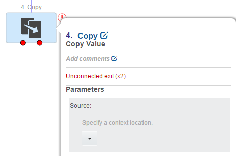
Click the parameter that you want to set and then click the down-arrow to open a list of context locations that reference the external concepts.
Figure 2-2 illustrates the groupings and the list of external concepts.
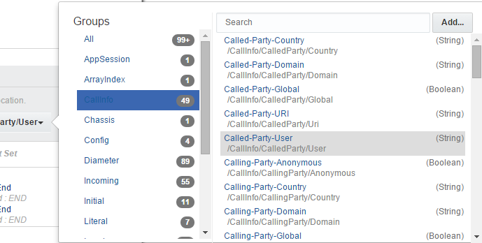
Select a particular group to filter external concepts to only those that belong to the group.
Enter a keyword in the Search field to narrow the list to those entries that contain the keyword in either the concept name or the context location.
Table 2-3 describes the groupings into which OCECAS organizes external concepts:
Table 2-3 External Concepts Groupings
| External Concept Group | Description |
|---|---|
|
AppSession |
All data related to the SIP Application Session, including the Session ID and the last accessed time. |
|
ArrayIndex |
These values are used to define dummy array index values used in charging control flows. |
|
CacheData |
Provides context access to a Coherence cache. Currently used to store registration data, which stays in the cache until the registration expires. PrimaryKey and SecondaryKey must be set to access data in the cache. |
|
Call Info |
Information derived from the call, for example, the calling party and the called party. |
|
Chassis |
Data required for chassis. |
|
Compiled Data |
Control flow data derived from compilation. |
|
Configuration Data |
Data related to the configuration. Includes, for example, the ATU-STI url, the conference factory URI, whether charging is enabled, and so on. |
|
Diameter Field Group |
Incoming and outgoing credit control messages. |
|
EDR Field Group |
Data from an Event Detail Record. |
|
Incoming Request |
Data that is presented in an incoming request, including Call-ID, Timestamp, Request-URI, and so on. |
|
Initial Request |
Data presented in the initial request in an SIP header, for example the From, Call ID, P-Asserted-Service, and so on. |
|
Local Context |
Data that has been defined in the control flow. |
|
Notified Field Group |
Data from the fields of a notification message. |
|
Outgoing Request |
Data presented in an outgoing request, for example Contact, Expires, SDP video streams, and so on. |
|
SDP Data |
Data from the Session Description Protocol. |
|
Service Data |
Data used by services or applications, including service-specific data and general data, for example, the home network ID list for VoLTE and VoWiFi service, the T-ADS preferences for SRVCC service, country-code mapping for all services, and so on. |
|
Service Loader |
External concepts that are used by bootstrap control flows such as SIP INVITE, SIP OPTIONS, and so on, to decide which sub-application or service to run. |
|
SIP Application Session Data |
Data from the SIP Application session. |
|
User Profile |
Data from the user's profile, such as HomeCountry, TimeZone, the control flow names of registered services, Language, MSISDN, STN-SR, and so on. |
OCECAS uses context locations to locate information associated with a session. For example, outgoing credit control messages that are created during a session are located with the information about Multiple Services Credit Control (MSCC) at /Diameter/Outgoing/MSCC.
You can also add a local context external concept to a control flow.
Adding an External Concept
You can add a local context external concept when you configure an Activity that accepts an external concept as a parameter value.
To add an external concept to a control flow:
-
Open the control flow.
See "Locating a Control Flow" for more information.
-
Double click the Activity whose parameter requires the external concept.
The configuration panel opens.
-
Click the parameter you want to set.
A dialog box displays the groups and a list of the external concepts.
-
Click Add.... See Figure 2-2 for an example.
The Add External Concept dialog box displays.
-
Enter the information to describe the external concept.
-
In the Name field, enter a unique name for the concept. Name must be alphanumeric characters plus -, _, and space.
-
In the Path field, specify the location of the runtime data, beginning with /Local/. For example:
/Local/new_concept_namePath must be alphanumeric characters plus -, _, and /.
-
For the Data Type field, select from String, Integer, Float, Boolean, Date, MapArray, StringArray, Integer Array, and FloatArray.
-
-
Click Confirm.
The external concept is added and displays as a selection in the Local group.
About Charging Concepts
Charging concepts consist of data that results from some calculation such as the number of used units since the last request, or data that the Activities need to know explicitly, such as the validity time of the granted quota. OCECAS generates this information when it is required for an outgoing message or a message receipt. You normally use the request or response message template to copy these values to or from the context map for the session.
Working with Charging Templates
You need to reference the appropriate values for the Request Template and Answer Template parameter when you define the following Activities:
-
Start Charging Session
-
Event Charge
-
Update Charging Session
-
End Charging Session
For the template parameters, OCECAS provides four Charging templates called ACAnswer, ACRequest, CCAnswer, and CCRequest. Select a corresponding template for the Activity.