| Oracle® Retail Predictive Application Server Cloud Edition User Guide Release 19.0 F24877-28 |
|

 Previous |
 Next |
| Oracle® Retail Predictive Application Server Cloud Edition User Guide Release 19.0 F24877-28 |
|
Previous |
Next |
You can view data in RPASCE in various ways. Changing the level, amount, and layout can make it easier for you to complete certain activities and tasks. For example, a manager might want to view data at a higher level of the product dimension, while a planner can work at a lower level of the dimension to complete necessary tasks. You make these view changes in Edit View.
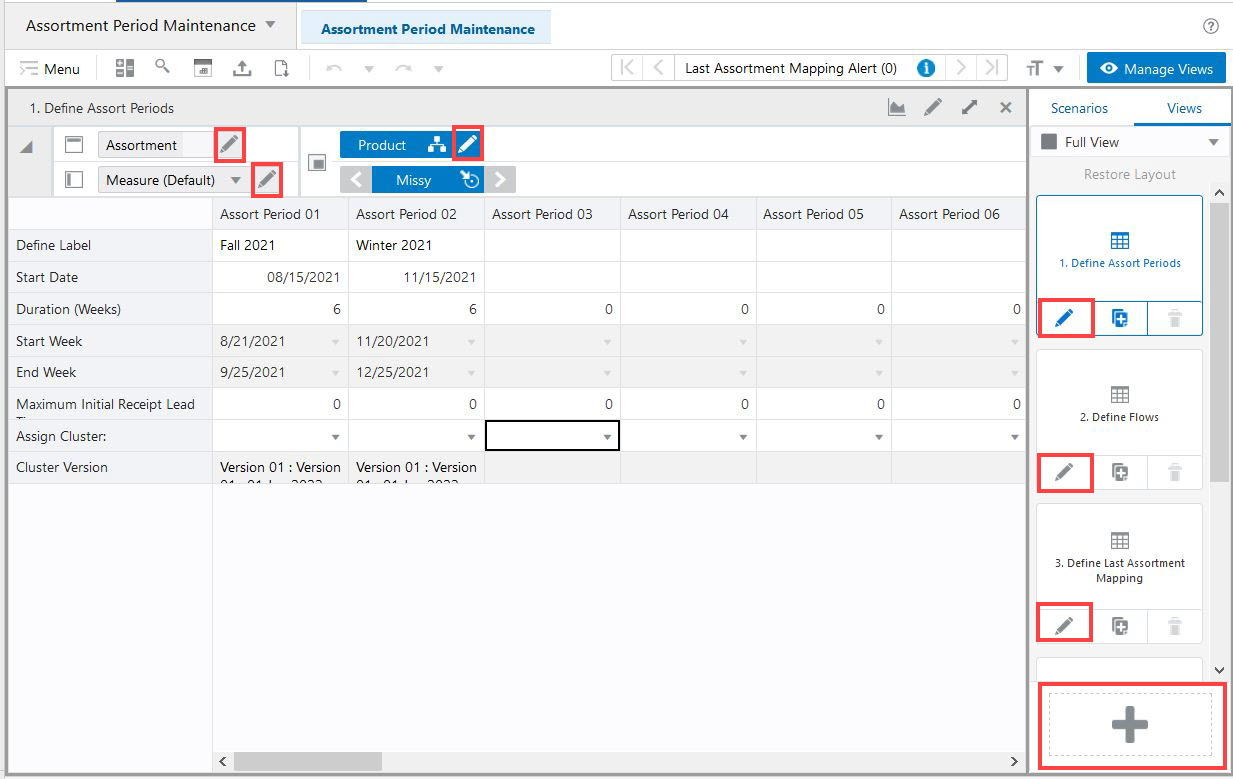
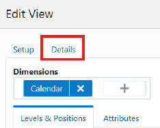
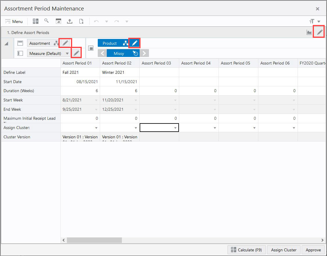
To open Edit View, click any of the following places. If you click any of the dimension tiles in the Details tab of the Edit View window, you launch Edit View. Any other way launches the Setup tab of the Edit View window. Refer to Figure 7-1 and Figure 7-2.
Edit on the View Title Bar
Edit on the dimension tiles in an open view
Edit on a view tile in the View Management Drawer
Edit on the Detached view
New View in the View Management Drawer
Figure 7-2 Launching Edit View from the Detach View
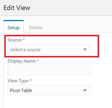
Choose a source for the View. Any View in the View Management Drawer can be selected. This determines the measures available in the new view you are creating.
Figure 7-3 Select Source in Edit View While Adding a New View
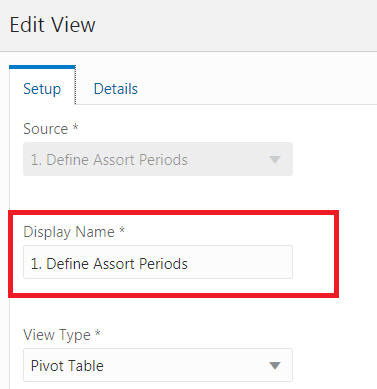
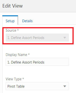
Any other way of launching edit view except Add View displays the source as an uneditable field. You will not be able to change the source of a view.
Figure 7-4 Display Source in Edit View While Editing an Existing View
You can change the view display name using the Edit View as shown in Figure 7-5. You must be in the Setup tab of Edit View to complete this action.
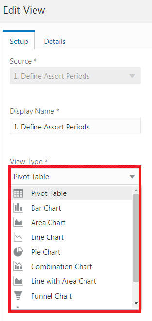
You can change the view type using the Edit View as shown Figure 7-6. You must be in the Setup tab of Edit View to complete this action.
The following view types can be changed.
Pivot Table
Bar Chart
Area Chart
Line Chart
Pie Chart
Combination Chart
Line with Area Chart
Funnel Chart
Pyramid Chart
Polar Chart
To move and re-order dimension tiles, complete the following steps:
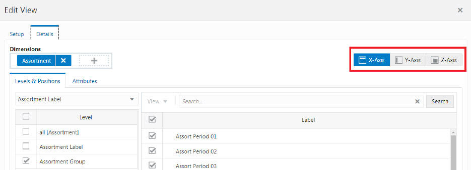
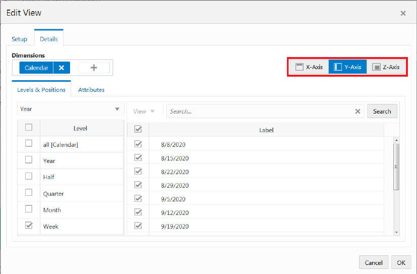
Once Edit View is open, click the Details tab to see the different dimensions, axes, levels, positions, and measures.
To view the contents of each axis, click the different Axis Toggle buttons in the top right.
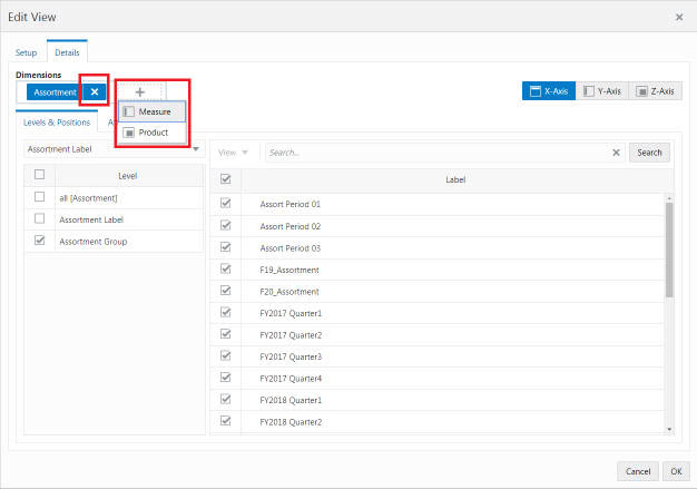
Once you have the correct axis displayed, use the X button or the Plus button in the Dimension Tiles area to remove or add a dimension to that axis.
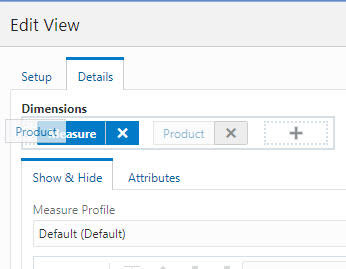
You can also re-order the dimensions by dragging and dropping the dimension tiles next to another tile or swapping tiles with one another.
Use Edit View to change the data shown at each level in a view.
You can view alternate branches of the hierarchy or dimension by using the Branch Selector list. When you select a different branch in the list, you notice that different dimensions are in the Levels and Dimensions area.
Once Edit View is open, click the Details tab to see the different dimensions, axes, levels, positions, and measures.
To view the contents of each axis, click the different Axis Toggle buttons in the top right.
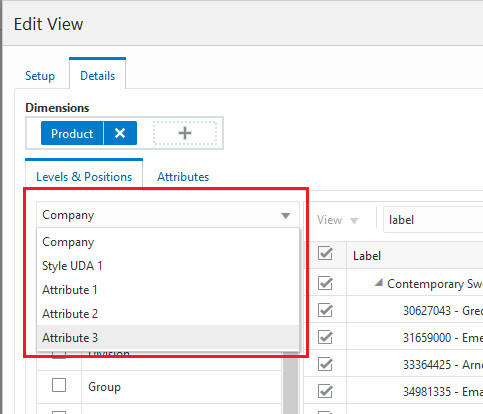
Click the Branch Selector list in the Levels and Positions area for the Product dimension to see the different branch options for the Product dimension (Company vs Department Group).
Figure 7-13 Branch Options (Company vs Department Group)
When you select a different branch, you see different dimension levels that you can choose from in the Levels and Positions area.
Figure 7-14 Branch Dimension Levels and Positions
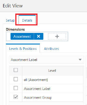
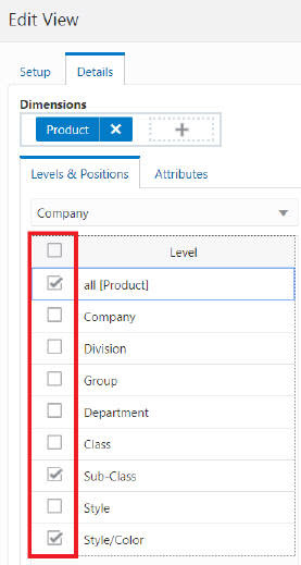
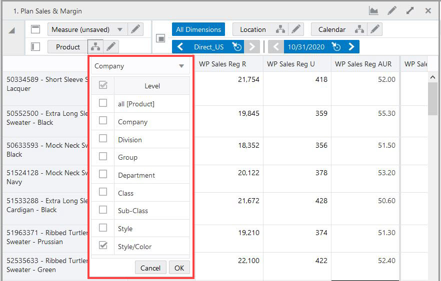
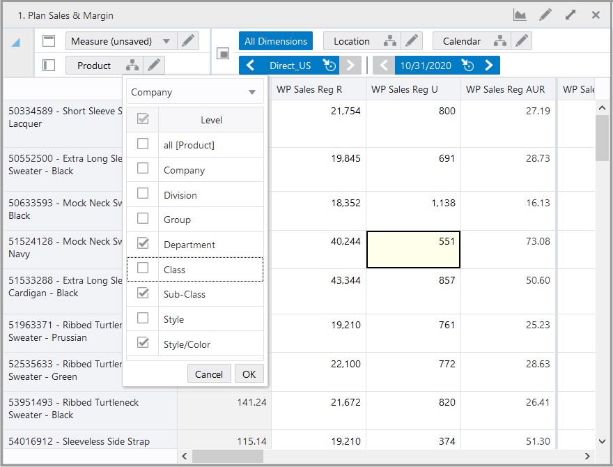
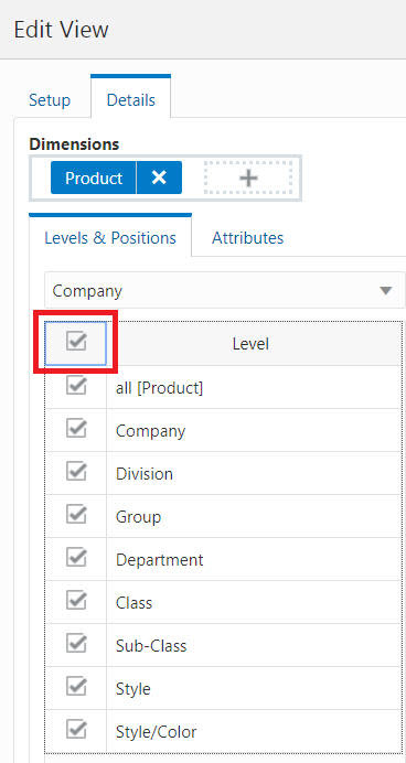
To show or hide levels, complete the following steps:
Open the Details tab in Edit View.
Select or clear the boxes to the left of the levels to change the visible levels.
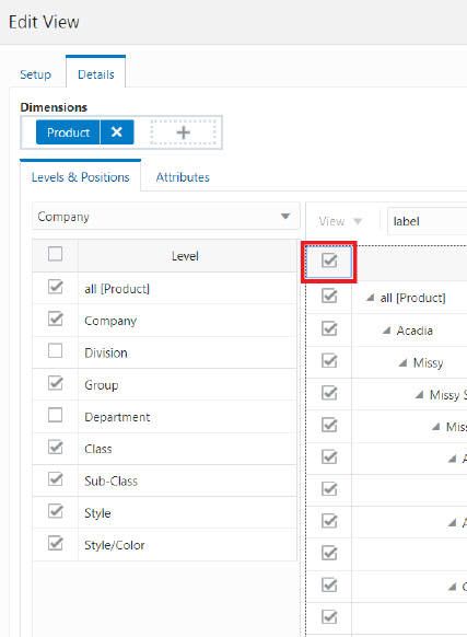
To select all or clear all, select the box at the top of the levels.
Figure 7-16 Selecting and Deselecting All Levels
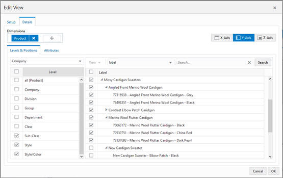
Once the level has been selected in the left panel, click the Expand button next to the different positions in the right panel to expand or contract the levels.
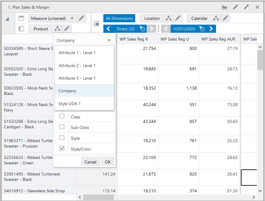
Alternatively, you can select branch hierarchy and levels without navigating to edit view. A hierarchy icon is available to access the list to change the branched hierarchy and level.
Figure 7-18 Branch Hierarchy and Level Selector Icon
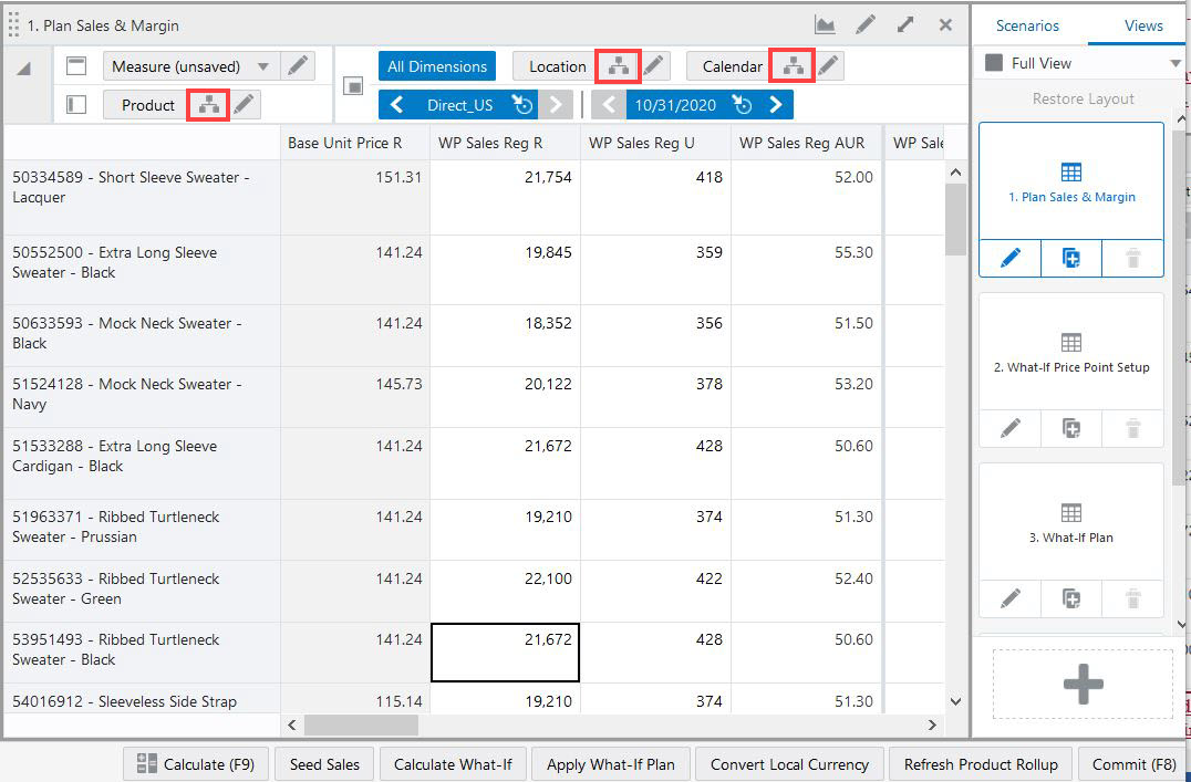
To change the branch alternate hierarchy and level without navigating to the edit view, perform the following the steps:
Click Hierarchy available at the dimension tile.
From the branch hierarchy list, select the alternate hierarchy.
Based on the selected Branch Hierarchy, you can see the dimension levels list to select from.
Select the levels by either select the check box or level label.
This section provides details about individual data display.
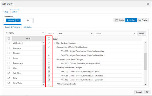
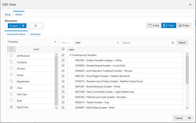
Once Edit View is open to the Details tab, you can show and hide positions in the view. The non-calendar positions are sorted alphabetically by default, based on the Label attribute. The Calendar positions are sorted chronologically.
Select or clear the boxes to the left of the positions to change the visible positions.
To select all or clear all, click the box at the top of the positions.
You can also select and deselect positions using the context menu (right-click) option. This option is an alternative to select or deselect positions in Edit view. You can use context menu option to select or deselect multiple positions simultaneously.
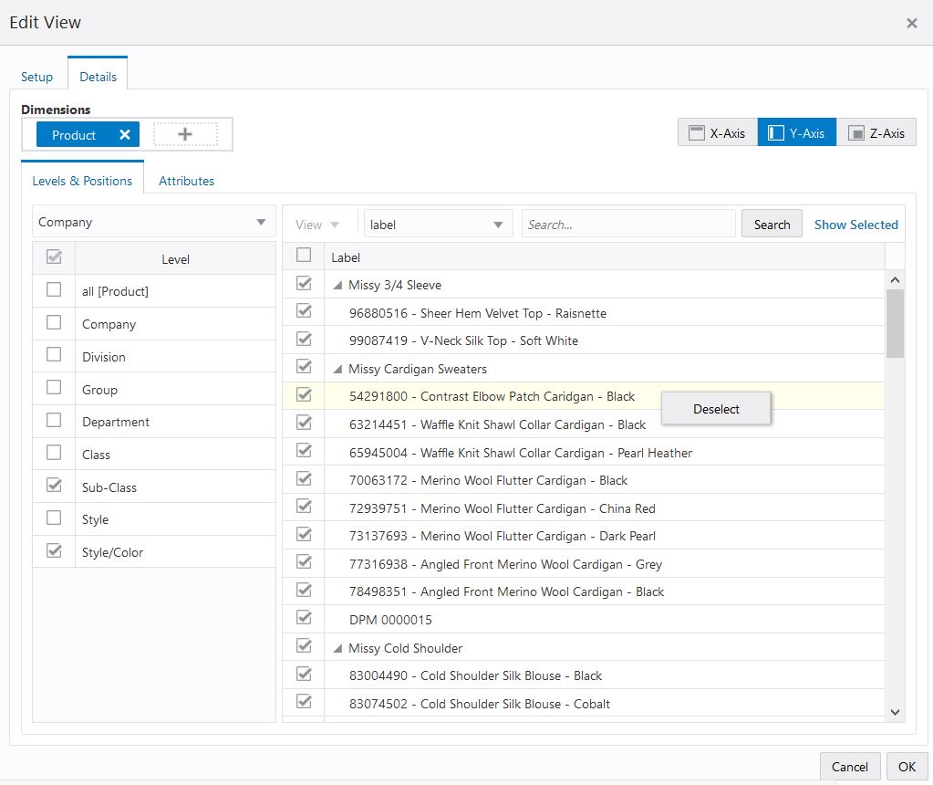
To select a position, right-click on the position and choose Select. Similarly, to deselect a position, right-click on a selected position and choose Deselect.
When you want to select or deselect multiple positions, select multiple positions by Using a mouse drag with a Shift or Ctrl key and right-click to opt for Select or Deselect positions.
Figure 7-24 Context Menu Select Position in Edit View
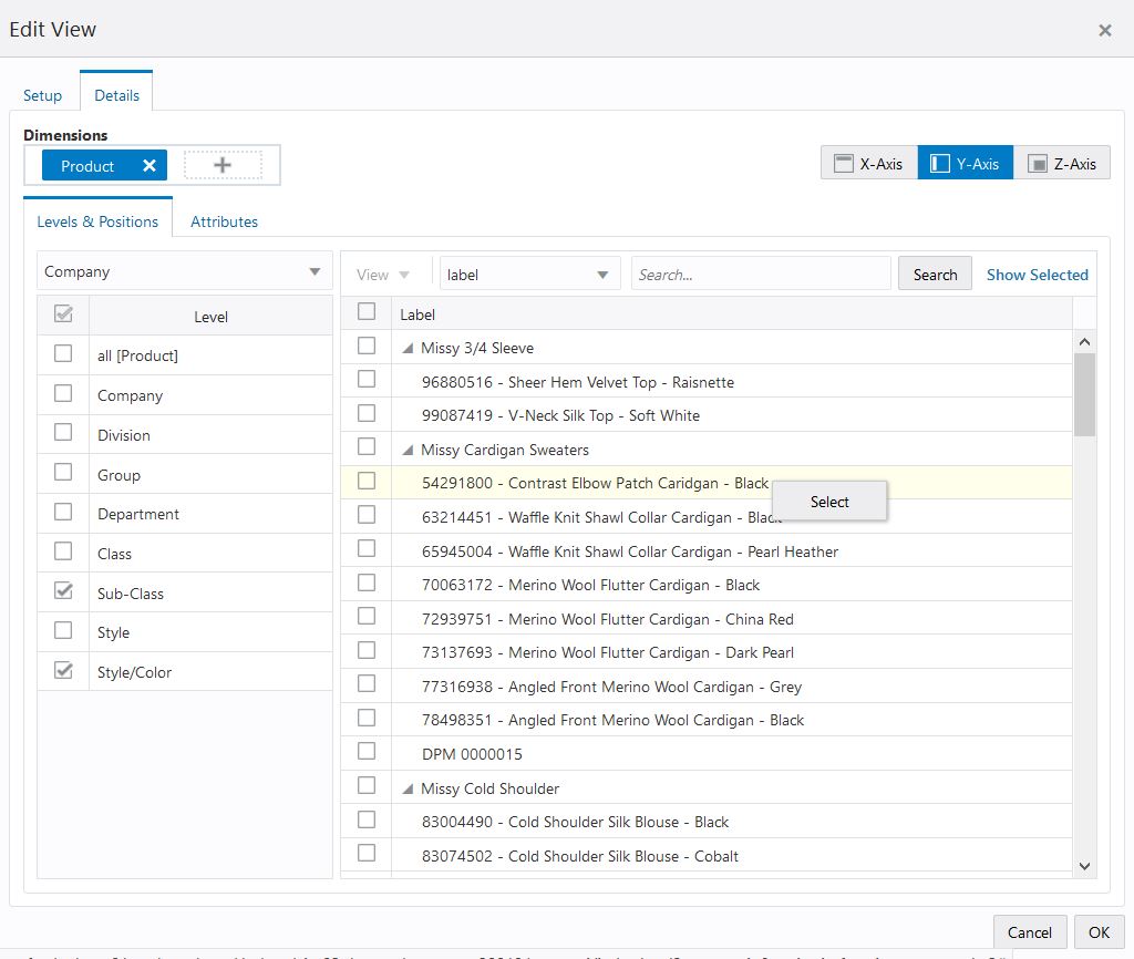
Figure 7-25 Context Menu Deselect Position in Edit View
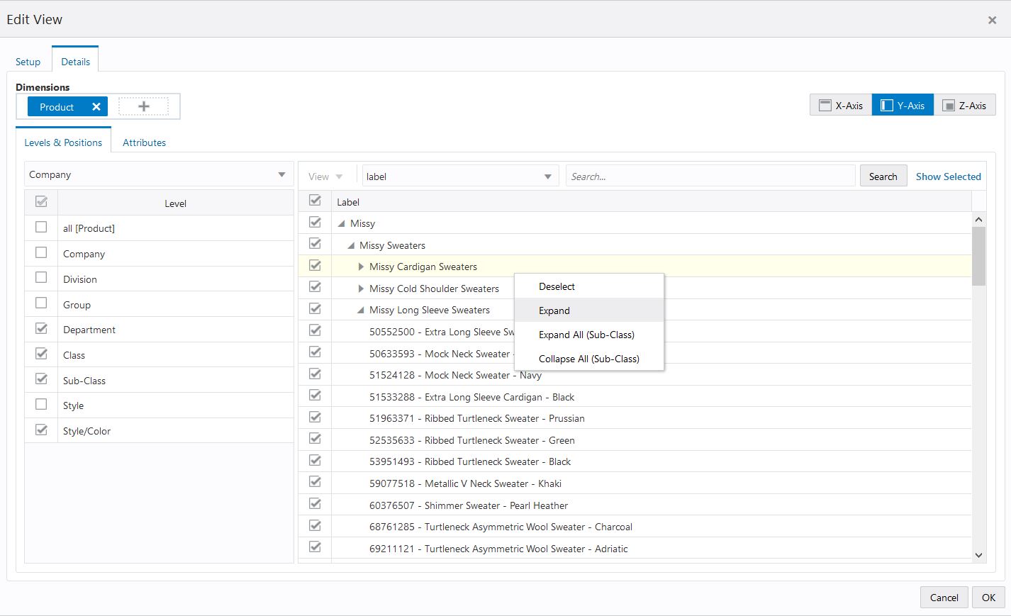
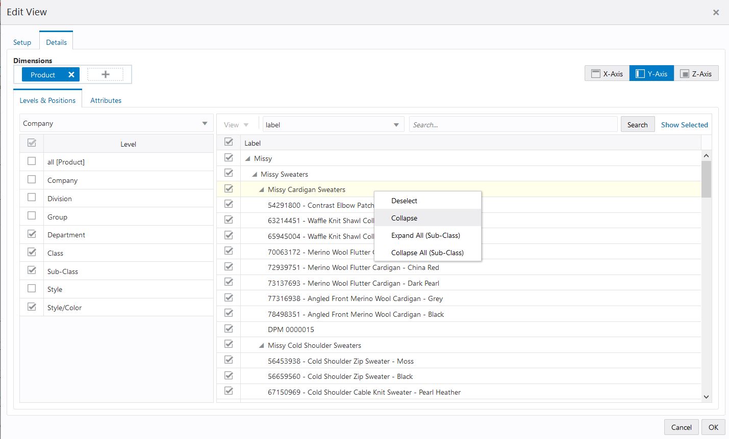
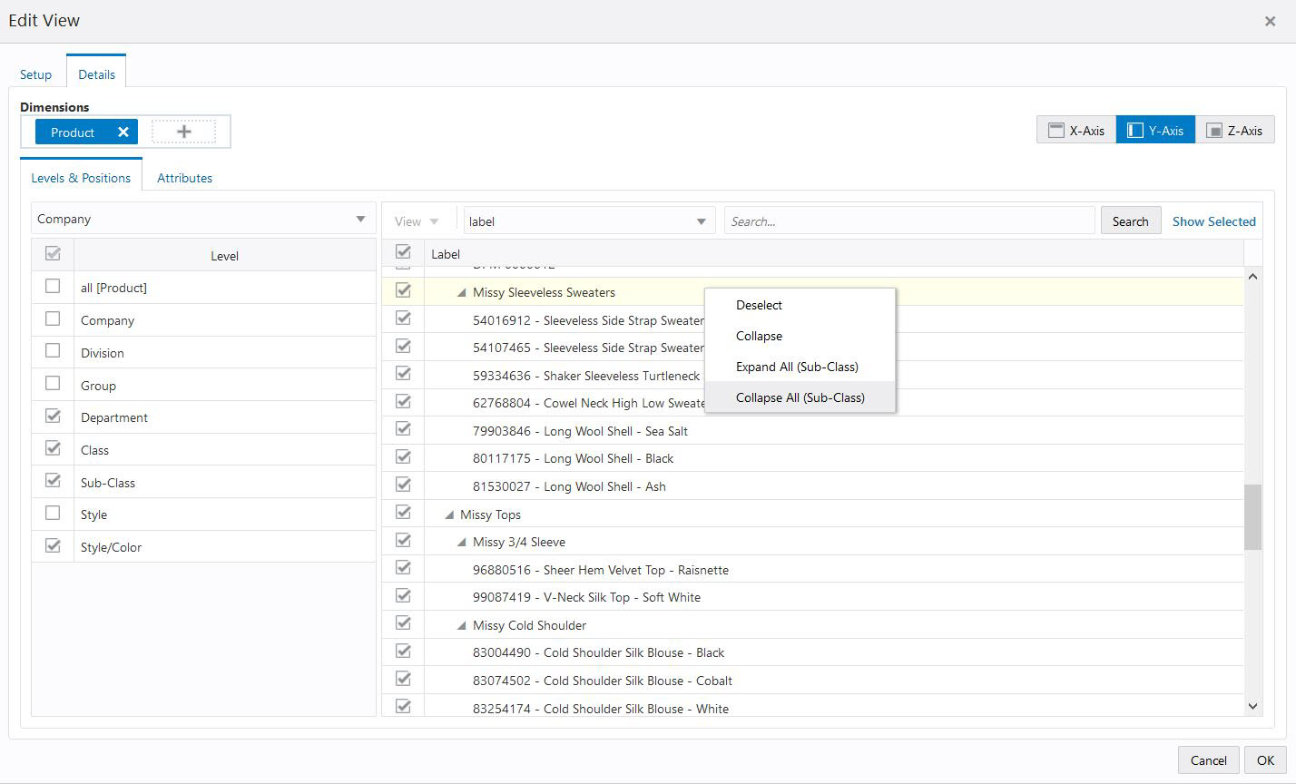
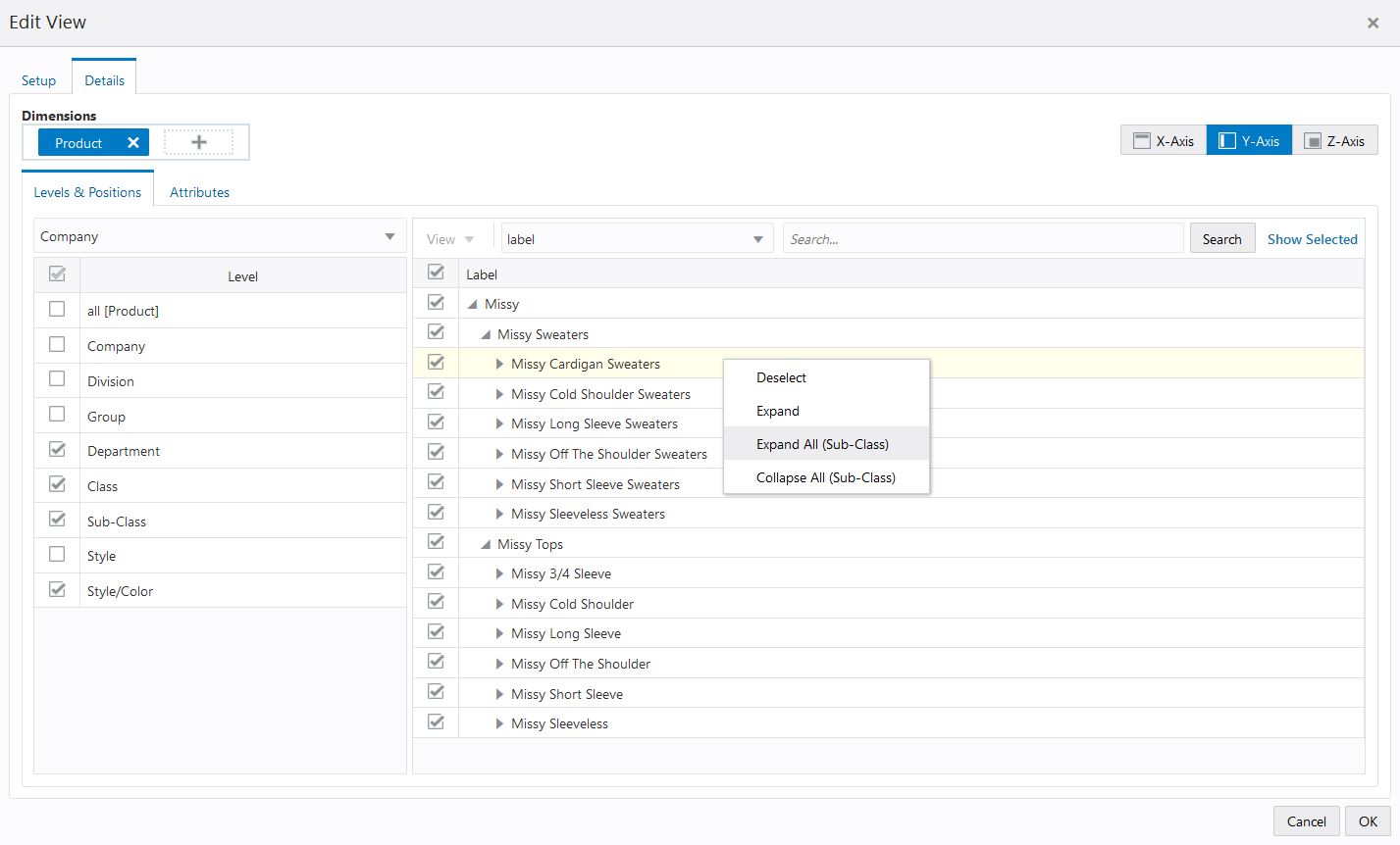
Collapse functionality allows a planner to group the child level positions to parent level. Expand functionality allows a planner to drill-down parent level to view all the child level positions. Collapse and expand function helps you to see all the positions in edit view that is meaningful to you.
To collapse or expand the dimension position you can use context menu (right-click) option. You can right-click on a parent level position, you can select expand function to see all the child positions. Similarly, to group the child level position, you can right-click on the parent position and select Collapse.
The same functionality of collapse has been extended to Collapse All which collapses all the child level positions for the selected dimension level in Edit view. And Expand all function expands all the child level position for the selected dimension level in Edit view. The selected dimension level is specified next to Collapse All or Expand All in the context menu. With this function, you can quickly collapse or expand view the list of positions as desired.
|
Note: Expand or Collapse levels altered in the Edit View Overlay do not change the Expand or Collapse levels in the pivot table. |
You can filter the positions by attributes when you review your plan. This allows you to examine the different options that you care about and make decisions. The attribute filter is visible only when attributes are associated with at least one of the selected levels. The filter picklist is by default set to the label attribute.
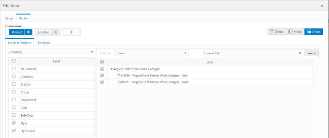
Select the required attribute as a filter and search for the positions that have the attribute value you selected. For example, if you select Color as the filter and then select Black from the list, all the positions that have Black as the color attribute value will be listed.
Figure 7-30 Filter Positions (Edit View)
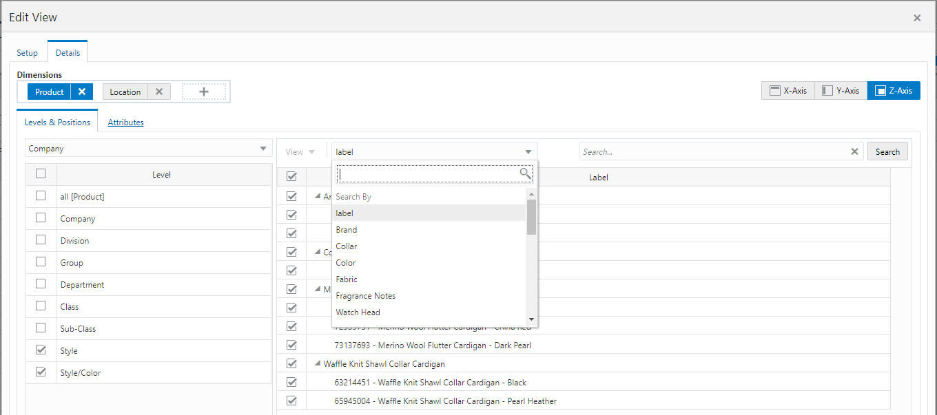
Figure 7-31 Filter Positions by Attribute Example
Once Edit View is open to the Details tab, click on Attributes tab. you can view and sort attributes in the view.
Select or clear the boxes to the left of the attribute name positions to viewing and sort availability of particular attributes.
Figure 7-32 Select Attributes for Viewing and Sorting Positions
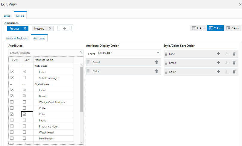
You can change the attribute display order by dragging and dropping the attributes or delete them from display order by clicking on the delete icon. You can also use the level selection to view the attributes at particular hierarchy level.
You can change the selected level sort order by changing the ascending and descending order arrows or delete them from sort order by clicking on the delete icon.
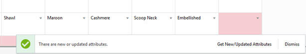
Whenever new or updated item attribute types or attribute values are available in planning, when opening an existing workspace, the planner will receive a snack-bar notification indicating that new or updated attributes are available. As a planner or buyer, you want to be able to filter and sort using new item attributes as soon as they are available in planning. You can use Refresh Attributes in the Action Menu to view the new or updated attributes. You can select the required attributes from the Get New/Updated Attributes list in order to use them in your planning throughout the current workspace.The Get New/Updated option is available in the Action menu on the Quick Access toolbar and in the Attributes tab of Edit View.
Figure 7-33 New or Updated Attribute Notification
Measure profiles are customized groups of measures that you can create and use in views. Instead of adding or removing measures from the default measure list each time you work with a particular view, you can save that customized group of measures as a measure profile and load it into the view. By creating a measure profile for each set of measures that you frequently use, you reduce the amount of time it takes to set up a view.
Measure profiles are created at the view level and are available in all views and copies of that view. Measure profiles are saved as part of the formatting. Depending on how you save the formatting, you can make your measure profiles available to other users. For more information, see Chapter 10, "Formatting."
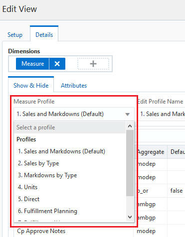
Application-defined measure profiles are configured with the base application and cannot be edited or deleted. If you make a change to the selected measures, the profile cannot be saved as the original profile name, but can be saved with a new name. These profiles are listed in the Profiles list in the Profiles section.
Figure 7-34 Application-Defined Measure Profile
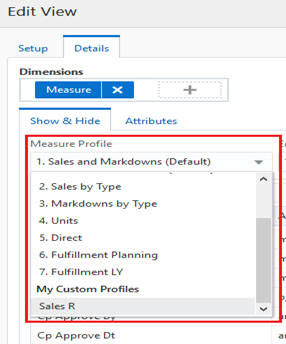
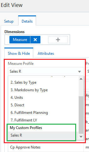
If you generally only work with certain measures, you can create a user-defined measure profile by saving a measure profile. These profiles are usually created by starting with an application-defined or user-defined measure profile, updating the selected measures as needed, and saving the measure profile with a different name. They are listed in the Profiles list in the My Custom Profiles section, and they can be deleted.
Figure 7-35 User-Defined Measure Profile
To create a measure profile, complete the following steps:
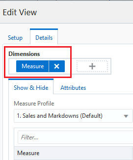
Open Edit View and then go to the Measures Dimension Tile.
To create a new measure profile, first open any of the existing measure profiles from the Measure Profile list.
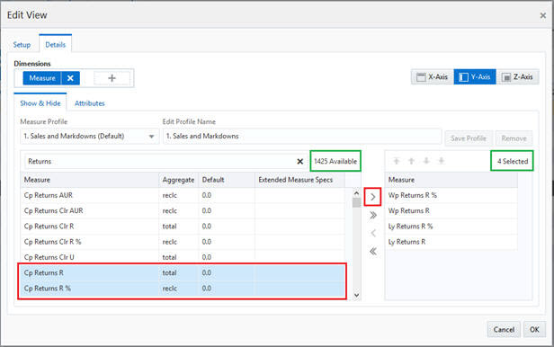
Add and remove desired measures. Select one, multiple, or all Available Measures and then add them to the Selected Measures list. Similarly, select one, multiple, or all Selected Measures and remove them by moving them to the Available Measures list.
Use the single arrow buttons to add or remove one or more measures.
Use the double arrow buttons to add or remove all the measures.
When measures are added to the Selected Measures list, they are added after the last highlighted row in the list. This allows you to insert measures anywhere you choose in the list. If no row is highlighted, measures are added to the end of the list.
Measures that have been removed are always added back to the Available Measures list in alphabetical order.
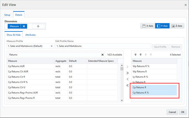
The total count of the available measures and selected measures is displayed. See Figure 7-38. The count of the selected measures is updated when you add or remove measures to or from the Selected Measures list.
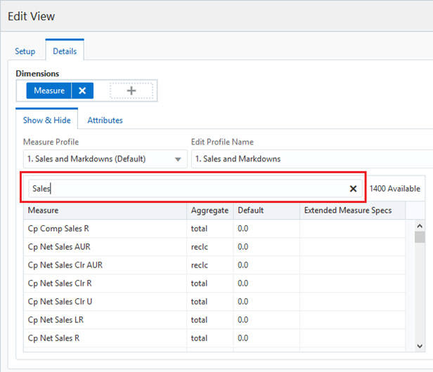
You can filter or search the Available Measures list. For example, if you type Sales in the Filter… text box, then the available list of measures will be filtered to display measures containing the word Sales. Click X to clear the text in the Filter text box.
Note that the available count represents the total available measures, not the filtered available measure count. When the Available Measures list is filtered, clicking on the double arrow button will add only the filtered list of measures to the Selected Measures list.
Figure 7-40 Selected Measures Added to Selected Measures List
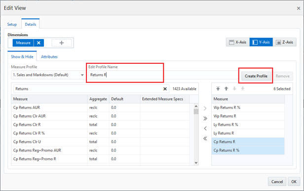
If you make changes to the selected list of application-defined measure profiles, the measure profile name will temporarily display None Selected/Unsaved until you create a new profile. In addition, the measure tile will indicate the current measure profile as unsaved.
Type a profile name in the Edit Profile Name text box and click Create Profile.
To edit a measure profile, complete the following steps:
Open Edit View and go to the Measures Dimension tile.
Select a Custom Measure Profile from the Measure Profile list.
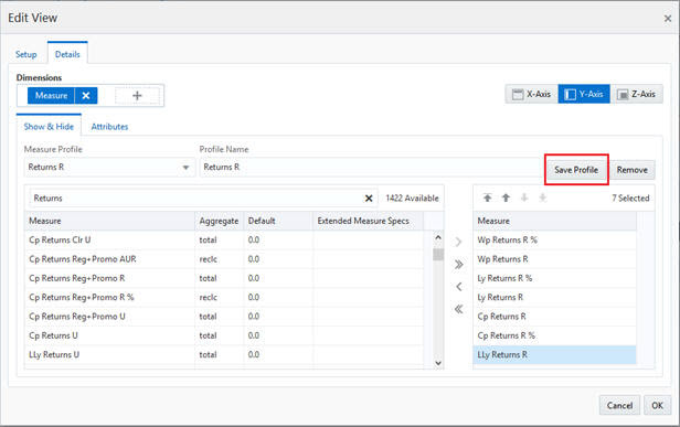
Add or remove measures to or from the Selected Measure list.
Click Save Profile. The measure profile is updated to reflect the selected measures.
If you edit a System Measure Profile, you must create a new measure profile; if you do not, the changes made in the Selected list will be lost when you switch between measure profiles.
To delete a measure profile, complete the following steps:
Open Edit View and go to the Measures Dimension tile.
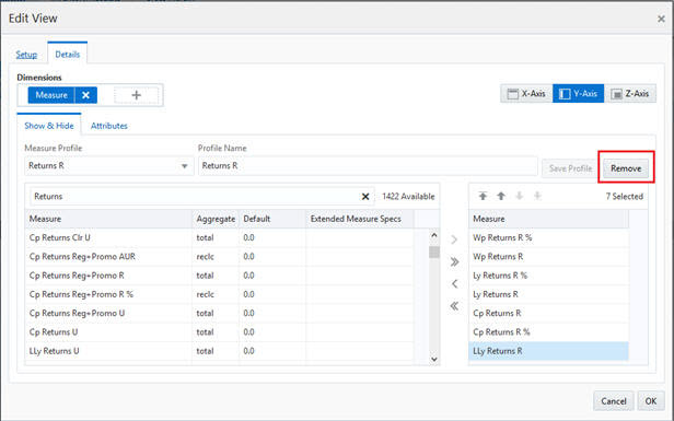
Select a custom measure profile from the Measure Profile list.
Click Remove. The measure profile is deleted. You cannot delete a system measure profile.
You can reorder the measures using the Measure Edit View window.
You can select a measure in Selected Measures and move the measures in following ways:
Figure 7-44 Re-Order Measures Using Arrows
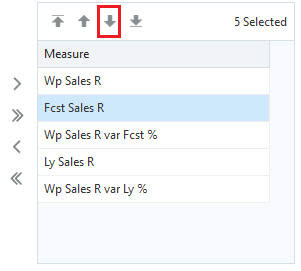
Move First–Moves selected measures up to the top of the list.
Move Up–Moves selected measures up one position relative to the selected measures
Move Down–Moves selected measures down one position relative to the selected measures
Move Last–Moves selected measures down to the bottom of the list.
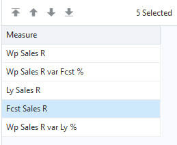
In the following example, Fcst Sales R has been selected. Clicking on Move Down causes the measure to be moved below Wp Sales R var Fcst %.
You can also select measures and use the context menu to reposition the selected measure row. In the following example, Fcst Sales R has been selected. Right- click the selected measure and select the Cut option from the context menu. Then, select the measure above or below the one where you want to paste the Fcst Sales R measure. Select Paste Before or Paste After as necessary in order to re-position the Fcst Sales R measure. As shown in Figure 7-45 and Figure 7-46, selecting Paste After on Ly Sales R measure, pasted Fcst Sales R measure after Ly Sales R measure.
When the Cut operation is followed by the contiguous selection of more than one rows and the Paste Before/After operation, Paste Before pastes the clipboard data before the first selected row and Paste After pastes the clipboard data after the last selected row.
When the Cut operation is followed by the non-contiguous selection of more than one rows and the Paste Before/After operation, Paste Before pastes the clipboard data before the last selected row and Paste After pastes the clipboard data after the last selected row.
Figure 7-45 Re-Order Measures: Cut Selected Measure
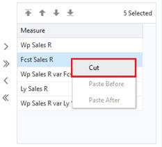
Figure 7-46 Re-Order Measure: Paste Selected Measure
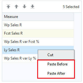
Figure 7-47 Re-Order Measure: Results of Paste