This alarm indicates that a power fault has been
identified by the breaker panel. The LEDs on the center of the breaker panel
(see
Figure 3-4)
identify whether the fault occurred on the input power or the output power, as
follows:
A power fault on input power (power from site
source to the breaker panel) is indicated by one of the LEDs in the PWR BUS A
or PWR BUS B group illuminated Red. In general, a fault in the input power
means that power has been lost to the input power circuit.
Note:
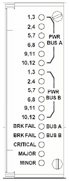
LEDs in the PWR BUS A or PWR BUS B group
that correspond to unused feeds are not illuminated; LEDs in these groups that
are not illuminated do not indicate problems.
A power fault on output power (power from the
breaker panel to other frame equipment) is indicated by either BRK FAIL BUS A
or BRK FAIL BUS B illuminated RED. This type of fault can be caused by a surge
or some sort of power degradation or spike that causes one of the circuit
breakers to trip.
Figure 3-4 Breaker Panel LEDs
Severity:
Major
Instance:
May include AlarmLocation, AlarmId, AlarmState,
AlarmSeverity, and bindVarNamesValueStr
HA Score:
Normal
Auto Clear Seconds:
0 (zero)
OID:
TPDBrkPnlBreakerError
Alarm ID:
TKSPLATMA26
Recovery:
Verify that the same alarm is displayed by both
servers. The single breaker panel normally sends alarm information to both
servers:
If this alarm is displayed by only one server,
the problem is most likely to be with the cable or the server itself. Look for
other alarms that indicate a problem with the server and perform the recovery
procedures for those alarms first.
If this alarm is displayed by both servers, go to
the next step.
For each breaker assignment, verify that the
corresponding LED in the PWR BUS A group and the PWR BUS B group is illuminated
Green.
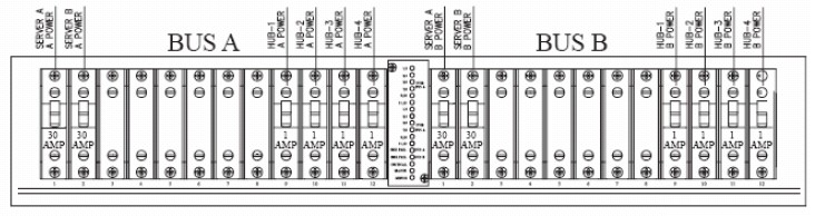
Figure 3-5 Breaker Panel Setting
If one of the LEDs in the PWR BUS A group or the PWR
BUS B group is illuminated Red, a problem has been detected with the
corresponding input power feed. Perform the following steps to correct this
problem:
Verify that the customer provided source for
the affected power feed is operational. If the power source is properly
functioning, have an electrician remove the plastic cover from the rear of the
breaker panel and verify the power source is indeed connected to the input
power feed connector on the rear of the breaker panel. Correct any issues
found.
Check the LEDs in the PWR BUS A group and the
PWR BUS B group again.
If the LEDs are now illuminated Green, the
issue has been resolved. Proceed to step 4 to verify that the alarm has been
cleared.
If the LEDs are still illuminated Red, continue
to the next sub-step.
Have the electrician verify the integrity of
the input power feed. The input voltage should measure nominally -48VDC (that
is, between -41VDC and -60VDC). If the supplied voltage is not within the
acceptable range, the input power source must be repaired or replaced.
Note:
Be sure the voltmeter is connected properly.
The locations of the BAT and RTN connections are in mirror image on either side
of the breaker panel.
If the measured voltage is within the
acceptable range, the breaker panel may be malfunctioning. The breaker panel
must be replaced.
Check the LEDs in the PWR BUS A group and the
PWR BUS B group again after the necessary actions have been taken to correct
any issues found
If the LEDs are now illuminated Green, the
issue has been resolved and proceed to step 4 to verify that the alarm has been
cleared.
If the LEDs are still illuminated Red, skip to
step 5
Check the BRK FAIL LEDs for BUS A and for BUS B.
If one of the BRK FAIL LEDs is illuminated Red,
then one or more of the respective Input Breakers has tripped. (A tripped
breaker is indicated by the toggle located in the center position.) Perform the
following steps to repair this issue:
For all tripped breakers, move the breaker down
to the open (OFF) position and then back up to the closed (ON) position.
If all of the BRK FAIL LEDs and all the LEDs in the
PWR BUS A group and the PWR BUS B group are illuminated Green, there is most
likely a problem with the serial connection between the server and the breaker
panel. This connection is used by the system health check to monitor the
breaker panel for failures. Verify that both ends of the labeled serial cables
are properly secured. If any issues are discovered with these cable
connections, make the necessary corrections and continue to the next step to
verify that the alarm has been cleared, otherwise it is recommended to run
syscheck and contact
unresolvable-reference.htm#GUID-DD0927BD-FD0B-4CEB-86E9-98A33C12D4E0
Run syscheck.
If the alarm has been cleared, the problem is
resolved.