Kitchen Display System Installation
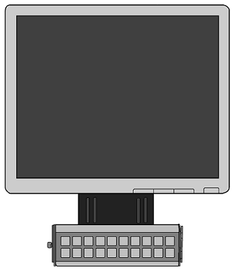
The Kitchen Display System is composed of three components: an Ethernet-based controller (the Restaurant Display Controller [RDC] or the Kitchen Display Controller [KDC] 210), LCD monitor, and wired or wireless MICROS bumpbars.
Figure 22-2 Typical KDS Monitor Bumpbar and Mounting Bracket

- KDS Mounting
- KDS Controllers
- MICROS Wired Bumpbar Installation Considerations
- MICROS Wireless Bumpbar Installation Considerations
Parent topic: Kitchen Display System (KDS)
KDS Mounting
A wide variety of LCD and bumpbar mounting options are available. Contact your Oracle MICROS representative if the LCD mounting options need to be determined.
Parent topic: Kitchen Display System Installation
KDS Controllers
KDS Controllers (the Restaurant Display Controller and the Kitchen Display Controller 210) require a Cat 6 faceplate and patch cable near each location. Refer to the Oracle MICROS Kitchen Display Controller 210 Quick Reference Guide for detailed information about the KDC 210.
Parent topic: Kitchen Display System Installation
MICROS Wired Bumpbar Installation Considerations
The MICROS Bumpbar MBB-10 and MBB-20 User Guide contains information for installing the wired bumpbar.
The MICROS Wired Bumpbar is supplied with a 6ft. (1.8M) cable. The 11 foot cable is also available (PN 700503-070-PT).
Parent topic: Kitchen Display System Installation
MICROS Wireless Bumpbar Installation Considerations
The MICROS Wireless Bumpbar MBB-10 and MBB-20 User Guide contains information for installing the wireless bumpbar.
Before installing the mounting brackets, consider the following site related issues to ensure the best possible functionality from the MWBB in an active RF environment.
-
Range
Distances up to 30 feet are possible when the dongle and bumpbar are within sight of each other, with no obstructions in the path of the RF signals.
As the number and type of obstructions between the dongle and bumpbar increase, the range decreases.
-
Classification of RF Obstructions
RF signals encounter two types of obstructions that either weaken or reflect the signal, depending on its material composition.
The first type of obstruction is one that allows the signal to pass through, but attenuates, or weakens it. Some examples include walls constructed of wood, drywall, people, and concrete block. The amount of attenuation is proportional to the total thickness of materials that the RF signal must penetrate when traveling the line-of-sight path.
The second type of obstruction is one that reflects the RF signals, allowing little or none to pass through. The reflected RF energy can cause interference even when the dongle and bumpbar are located within line-of-sight. Any type of metallic substance falls into this category. This includes objects such as stainless steel food preparation areas, walk-in freezers, steel doors, and steel support beams.
-
Local RF Interference
The RF signals emitted by the MWBB are located in the unlicensed 2.40 - 2.50 GHz ISM band. Nearby occupants of this band include microwave ovens (2.485 GHz), 802.11 b/g Wi-Fi, cordless phones, IEEE 802.15.4 (WPAN), ZigBee, and other personal area networks. Ensure the MWBB is located as far from these devices as possible.
The greater the distance between the dongle and the bumpbar, plus the greater the number of obstructions between the two devices, allows extraneous RF devices to impact the operation of the wireless bumpbar.
In cases where the site is too noisy in terms of RF interference, Oracle MICROS recommends the use of the MBB-10 and MBB-20 wired Bumpbars.
Parent topic: Kitchen Display System Installation