Terminology
This section describes how to migrate a signaling network that uses the Duplicate Point Code feature to support a National Spare network to a signaling network that uses the ITU National and International Spare Point Code Support feature to support a National Spare network
The term “enabled” refers to entering the enable-ctrl-feat command to provision the ITU National and International Spare Point Code Support feature.
The term “turn on” refers to entering the chg-ctrl-feat command to change the ITU National and International Spare Point Code Support feature status to on. After this feature is turned on, all MSU processing is performed using the ITU National and International Spare Point Code Support feature rules.
APC refers to the adjacent point code of a linkset. The APC is the point code of the adjacent node to which messages are routed. The APC can be one of these types of point codes:
- ANSI point code
- ITU-International point code
- ITU-International spare point code
- 14-bit ITU-National point code
- 14-bit ITU-National spare point code
- 24-bit ITU-National point code.
For more information on these point code types, see the Point Code Formats section.
SAPC refers to the secondary adjacent point code that is assigned to a linkset. For more information on secondary adjacent point codes, see the Configuring an ITU Linkset with a Secondary Adjacent Point Code (SAPC) procedure.
National traffic refers to traffic whose messages contain the national network indicator value 2 ( NI=10binary ).
National Spare traffic refers to traffic whose messages contain the national spare network indicator value 3 ( NI=11binary).
Assumptions
The examples used to illustrate the migration process use these assumptions.
- The group code aa is assigned to the point codes that are assigned to the nodes handling messages that contain the national network indicator value 2 (NI=10binary).
- The group code ab is assigned to the point codes that are assigned to the nodes handling messages that contain the national spare network indicator value 3 (NI=11binary).
- Only two nodes support the duplicate point code feature: STP 1 and STP 2.
- Between pairs of nodes, separate linksets exist for group aa and group ab. In this case, separate linksets exist between STP 1 and STP 2.
- The nodes are migrated to the ITU National and International Spare Point Code Support feature, one at a time, in three stages.
- Stage one involves upgrading all the nodes to the new software load, enabling the ITU National and International Spare Point Code Support feature for provisioning, and provisioning each node with the required point codes and routes.
- Stage two involves turning on the ITU National and International Spare Point Code Support feature on an adjacent pair of EAGLEs, one pair of nodes at a time, and changing the routing between these EAGLEs to use a single linkset.
- Stage three removes the components that are no longer needed after the migration has been completed.
- After the migration process is complete, a single linkset will remain between pairs of nodes. Each linkset will carry both National and National Spare traffic.
- A third linkset containing high-speed signaling links will be created to support both the National and National Spare traffic. The other two linksets will be removed later.
- Prior to merging both National and National Spare traffic for an adjacent pair of nodes onto a single linkset, the customer and Oracle will need to determine whether more links must be added to the linkset to support the higher traffic volume. If the linkset has already reached its limit of 16 links, and more links are required, the customer and Oracle will decide whether the customer must deploy high-speed signaling links.
- The
nis parameter value for all linksets whose point code suffix is ab is set to on.
- After an EAGLE has been upgraded to the ITU National and International Spare Point Code Support feature, the point codes that will bew assigned to these nodes will have to be provisioned with the same group codes that are currently assigned to these nodes.
- The routes for the National Spare traffic must be provisioned before the ITU National and International Spare Point Code Support feature is turned on for a node.
- The customer should not lose any traffic during the migration.
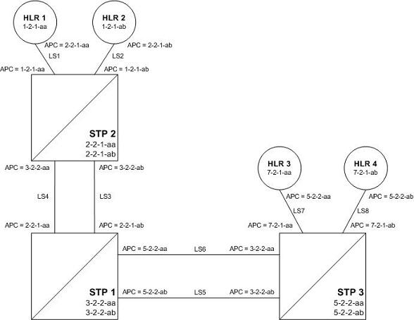
Figure 2-10 shows an example network that is not using the ITU National and International Spare Point Code Support feature.
Note:
For the figures shown in this section, a point code that is prefaced with “s” indicates a spare point code, and a point code that is not prefaced with an “s” indicates a non-spare point code. If a linkset includes an APC (adjacent point code) or SAPC that is prefaced with “s,” the linkset supports traffic to and from ITU-National spare point codes. If the linkset includes an APC or SAPC that is not prefaced with “s,” the linkset supports traffic to and from ITU-National point codes. A linkset that includes both ITU-National and ITU-National spare APC and SAPCs supports both national and national spare traffic. Point codes that are labeled within the STP nodes represent true and secondary EAGLE point codes.
Stage One
Figure 2-11 shows an example network. The items shown in bold are items that are added during this stage of the migration procedure.
The following steps are performed for each node shown in Figure 2-11, one at a time, as part of this stage of the migration procedure.
- Upgrade each EAGLE shown in Figure 2-11 to the software release that contains the ITU National and International Spare Point Code Support feature by performing the appropriate upgrade procedure.
- Enable the ITU National and International Spare Point Code Support feature on each EAGLE shown in Figure 2-11, by performing the Activating the ITU National and International Spare Point Code Support Feature procedure. Do not turn the feature on at this time.
Note:
Provisioning for the ITU National and International Spare Point Code Support feature can be performed once the feature is enabled. Message processing based on this feature is not performed until the feature is turned on.
- Add a new true ITU-National spare point code in the self identification table of each EAGLE by performing the Adding a Point Code to the Self-Identification of the EAGLE procedure at each EAGLE. For example, add these point codes:
- Point code s-3-2-2-ab to STP 1
- Point code s-2-2-1-ab to STP 2
- Point code s-5-2-2-ab to STP 3.
- Add one secondary ITU-National spare point code to each EAGLE by performing the Adding a Secondary Point Code procedure. For example, add these point codes:
- Point code s-0-0-1-ab to STP 2
- Point code s-0-0-2-ab to STP 1
- Point code s-0-0-3-ab to STP 3.
- Add a secondary adjacent ITU-National spare point code (SAPC) to the linksets whose APCs have the “ab” suffix by performing the Configuring an ITU Linkset with a Secondary Adjacent Point Code (SAPC) procedure. For example, add these secondary adjacent point codes:
- SAPC s-0-0-1-ab for linkset LS3 in STP 1
- SAPC s-0-0-2-ab for linkset LS3 in STP 2
- SAPC s-5-2-2-ab for linkset LS5 in STP 1
- SAPC s-3-2-2-ab for linkset LS5 in STP 3
- SAPC s-1-2-1-ab for linkset LS2 in STP 2
- SAPC s-7-2-1-ab for linkset LS8 in STP 3.
This provisioning must be done before National Spare traffic can be routed over the linksets whose APCs have the “ab” suffix using the ITU National and International Spare Point Code Support feature. As a result of this provisioning, linksets LS2, LS3, LS5, and LS8 can support traffic to and from ITU-National spare point codes as well as ITU-National point codes.
- Provision the routes for the ITU-National spare point codes provisioned in step 5 by performing one of these procedures as required.
For example, provision a route to point code s-1-2-1-ab on LS3 at STP 1.
After Stage One has been completed, as indicated in Figure 2-11, linksets LS2, LS3, LS5, and LS8 are capable of supporting traffic to and from both ITU-National and ITU-National spare point codes. Routing decisions, however, are still made using the Duplicate Point Code rules, as the ITU National and International Spare Point Code Support feature has not been turned on.
Stage Two
After stage one is completed for all nodes, the network continues to have the same linksets that it had before this process was started. The same messages are routed over the same linksets, except the new feature is used for routing on select adjacent nodes (STP 1 and STP 2 in this example). This is shown in Figure 2-12 when the feature is turned on for STP 1 and STP 2. Items in bold are added during this stage.
- Turn on MSU processing on STP 1 by turning on the ITU National and International Spare Point Code Support feature. Perform the Activating the ITU National and International Spare Point Code Support Feature procedure on STP 1 to turn the spare point code feature on.
At this point, messages arriving at STP 1 with the DPC 1-2-1-aa that contain the national spare network indicator value 3 ( NI=11binary) are routed using linkset LS3 with the new route provisioned in step 6 of Stage One of this procedure (point code s-1-2-1-ab on LS3 at STP 1).
Messages arriving with DPC 1-2-1-ab that contain the national network indicator value 2 ( NI=10binary) will continue to be routed using linkset LS4.
Since the ITU National and International Spare Point Code Support feature has not been turned on for STP 2 and STP 3, these nodes continue to route traffic according to the Duplicate Point Code feature rules.
- Turn on MSU processing on STP 2 by turning on the ITU National and International Spare Point Code Support feature. Perform the Activating the ITU National and International Spare Point Code Support Feature procedure on STP 2 to turn the spare point code feature on.
At this point, messages arriving at STP 2 with DPC 7-2-1-ab that contain the national spare network indicator value 3 ( NI=11binary) are routed using linkset LS5 with the new route provisioned in step 6 of Stage One of this procedure (point code s-7-2-1-ab on LS5 at STP 2).
Messages arriving with DPC 7-2-1-aa that contain the national network indicator value 2 ( NI=10binary) will continue to be routed using linkset LS6.
- Set the
nis parameter value for linkset LS3 to off by performing Changing an SS7 Linkset .
- Create secondary ITU-National point code 2-2-2-aa on STP 2 and secondary ITU-National point code 3-2-3-aa on STP 1 by performing the Adding a Secondary Point Code procedure on STP 1 and STP 2.
- Create a third linkset, LS9, that contains high-speed signaling links with these APC and SAPC values:
- The APC for linkset LS9 on STP 2 is 3-2-3-aa
- The APC for linkset LS9 on STP 1 is 2-2-2-aa
- The SAPC for linkset LS9 on STP 2 is s-3-2-2-ab
- The SAPC for linkset LS9 on STP 1 is s-2-2-1-ab.
Create linkset LS9 by performing one of these procedures as required:- Adding an SS7 Linkset
- "Configuring an IPGWx Linkset" in Database Administration - IP7 User's Guide.
- "Adding an IPSG M2PA Linkset" in Database Administration - IP7 User's Guide.
- "Adding an IPSG M3UA Linkset" in Database Administration - IP7 User's Guide.
The traffic from linksets LS3 and LS4 will be merged onto linkset LS9. Linkset LS9 will be the only linkset that will remain between STP 1 and STP 2 after the migration is complete.
- Provision linkset LS9 to use high-speed signaling links by performing one of these procedures as requried:
- Adding an ATM High-Speed Signaling Link
- "Adding an IPLIMx Signaling Link" procedure in Database Administration - IP7 User's Guide
- "Adding an IPGWx Signaling Link procedure in Database Administration - IP7 User's Guide
- "Adding an IPSG M2PA Signaling Link" in Database Administration - IP7 User's Guide.
- "Adding an IPSG M3UA Signaling Link" in Database Administration - IP7 User's Guide.
Make sure that enough slots are available to support these cards.
- Change the routes on STP 1 to s-1-2-1-ab and 1-2-1-aa so that all National and National Spare traffic uses linkset LS9 by performing the Changing a Route procedure. At this point, incoming National Spare traffic to STP 1 still uses linkset LS3, and incoming National Spare traffic to STP 1 still uses linkset LS4 until the routes on STP 2 are changed so that all National and National Spare traffic uses linkset LS9.
- Provision routes on the adjacent nodes to include the new true and secondary point codes that were added to STP 1 and STP 2. Perform one of these procedures as required.
All traffic (National and National Spare) should now be flowing on linkset LS9.
In Figure 2-12, all traffic between STP 1 and STP 2 is routed over linkset LS9, using the national spare network indicator value 3 ( NI=11binary) and the national network indicator value 2 ( NI=10binary) to select the route. Note that linkset LS3 and linkset LS4 are not being used.
Stage Three - Removing Unused Components
The unused components that resulted from the migration need to be removed.
- Perform the Removing a Linkset Containing SS7 Signaling Links procedure to remove the unused linksets. For this example, remove linksets LS3 and LS4.
- Perform the Removing a Destination Point Code procedure to remove the point codes that were the APCs of the unused linksets. For this example, remove point codes 3-2-2-aa and 3-2-2-ab from STP 2, and 2-2-1-aa and 2-2-1-ab from STP 1.
- Perform the Removing a Secondary Point Code procedure to remove the unused secondary point codes. For this example, remove secondary point codes s-0-0-1-ab from STP 2 and s-0-0-2-ab from STP 1.
- Perform the Changing the Self-Identification of the EAGLE procedure to remove any unused true point codes. For this example, remove point code 2-2-1-ab from STP 2.
At this point, after all affected linksets have been merged, the situation looks like Figure 2-13. Both National and National Spare traffic between STP 2 and STP 1 are sent over linkset LS9. Traffic between STP 1 and STP 3 continues to route over linkset LS6 for ITU-National point code/group code aa and over linkset LS5 for ITU-National spare point code/group code ab. This is because the ITU National and International Spare Point Code Support feature has been turned on for STP 1 but not for STP 3, so the routes have not been changed between STP 1 and STP 3.