| Oracle® Communications EAGLE Database Administration - SS7 User's Guide Release 46.8 F11884 Revision 1 |
|

 Previous |
 Next |
| Oracle® Communications EAGLE Database Administration - SS7 User's Guide Release 46.8 F11884 Revision 1 |
|
|
Previous |
Next |
To other cards in the EAGLE , the ANSI ATM and E1 ATM high-speed signaling link cards look and operate similar to any other LIMs (with the exception of subtle differences related to load balancing for SCCP traffic), but has the potential for increased data throughput with respect to traditional EAGLE LIMs.
The ANSI and E1 ATM high-speed signaling link cards can perform gateway screening, copy and redirect, conversion and any of the other EAGLE features that any other LIM can perform (with the exception of link fault sectionalization).
A functional block diagram of the ATM high-speed signaling link is shown in Figure C-5.
Figure C-5 Functional Block Diagram of ATM High-Speed Signaling Link

The following sections provide more details for each of the new applications/processes (indicated by the bold boxes in Figure C-5) required for the ATM high-speed signaling link implementation. These sections will include information such as:
Applique
ANSI ATM
The ANSI ATM hardware consists of an AATM applique connected to an HCAP or HCAP-T main assembly. The AATM hardware provides the following functionality:
generate DS1 signals
support for DS1 defect reporting:
ATM Layer support
AAL5CP Layer support
E1 ATM
The E1 ATM hardware consists of an E1 ATM applique connected to an HCAP or HCAP-T main assembly. The E1 ATM hardware performs the same functions as the ANSI ATM hardware, with these exceptions:
E1 Overview
This section provides an overview of E1, its protocol and characteristics.
Frame Structure
E1 is a 2.048 Mbps interface. It has a frame structure of 256 bits that is repeated at a rate of 8 KHz. The 256-bit frame is broken into 32 eight-bit time timeslots, numbered 0 to 31, as shown in Figure C-6. Timeslots can also be referred to as channels.
Figure C-6 E1 Frame Structure

Timeslot 0
Timeslot 0 is used for frame alignment and CRC functions. Alternating frames contain the Frame Alignment Signal (FAS), X0011011, where X is supplied from the International Usage Spare Bit information (Si). Frames without the FAS carry Si, Alarm, and Sn information. Bit 1 is set to 1 to prevent accidental emulation of the FAS.
Si is reserved for international usage. CRC-4 specified below is one specific use. If no use is specified, Si should be set to 1. Sn is a 5-bit field (value 0 – 31). ‘A’ is an alarm bit. If set, it indicates a remote alarm indication.
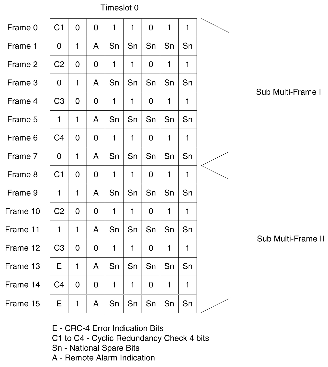
CRC-4
A CRC-4 multi-frame structure is shown in Figure C-7. CRC-4 uses timeslot 0 primarily to aid in frame alignment validation but can be used to monitor error performance as well. A CRC multi-frame consists of timeslot 0 information from 16 consecutive frames. Each CRC-4 multi-frame is divided into 2 eight-frame sub-multi-frames (SMF).
Bit 1 is used to carry 3 different pieces of information:
The Alarm Indication Signal is received in Channel 0, Bit 3 of the non-alignment frame. If this bit is set, it indicates a Remote Alarm Indication. As with the ANSI ATM, this condition is ignored.
Bits 2 through 8 follow the standard E1 frame structure.
If CRC-4 in on, the provisioned Si information is not used. Instead, bit 0 is used for CRC4 information, CRC4 error reporting, and for multiframe alignment (see Figure C-7).
Figure C-7 CRC-4 Multiframe Structure
ATM Mapping into E1
Data channels 1 – 15 and 17 - 31 carries the data for a single ATM channel, as shown in Figure C-8. Note that the ATM cell size does not map directly over the E1 frame format, so the ATM cell can start in any data channel. The data is octet-aligned.
Figure C-8 ATM Cell Mapping into E1 Frames

ATM Driver
The ATM driver is a software module, residing as part of the ATMANSI or ATMITU applications, that provides the code required to interface between the AATM hardware and the SSCOP layer and ATM Layer Management interfaces. The primary functions of the driver include:
E1 ATM Driver
The E1 ATM driver is a software module that provides the interface between the E1 ATM hardware, the SSCOP layer, and ATM Layer Management Module. The E1 ATM driver exists only in the ATMITU application. The basic structure is based upon the ANSI ATM driver present in the ATMANSI application. The primary changes to the existing ANSI ATM driver include:
SSCOP
The primary task of the SSCOP (Service Specific Connection Oriented Protocol) is to provide assured data delivery between AAL connection endpoints. The SSCOP is 1 of 2 parts (the other being the SSCF) of the Service Specific part of the SAAL layer (also known as the SSCS, the Service Specific Convergence Sublayer of the SAAL). The other part of the SAAL Layer is the CPCS (which was just mentioned in the ATM driver). Breaking the SSCS into 2 sublayers allows a common connection oriented protocol with error recovery (the SSCOP) to provide a generic reliable data transfer service for different AAL interfaces defined by different SSCF layers. The primary functions of the SSCOP layer include:
SSCF
The primary task of the SSCF (Service Specific Coordination Function) is to map the services provided by the lower layers of the SAAL to the needs of a specific higher layer user. For the ATM high-speed signaling link, the higher layer user is the MTP-3 protocol.
For an E1 ATM high-speed signaling link, the link proving default values are significantly different compared to an ANSI ATM high-speed signaling link. Table C-1 illustrates the different link proving values.
Table C-1 Link Proving Differences Between ITU and ANSI
| CHG-ATM-LPS Parameter Name |
Description |
E1 ATM Default Values |
ANSI ATM Default Values |
| N1 |
Number of PDUs sent during link proving |
1000 |
64552 |
| TmrT2 |
Time to attempt link proving |
30 sec |
120 sec |
| maxnrp |
Maximum number of retransmitted PDUs during proving |
0 |
1 |
| TmrT3 |
Time between proving PDUs |
925 sec |
925 sec |
The time required for normal ANSI proving is approximately 60 seconds (925 sec/pdu * 64552 PDUs = 60 seconds). This time is greater than TmrT2 value for an E1 ATM high-speed signaling link (30 seconds), so a link with E1 ATM defaults would have gone out of service before a link with ANSI ATM defaults finishes proving. Thus, great care must be taken to ensure that compatible proving numbers are assigned to a signaling link.
ATM and SAAL Layer Management Interfaces
The primary task of the ATM and SAAL layer management layers is to map requests and indications between the system management for the EAGLE and the individual ATM, AAL5CP, SSCOP, and SSCF layers. This functionality is actually achieved using two management modules, which both interface to the system management.
ATM Layer Management
ATM layer management is achieved with the ATMM (ATM layer management module). The ATMM provides a supporting role for system management functions which include fault, performance, configuration, security and resource management functions. It is the job of the system management to coordinate with different layers locally to perform all tasks associated with these functions. The ATMM entity uses two types of interactions with the ATM entity to perform its functions. The first type of interaction is for the exchange of info between the ATM and ATMM entity. The second type of interaction is for peer to peer communication between ATMM entities (between the two nodes on both ends of the high-speed signaling link). This second interaction is achieved by sending and receiving and processing OAM F5 cells in the ATM high-speed signaling link implementation. The primary functions provided by the ATMM for an ANSI ATM high-speed signaling link include:
Note:
The general ATMM layer is capable of performing performance management functionality. The ATMM layer implemented by ATM high-speed signaling link does not support this capability.
The primary functions provided by the ATMM for an E1 ATM high-speed signaling link include only OAM F5 fault management: loopback by OAM cells. All other forms of OAM F5 management and OAM F5 performance management are not supported.
SAAL Layer Management
The SAAL layer management includes interfaces to and from AAL5CP, SSCOP, SSCF, and system management. SAAL layer management supports the following functions: