5 Application Configuration
Configure the First NOAM NE and Server
- Resolve the Hostname to Get the HTTPD running.
Change Hostname from the default value using sudo:
- Edit
/etc/hostsfile.Note:
Remove any occurrence of “.” and the “.<availability zone>” name, such as “.novalocal” from the hostname that might have got appended.- Append the hostname to the IPv4 line
as,
“127.0.0.1 localhost localhost4 NOAM1” - Append the hostname to the IPv6 line as,
“::1
                                                localhost localhost6 NOAM1”
- Append the hostname to the IPv4 line
as,
- Edit
/etc/syconfig/network.- Change the “HOSTNAME=XXXX” line to the new
hostname.
“HOSTNAME=NOAM1” - Set the hostname on the command line:
$ sudo
                                                hostname NOAM1
- Change the “HOSTNAME=XXXX” line to the new
hostname.
- Reboot the VM.
$ sudo init 6
- Edit
- Establish a NOAM GUI session as the guiadmin user on the NOAM server by using the XMI IP address.
- In NOAM GUI, create the NOAM network element using the XML file.
- Navigate to .
- Click Browse and type the pathname of the NOAM network XML file.
- Click Upload File to upload the XML file. See the examples in Sample Network Element and Hardware Profiles and configure the NOAM network element.
- Once the data has been uploaded, you should see a tabs display with
the name of your network element. Click on this tab which describes
the individual networks that are now configured.

- In NOAM GUI, map services to networks.
- Navigate to .
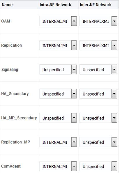
- Click Edit and set the services
as shown in the table below:
Table 5-1 Network Services
Name Intra-NE Network Inter-NE Network OAM <IMI Network> <XMI Network> Replication <IMI Network> <XMI Network> Signaling Unspecified Unspecified HA_Secondary Unspecified Unspecified HA_MP_Secondary Unspecified Unspecified Replication_MP <IMI Network> Unspecified ComAgent <IMI Network> Unspecified For example, if your IMI network is named IMI and your XMI network is named XMI, the configuration of services appears as shown below:
- Click OK to apply the Service-to-Network selections. Dismiss any possible popup notifications.
- In NOAM GUI, insert the first NOAM VM.
- Navigate to .
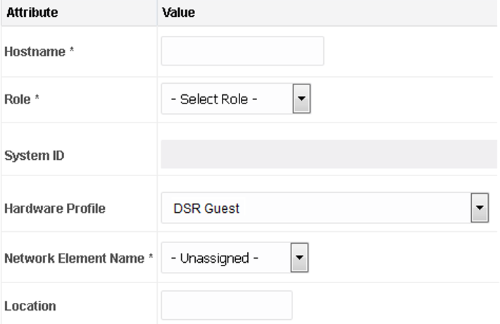
- Click Insert to insert the new
NOAM server into servers table (the first or server).
- Fill in the fields as follows:
Hostname: <Hostname>
Role: NETWORK OAM&P
System ID: <Site System ID>
Hardware Profile: DSR Guest
Network Element Name: [Select NE from drop-down list]
The network interface fields are now available with selection choices based on the chosen hardware profile and network element.

- Fill in the server IP addresses for the XMI network. Select ethX for the interface. Leave the VLAN checkbox unchecked.
- Fill in the server IP addresses for the IMI network. Select ethX for the interface. Leave the VLAN checkbox unchecked.
- Add the following NTP servers:
Table 5-2 NTP Servers
NTP Server Preferred? Valid NTP Server Yes Valid NTP Server No Valid NTP Server No - Click OK after entering the
server data.
Note:
Properly configure the NTP on the controller node to reference lower stratum NTP servers.
- In NOAM GUI, export the initial configuration.
- Navigate to .
- From the GUI screen, select the NOAM server and click Export to generate the initial configuration data for that server. Go to the Info tab to confirm the file has been created.
- In the NOAM Server, copy configuration file to first NOAM
server.
- Log in as an admusr, to obtain a terminal window to the first NOAM server.
- Run the following step if the set up is IPv6:
- Run the following
command:
sudo rm -f /etc/sysconfig/network-scripts/ifcfg-eth* - Copy the configuration file created in the
previous step from the
/var/TKLC/db/filemgmtdirectory on the first NOAM to the/var/tmpdirectory. The configuration file consists a filename such as:TKLCConfigData.<hostname>. - Following is an example:
sudo scp /var/TKLC/db/filemgmt/TKLCConfigData.<hostname>.sh admusr@<ipaddr>:/var/TKLC/db/filemgmt/TKLCConfigData.sh - Run the following
command:
- Run the following step for IPv4 set up:
- Copy the configuration file created in the
previous step from the
/var/TKLC/db/filemgmtdirectory on the first NOAM to the/var/tmpdirectory. The configuration file consists a filename such as:TKLCConfigData.sh. - Following is an
example:
$ sudo cp /var/TKLC/db/filemgmt/TKLCConfigData.<hostname>.sh /var/tmp/TKLCConfigData.sh
- Copy the configuration file created in the
previous step from the
- In first NOAM Server, wait for configuration to complete.
The automatic configuration daemon looks for the file named
TKLCConfigData.shin the/var/tmpdirectory, implements the configuration in the file, and prompts the user to reboot the server.If you are on the console, wait to be prompted to reboot the server, but do not reboot the server, it is rebooted later in this procedure.
Verify the script completed successfully by checking the following file.$ sudo cat /var/TKLC/appw/logs/Process/install.logNote:
Ignore the warning about removing the USB key since no USB key is present. No response occurs until the reboot prompt is issued. - In first NOAM Server, set the time zone (Optional) and reboot
the server.
To change the system time zone, from the command line prompt, run
set_ini_tz.pl. The following command example uses the America/New_York time zone.Replace, as appropriate, with the time zone you have selected for this installation. For a full list of valid time zones, see List of Frequently Used Time Zones.
Wait for server to reboot.$ sudo /usr/TKLC/appworks/bin/set_ini_tz.pl "America/New_York" >/dev/null 2>&1 $ date $ sudo init 6 - In first NOAM Server, verify server health.
- Log in to the NOAM1 as the admusr user.
- Run the following command as
admusr on the first NOAM server and
ensure no errors are
returned:
$ sudo syscheck
Running modules in class hardware
        OK
Running modules in class disk
        OK
Running modules in class net
        OK
Running modules in class system
        OK
Running modules in class proc
        OK
LOG LOCATION: /var/TKLC/log/syscheck/fail_log
Configure the NOAM Server Group
This procedure configures the NOAM server group.
- Log in to NOAM GUI.
- Establish a GUI session on the first NOAM server by using
the XMI IP address of the first NOAM server. Open the web browser and
type
http://<NO1_XMI_IP_Address>as the URL. - Log in as the guiadmin user. If prompted by a security warming, click Continue to this Website to proceed.
- Establish a GUI session on the first NOAM server by using
the XMI IP address of the first NOAM server. Open the web browser and
type
- In NOAM GUI, enter NOAM server group data.
- Navigate to .
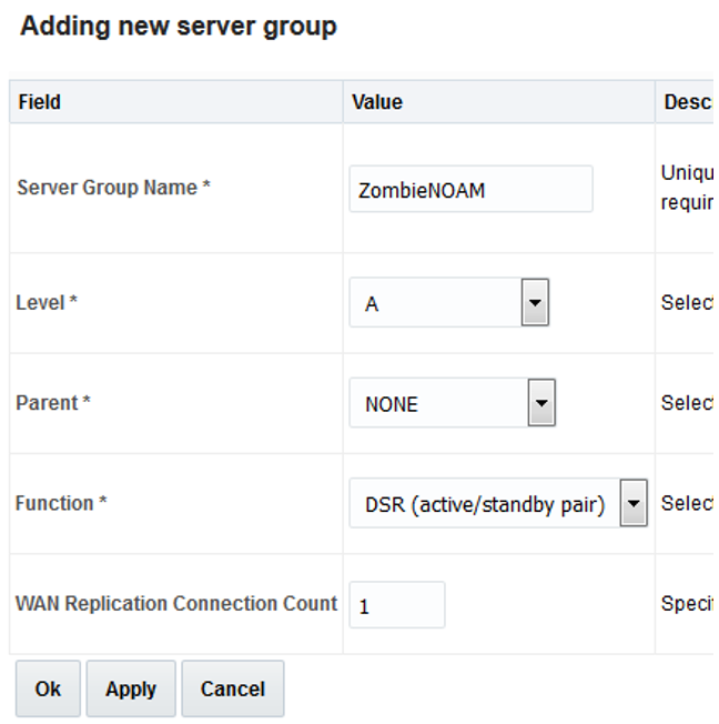
- Click Insert and fill in the following
fields:
Server Group Name: [Enter Server Group Name]
Level: A
Parent: None
Function: DSR (Active/Standby Pair)
WAN Replication Connection Count:Use Default Value
- Click OK when all fields are filled.
- In NOAM GUI, edit the NOAM server group.
- Navigate to .
- Select the new server group and click
Edit.
Select the network element that represents the NOAM.

- In the portion of the screen that lists the servers for the server group, find the NOAM server being configured. Mark the Include in SG checkbox.
- Leave the other box unchecked.
- Click OK.
- In NOAM server, verify NOAM VM role.
From console window of the first NOAM VM, run the
ha.mystatecommand to verify the DbReplication and VIP items under the resourceId column has a value of Active under the role column.You may have to wait a few minutes for it to be in that state.
Example:

- In NOAM GUI, restart first NOAM VM.
- Navigate to .
- Select the first NOAM server. Click Restart.
- Click OK on the confirmation screen and wait for restart to complete.
- In NOAM server, set sysmetric thresholds for VMs.
Note:
These commands disable the message rate threshold alarms.From console window of the first NOAM VM, run theisetcommands as admusr:
Verify, if the correct value was configured.$ sudo iset -feventNumber='-1' SysMetricThreshold where "metricId='RoutingMsgRate' and function='DIAM'" $ sudo iset -feventNumber='-1' SysMetricThreshold where "metricId='RxRbarMsgRate' and function='RBAR'" $ sudo iset -feventNumber='-1' SysMetricThreshold where "metricId='RxFabrMsgRate' and function='FABR'"Example:$ sudo iqt SysMetricThreshold | grep RxFabrIngressMsgRateRxFabrMsgRate FABR *C RunningAvg -1 38000 36000 3000 RxFabrMsgRate FABR ** RunningAvg -1 32000 28000 3000 RxFabrMsgRate FABR -* RunningAvg -1 2400 20000 3000
Configure the Second NOAM Server
- Log in to NOAM GUI.
- If not already done, establish a GUI session on the
first NOAM server by using the XMI IP address of the first NOAM
server. Open the web browser and type
http://<NO1_XMI_IP_Address>as the URL. - Log in as the guiadmin user.
- If not already done, establish a GUI session on the
first NOAM server by using the XMI IP address of the first NOAM
server. Open the web browser and type
- In NOAM GUI, insert the second NOAM VM.
- Navigate to .
- Click Insert to insert the new NOAM server into servers table (the first or server).
- Fill in the fields as follows:
Hostname: <Hostname>
Role: NETWORK OAM&P
System ID: <Site System ID>
Hardware Profile: DSR Guest
Network Element Name: [Choose NE list]
The network interface fields are now available with selection choices based on the chosen hardware profile and network element.

- Fill in the server IP addresses for the XMI network. Select ethX for the interface. Leave the VLAN checkbox unmarked.
- Fill in the server IP addresses for the IMI network. Select ethX for the interface. Leave the VLAN checkbox unmarked.
- Add the following NTP servers:
Table 5-3 NTP Server
NTP Server Preferred? Valid NTP Server Yes Valid NTP Server No Valid NTP Server No - Click OK after entering the
server data.
Note:
Properly configure the NTP on the controller node to reference lower stratum NTP servers.
- In NOAM GUI, export the initial configuration.
- Navigate to .
- From the GUI screen, select server just configured and click Export to generate the initial configuration data for that server. Go to the Info tab to confirm the file has been created.
- In the first NOAM server, copy configuration file to second NOAM
server.
- Log in as an admusr to obtain a terminal session to the first NOAM server.
- Run the following step to set up IPv6:
- Log in as an admusr user to the NO1 shell and issue the following command:
udo scp /var/TKLC/db/filemgmt/TKLCConfigData.<hostname>.sh admusr@<ipaddr>:/var/TKLC/db/filemgmt/TKLCConfigData.shNote:
ipaddr is the IP address of NOAM2 assigned to its ethx interface associated with the xmi network.- Obtain a terminal session to the second NOAM as an admusr.
- Run the following commands on NOAM 2
shell:
$ sudo rm -f /etc/sysconfig/network-scripts/ifcfg-eth*sudo cp/var/TKLC/db/filemgmt/TKLCConfigData.sh /var/tmp/TKLCConfigData.sh
- Run the following command to set up
IPv4:
$ sudo scp /var/TKLC/db/filemgmt/TKLCConfigData.<hostname>.sh admusr@<ipaddr>:/var/tmp/TKLCConfigData.sh
- In second NOAM server, wait for configuration to complete.
- Obtain a terminal session to the second NOAM as the
admusr user.
The automatic configuration daemon looks for the file named
TKLCConfigData.shin the/var/tmpdirectory, implements the configuration in the file, and prompts the user to reboot the server. - If you are on the console, wait to be prompted to reboot the server, but do not reboot the server, it is rebooted later in this procedure.
- Verify script completed successfully by checking the following
file.
$ sudo cat /var/TKLC/appw/logs/Process/install.logNote:
Ignore the warning about removing the USB key since no USB key is present.
- Obtain a terminal session to the second NOAM as the
admusr user.
- In second NOAM server, reboot the server.
Obtain a terminal session to the second NOAM as the admusr user.
Wait for server to reboot.$ sudo init 6 - In second NOAM server, verify server health.
- Log in to the NOAM2 as admusr and wait.
- Run the following command as super-user on the second
NO server and make sure no errors are
returned:
$ sudo syscheck
Running modules in class hardware...
        OK
Running modules in class disk...
        OK
Running modules in class net...
        OK
Running modules in class system...
        OK
Running modules in class proc...
        OK
LOG LOCATION: /var/TKLC/log/syscheck/fail_log
Complete the NOAM Server Group Configuration
This procedure configures the NOAM Server Group.
- In NOAM GUI, edit the NOAM Server Group Data.
- From the GUI session on the first NOAM server, navigate to .
- Select the NOAM server group and click Edit.
- Add the second NOAM server to the server group by marking the
Include in SG checkbox for the second NOAM
server. Then, click Apply.

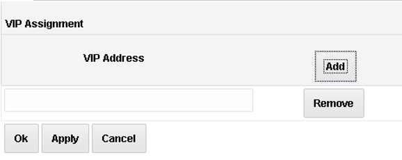
- Click Add to add a NOAM VIP. Type the VIP Address
and click OK.
- Establish a GUI session on the NOAM by using the NOAM VIP address. log in as the guiadmin user.
- Wait for the alarm ID
10200 Remote Database re-initialization in
                        progress
to be cleared before proceeding to . - In NOAM GUI, restart the second NOAM VM.
- Navigate to and select the second NOAM server.
- Click Restart.
- Click OK on the confirmation screen.
Wait approximately 3-5 minutes before proceeding to allow the system to stabilize indicated by having the Appl State as Enabled.
Note:
In case you receive alarm,10073 – Server group max allowed HA Role warning, perform the following:- Log in to the SO GUI and navigate to the .
- Click Edit and change the Max Allowed HA role of the current Standby SOAM to Active.
Note:
If this deployment contains SDS, SDS can now be installed. Refer to document referenced in SDS SW Installation and Configuration Guide.
Configure the DR NOAM NE and Server
This procedure configures the first DR NOAM VM. This is an optional procedure.
- Establish a GUI session on the primary NOAM server by using the XMI VIP IP address.
- In primary NOAM VIP GUI, create the DR NOAM network element using the XML
file.
- Navigate to .
- Click Browse and type the pathname to the NOAM network XML file.
- Click Upload File to upload the XML
file.
See the examples in Sample Network Element and Hardware Profiles and configure the NOAM network element.
- A tab displaying the name of your network element will
appear. Click on the tab, which describes the individual networks that
are now configured.

- In primary NOAM VIP GUI, insert the first DR NOAM VM.
- Navigate to .
- Click Insert to insert the new NOAM server into servers table (the first or server).
- Fill in the fields as follows:
Hostname: <Hostname>
Role: NETWORK OAM&P
System ID: <Site System ID>
Hardware Profile: DSR Guest
Network Element Name: [Select NE from list]
The network interface fields are now available with selection choices based on the chosen hardware profile and network element.
- Fill in the server IP addresses for the XMI network. Select ethX for the interface. Leave the VLAN checkbox unchecked.
- Fill in the server IP addresses for the IMI network. Select ethX for the interface. Leave the VLAN checkbox unchecked.
- Add the following NTP servers:
Table 5-4 NTP Servers
NTP Server Preferred? Valid NTP Server Yes Valid NTP Server No Valid NTP Server No - Click OK after entering the server
data.
Note:
Properly configure the NTP on the controller node to reference lower stratum NTP servers.
- In primary NOAM VIP GUI, export the initial configuration.
- Navigate to .
- From the GUI screen, select the NOAM server and click Export to generate the initial configuration data for that server. Go to the Info tab to confirm the file has been created.
- In the primary NOAM server, copy configuration file from the first
primary NOAM server to the first NOAM at the DRNOAM server.
- Log in as an admusr to obtain a terminal window to the Primary NOAM server.
- Run the following step to set up IPv6
- Copy the configuration file created in the previous
step from the
/var/TKLC/db/filemgmtdirectory on the first NOAM at the DRNOAM server in the/var/TKLC/db/filemgmtdirectory. The configuration file consists a filename likeTKLCConfigData.<hostname> - Following is an example:
sudo scp /var/TKLC/db/filemgmt/TKLCConfigData.<hostname>.sh admusr@<ipaddr>:/var/TKLC/db/filemgmt/TKLCConfigData.shNote:
ipaddr is the IP address of DR NOAM assigned to its ethx interface associated with the XMI network.- Obtain a terminal session to the first NOAM at DRNOAM as the admusr.
- Run the following commands on the first Noam at
DRNOAM
shell.
$ sudo rm -f /etc/sysconfig/network-scripts/ifcfg-eth*$ sudo cp /var/TKLC/db/filemgmt/TKLCConfigData.sh /var/tmp/TKLCConfigData.sh
- Copy the configuration file created in the previous
step from the
- Run the following step to set up IPv4:
- Copy the configuration file created in the previous
step from the
/var/TKLC/db/filemgmtdirectory on the 1 st NOAM at the DRNOAM server in the/var/tmpdirectory. - The configuration file consists a filename such as:
TKLCConfigData.<hostname>.sh. - Following is an
example:
sudo scp /var/TKLC/db/filemgmt/TKLCConfigData.<hostname>.sh admusr@<ippadr>:/var/tmp/TKLCConfigData.sh
- Copy the configuration file created in the previous
step from the
- In first DR NOAM server, wait for configuration to complete.
The automatic configuration daemon looks for the file named
TKLCConfigData.shin the/var/tmpdirectory, implements the configuration in the file, and prompts the user to reboot the server.If you are on the console, wait to be prompted to reboot the server, but do not reboot the server, it is rebooted later in this procedure.
Verify the script completed successfully by checking the following file.$ sudo cat /var/TKLC/appw/logs/Process/install.logNote:
Ignore the warning about removing the USB key since no USB key is present. No response occurs until the reboot prompt is issued. - In first DR NOAM server, reboot the server.
Obtain a terminal window to the first DR NOAM server, logging in as the admusr user.Wait for server to reboot.
$ sudo init 6 - In first DR NOAM server, verify server health.
- Obtain a terminal window to the first DR NOAM server, logging in as the admusr user.
- Run the following command as admusr
and ensure that no errors are
returned:
$ sudo syscheck
Running modules in class hardware...
        OK
Running modules in class disk...
        OK
Running modules in class net...
        OK
Running modules in class system...
        OK
Running modules in class proc...
        OK
LOG LOCATION: /var/TKLC/log/syscheck/fail_log
Configure the DR NOAM Server Group
This procedure configures the DR NOAM server group. This is an optional procedure.
- Log in to primary NOAM VIP GUI.
- Establish a GUI session on the primary NOAM server by using
the XMI IP address of the first NOAM server. Open the web browser and
type
http://<NO1_XMI_IP_Address>as the URL. - Log in as the guiadmin user. If prompted by a security warming, click Continue to this Website to proceed.
- Establish a GUI session on the primary NOAM server by using
the XMI IP address of the first NOAM server. Open the web browser and
type
- In primary NOAM VIP GUI, enter DR NOAM server group data.
- Using the GUI session on the primary NOAM server, navigate to .
- Click Insert and fill in the following
fields:
Server Group Name: [Enter Server Group Name]
Level: A
Parent: None
Function: DSR (Active/Standby Pair)
WAN Replication Connection Count:Use Default Value
- Click OK when all fields are filled.
- In primary NOAM VIP GUI, edit the DR NOAM server group.
- Navigate to .
- Select the new server group and click Edit.
- Select the network element that represents the DR NOAM.
- In the portion of the screen that lists the servers for the server group, find the NOAM server being configured. Mark the Include in SG checkbox.
- Leave other boxes unchecked.
- Click OK.
- In primary NOAM VIP GUI, restart first DR NOAM VM.
- From the NOAM GUI, navigate to .
- Select the first NOAM server. Click Restart.
- Click OK on the confirmation screen and wait for restart to complete.
Configure the Second DR NOAM Server
This procedure configures the second DR NOAM server. This is an optional procedure.
- Log in to primary NOAM VIP GUI.
- If not already done, establish a GUI session on the first
NOAM server by using the XMI IP address of the first NOAM server. Open
the web browser and type
http://<NOAM1_XMI_IP_Address>as the URL. - Log in as the guiadmin user.
- If not already done, establish a GUI session on the first
NOAM server by using the XMI IP address of the first NOAM server. Open
the web browser and type
- In primary NOAM VIP GUI, insert the second DR NOAM VM.
- Navigate to .
- Click Insert to insert the new NOAM server into servers table (the first or second server).
- Fill in the fields as follows:
Hostname: <Hostname>
Role: NETWORK OAM&P
System ID: <Site System ID>
Hardware Profile: DSR Guest
Network Element Name: [Choose NE from list]
The network interface fields are now available with selection choices based on the chosen hardware profile and network element.
- Fill in the server IP addresses for the XMI network. Select ethX for the interface. Leave the VLAN checkbox unmarked.
- Fill in the server IP addresses for the IMI network. Select ethX for the interface. Leave the VLAN checkbox unmarked.
- Add the following NTP servers:
Table 5-5 NTP Servers
NTP Server Preferred? Valid NTP Server Yes Valid NTP Server No Valid NTP Server No - Click OK after entering the server
data.
Note:
Properly configure the NTP on the controller node to reference lower stratum NTP servers.
- In primary NOAM VIP GUI, export the initial configuration.
- Navigate to .
- From the GUI screen, select the server just configured and click Export to generate the initial configuration data for that server.
- Go to the Info tab to confirm the file has been created.
- In the primary NOAM, copy configuration file to second DR NOAM
server.
- log in as an admusr to obtain a terminal session to the primary NOAM server.
- Run the following step to set up IPv6:
- Copy the configuration file created in the previous
step from the
/var/TKLC/db/filemgmtdirectory on the second DR-NOAM server in the/var/TKLC/db/filemgmtdirectory. - The configuration file consists a filename such as:
TKLCConfigData.<hostname>.sh. - Following is an
example:
$ sudo scp /var/TKLC/db/filemgmt/TKLCConfigData.<hostname>.sh admusr@<ipaddr>:/var/TKLC/db/filemgmt/TKLCConfigData.sh - Obtain a terminal session to the second DRNOAM as an admusr.
- Run the following commands on second DRNOAM
shell:
$ sudo rm -f /etc/sysconfig/network-scripts/ifcfg-eth*sudo cp /var/TKLC/db/filemgmt/TKLCConfigData.sh /var/tmp/TKLCConfigData.sh
- Copy the configuration file created in the previous
step from the
- Run the following step to set up IPv4:
- Log in as the admusr user to the NOAM1 shell and issue the following command:
$ sudo scp /var/TKLC/db/filemgmt/TKLCConfigData.<hostname>.sh
admusr@<ipaddr>:/var/tmp/TKLCConfigData.sh
Note:
ipaddris the IP address of DR NOAM assigned to itsethxinterface associated with the XMI network.
- In second DR NOAM server, wait for configuration to complete.
- Obtain a terminal session to the second DR NOAM as the
admusr user.
The automatic configuration daemon looks for the file named
TKLCConfigData.shin the/var/tmpdirectory, implements the configuration in the file, and prompts the user to reboot the server. - If you are on the console, wait to be prompted to reboot the server, but do not reboot the server, it is rebooted later in this procedure.
- Verify script completed successfully by checking the following
file.
$ sudo cat /var/TKLC/appw/logs/Process/install.logNote:
Ignore the warning about removing the USB key since no USB key is present.
- Obtain a terminal session to the second DR NOAM as the
admusr user.
- In second DR NOAM server, reboot the server.
Obtain a terminal session to the second DR NOAM as the admusr user.Wait for server to reboot.
$ sudo init 6 - In second DR NO server, verify server health.
- Obtain a terminal session to the second DR NOAM as the admusr user.
- Run the following command as super-user and make sure no
errors are
returned:
$ sudo syscheck
Running modules in class hardware...
        OK
Running modules in class disk...
        OK
Running modules in class net...
        OK
Running modules in class system...
        OK
Running modules in class proc...
        OK
LOG LOCATION: /var/TKLC/log/syscheck/fail_log
Complete Configuring the DR NOAM Server Group
This procedure finishes configuring the DR NOAM Server Group. This is an optional procedure.
- In primary NOAM VIP GUI, edit the DR NOAM server group data.
- From the GUI session on the primary NOAM server, navigate to .
- Select the NOAM server group and click Edit.
- Add the second NOAM server to the server group by marking the Include in SG checkbox for the second NOAM server. Then, click Apply.
- Click Add to add an NOAM VIP. Type the
VIP Address and click
OK.

- Establish a GUI session on the primary NOAM by using the NOAM VIP address. log in as the guiadmin user.
- In primary NOAM VIP GUI, wait for the alarm
ID 10200 Remote Database
                        re-initialization
in progress to be cleared before proceeding to . - In primary NOAM VIP GUI, restart second DR NOAM VM.
- Navigate to and select the second DR NOAM server.
- Click Restart.
- Select OK on the confirmation screen.
Wait approximately 3-5 minutes before proceeding to allow the system to stabilize indicated by having the Appl State as Enabled.
- In primary NOAM, modify DSR OAM process.
Establish an SSH session to the primary NOAM, log in as the admusr user. Run the following commands:
- Retrieve the cluster ID of the
DR-NOAM:
$ sudo iqt –NodeID TopologyMapping where "NodeID='<DR_NOAM_Host_Name>' " Server_ID NodeID ClusterID 1 Oahu-DSR-DR-NOAM-2 A1055 - Run the following command to start the DSR OAM process on
the
DR‑NOAM.
$ echo "<clusterID>|DSROAM_Proc|Yes" | iload –ha –xun -fcluster –fresource –foptional HaClusterResourceCfg
- Retrieve the cluster ID of the
DR-NOAM:
Configure the SOAM NE
This procedure configures the SOAM network element.
- If needed, establish a GUI session on the NOAM by using the NOAM VIP address. log in as the guiadmin user.
- In primary NOAM VIP GUI, create the SOAM network element using an
XML file.
Ensure to have an SOAM network element XML file available on the PC running the web browser. The SOAM network element XML file is similar to what was created and used in Configure the First NOAM NE and Server, but defines the SOAM network element.
Refer to Sample Network Element and Hardware Profiles for a sample network element xml file.
- Navigate to .
- Click Browse and type the path and name of the SOAM network XML file.
- Click Upload to upload the XML file and configure the SOAM network element.
Configure the SOAM Servers
- If needed, establish a GUI session on the NOAM by using the NOAM VIP address. log in as the guiadmin user.
- In primary NOAM VIP GUI, insert the first SOAM server.
- Navigate to .
- Click Insert to insert the new SOAM server into servers table.
- Fill in the fields as follows:
Hostname: <SO1-Hostname>
Role: SYSTEM OAM
System ID: <Site System ID>
Hardware Profile: DSR Guest
Network Element Name: [Choose NE from list]
The network interface fields are now available with selection choices based on the chosen hardware profile and network element.
- Fill in the server IP addresses for the XMI network. Select ethX for the interface. Leave the VLAN checkbox unmarked.
- Fill in the server IP addresses for the IMI network. Select ethX for the interface. Leave the VLAN checkbox unmarked.
- Add the following NTP servers:
Table 5-6 NTP Servers
NTP Server Preferred? Valid NTP Server Yes Valid NTP Server No Valid NTP Server No - Click OK when you have completed entering the
server data.
Note:
Properly configure the NTP on the controller node to reference lower stratum NTP servers.
- In primary NOAM VIP GUI, export the initial configuration.
- Navigate to .
- From the GUI screen, select the desired server and click Export to generate the initial configuration data for that server.
- Go to the Info tab to confirm the file has been created.
- In the primary NOAM, copy configuration file to the first SOAM
server. Log in as an admusr user to the NOAM1 shell
and issue the commands:
- Run the following steps to set up
IPv6:
$ sudo scp /var/TKLC/db/filemgmt/TKLCConfigData.<hostname>.sh admusr@<ipaddr>:/var/TKLC/db/filemgmt/TKLCConfigData.shNote:
ipaddr is the IP address of first SOAM assigned to its ethx interface associated with the xmi network.- Obtain a terminal session to the first SOAM as the admusr.
- Run the following commands on first SOAM
shell:
$ sudo rm -f /etc/sysconfig/network-scripts/ifcfg-eth*sudo cp /var/TKLC/db/filemgmt/TKLCConfigData.sh /var/tmp/TKLCConfigData.sh
- Run the following command to set up
IPv4:
$ sudo scp /var/TKLC/db/filemgmt/TKLCConfigData.<hostname>.sh admusr@<ipaddr>:/var/tmp/TKLCConfigData.sh
- Run the following steps to set up
IPv6:
- In the first SOAM server, wait for configuration to complete.
- Obtain a terminal session on the first SOAM as the
admusr user.
The automatic configuration daemon looks for the file named
TKLCConfigData.shin the/var/tmpdirectory, implements the configuration in the file, and prompts the user to reboot the server. - If you are on the console wait to be prompted to reboot the server, but do not reboot the server, it is rebooted later in this procedure.
- Verify script completed successfully by checking the following
file.
$ sudo cat /var/TKLC/appw/logs/Process/install.logNote:
Ignore the warning about removing the USB key since no USB key is present.
- Obtain a terminal session on the first SOAM as the
admusr user.
- In first SOAM server, reboot the server.
Obtain a terminal session to the first SOAM as the admusr user.Wait for server to reboot.
$ sudo init 6 - In first SOAM server, verify server health.
- After the system reboots, log in again as the admusr user.
- Run the following command and make sure that no errors
are
returned:
# sudo syscheck
Running modules in class hardware...
        OK
Running modules in class disk...
        OK
Running modules in class net...
        OK
Running modules in class system...
        OK
Running modules in class proc...
        OK
LOG LOCATION: /var/TKLC/log/syscheck/fail_log
- Repeat steps 1 through 7 to insert and configure the second
SOAM server.
- Run the following steps to set up
IPv6:
$ sudo scp /var/TKLC/db/filemgmt/TKLCConfigData.<hostname>.sh admusr@<ipaddr>:/var/TKLC/db/filemgmt/TKLCConfigData.shNote:
ipaddr is the IP address of second SOAM assigned to its ethx interface associated with the xmi network.- Obtain a terminal session to the second SOAM as the admusr.
- Run the following commands on second SOAM
shell.
$ sudo rm -f /etc/sysconfig/network-scripts/ifcfg-eth*sudo cp /var/TKLC/db/filemgmt/TKLCConfigData.sh /var/tmp/TKLCConfigData.sh
- Run the following command to set up
IPv4:
$ sudo scp /var/TKLC/db/filemgmt/TKLCConfigData.<hostname>.sh admusr@:/var/tmp/TKLCConfigData.sh - Wait approximately 5 minutes for the second SOAM
server to restart.
Note:
For DSR mated sites, repeat this step for additional or spare SOAM server.
- Run the following steps to set up
IPv6:
Configure the SOAM Server Group
This procedure configures the SOAM server group.
- In primary NOAM VIP GUI, enter SOAM server group data.
- From the GUI session on the NOAM VIP address, navigate to .
- Click Insert and add the SOAM server group name
along with the values for the following fields:
Name: [Enter Server Group Name]
Level: B
Parent: [Select the NOAM Server Group]
Function: DSR (Active/Standby Pair)
WAN Replication Connection Count: Use Default Value
- Click OK when all fields are filled.
Note:
For DSR mated sites, repeat this step for additional SOAM server groups where the preferred SOAM spares may be entered before the active/standby SOAMs.
- In primary NOAM VIP GUI, edit the SOAM server group and add VIP.
- Navigate to .
- Select the new SOAM server group and click Edit.
- Add both SOAM servers to the server group primary site by marking the Include in SG checkbox.
- Click Apply.
- In primary NOAM VIP GUI, add the SOAM VIP.
- Navigate to .
- Select the new SOAM server group and click Edit.
- Click Add to add a SOAM VIP. Type the VIP Address and click OK.
- In primary NOAM VIP GUI, edit the SOAM server group and add
preferred spares for site redundancy.
This is an optional step.
If the two-site redundancy feature is wanted for the SOAM server group, add an SOAM server located in its server group secondary site by marking the Include in SG and Preferred Spare checkboxes.

For more information about server group secondary site or site redundancy, see the Terminology section. - In primary NOAM VIP GUI, edit the SOAM server group and add additional SOAM
VIPs.
This is an optional step.
- Click Add to add SOAM VIPs.
- Type the VIP Address and click
OK.
Note:
Additional SOAM VIPs only apply to SOAM server groups with preferred spare SOAMs.
- In primary NOAM VIP GUI, wait for replication.
After replication, the server status should be active. Navigate to .
Look for the alarm IDNote:
This may take up to 5 minutes while the servers figure out master/slave relationship.10200 Remote Database re-initialization in progressto be cleared before proceeding. Navigate to . - In primary NOAM VIP GUI, restart first SOAM server.
- From the NOAM GUI, navigate to and select the first SOAM server.
- Click Restart.
- Click OK on the confirmation screen.
Wait for restart to complete. Wait for the Appl State to change to Enabled, and all other columns to Norm.
Note:
Repeat this step for the second SOAM.
- In primary NOAM VIP GUI, restart all preferred spare SOAM servers.
This is an optional step.
- If additional preferred spare servers are configured for secondary sites, navigate to and select all the Preferred Spare SOAM servers.
- Click Restart and then, click
OK to the confirmation popup.
Wait for the Appl State to change to Enabled and all other columns to change to Norm.
Activate PCA/DCA
This procedure activates PCA/DCA. This is applicable only for PCA and DCA.
- Activate PCA feature.
If you are installing PCA, run the applicable procedures (Added SOAM site activation or complete system activation) of the DSR PCA Activation Guide to activate PCA.
Note:
- If not all SOAM sites are ready at this point, then you should repeat activation for each new SOAM site that comes online.
- Ignore steps to restart DA-MPs and SBRs that have yet to be configured.
- Activate DCA feature.
If you are installing PCA, run DCA Framework and Application Activation and Deactivation Guide to activate the DCA framework and feature.
Note:
- If not all SOAM sites are ready at this point, then you should repeat activation for each new SOAM site that comes online.
- Ignore steps to restart DA-MPs and SBRs that have yet to be configured.
Configure the MP Virtual Machines
This procedure configures MP VMs (IPFE, SBR, DA-MP, and vSTP).
- If needed, establish a GUI session on the NOAM by using the NOAM VIP address. log in as the guiadmin user.
- In primary NOAM VIP GUI, navigate to the signaling network configuration
screen.
- Navigate to .
- Navigate to the SO Network Element tab under which the MPs are to be configured.
- Click Insert in the lower left corner.
- In primary NOAM VIP GUI, add signaling networks.
The following screen displays.
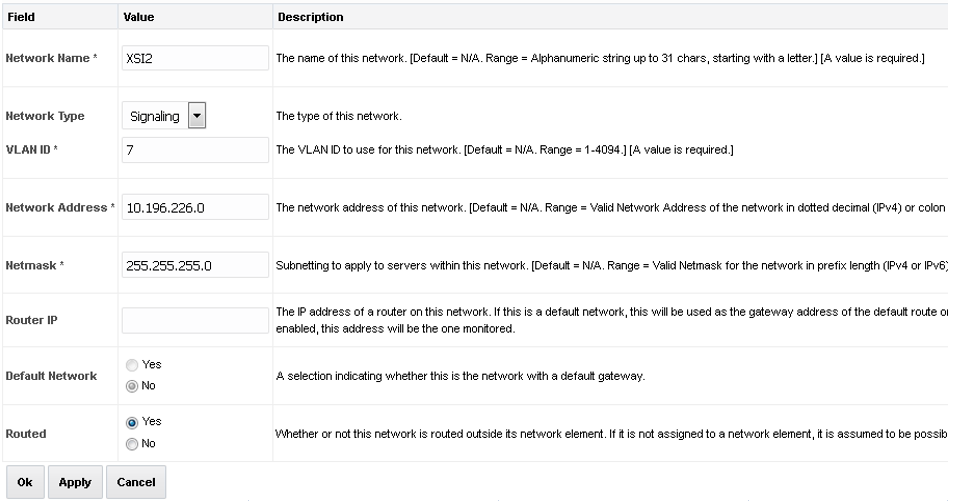
- Type the Network Name, Network Type, VLAN ID,
Network Address, Netmask, and Router IP that
matches the signaling network.
Note:
Even if the network does not use VLAN tagging, you should type the correct VLAN ID here as indicated by the NAPD.- Select Signaling for Network Type.
- Select No for Default Network.
- Select Yes for Routable.
- If you are finished adding signaling networks, click OK. To save this signaling network and repeat this step to enter additional signaling networks, click Apply .
- Type the Network Name, Network Type, VLAN ID,
Network Address, Netmask, and Router IP that
matches the signaling network.
- In primary NOAM VIP GUI, navigate to signaling network configuration screen.
Note:
Run this step only if you are defining a separate, dedicated network for SBR Replication. This step is applicable only for PCA or DCA.- Navigate to .
- Click Insert in the lower left corner.
- In primary NOAM VIP GUI, define SBR DB replication network.
Note:
Run this step only if you are defining a separate, dedicated network for SBR replication. This is applicable only for PCA.- Type the Network Name, Network Type, VLAN
ID, Network Address, Netmask, and Router IP
that matches the SBR DB replication network.
Note:
Even if the network does not use VLAN tagging, you should type the correct VLAN ID here as indicated by the NAPD.- Select No for Default Network.
- Select Yes for Routable.
- If you are finished adding signaling networks, click OK. To save this signaling network and repeat this step to enter additional signaling networks, click Apply .
- Type the Network Name, Network Type, VLAN
ID, Network Address, Netmask, and Router IP
that matches the SBR DB replication network.
- In primary NOAM VIP GUI, perform additional service to networks
mapping.
Note:
Run this step only if you are defining a separate, dedicated network for SBR replication. This is only applicable to PCA.- Navigate to .
- Click Edit.
- Set the services using one of the following scenarios.
- If the dual-path HA configuration is required:
For HA_MP_Secondary, Oracle recommends the inter-NE network is set as the XMI network and intra-NE network is set as the IMI network. If the primary interface (Replication_MP) SBR DB Replication Network interface goes down, use the secondary network for sharing HA status to reduce the likelihood of a split brain. This leads to DSR mate isolation from the active SBR and results in traffic loss until SBR DB Replication Network is down.
Table 5-7 Replication Network
Name Intra-NE Network Inter-NE Network HA_MP_Secondary <IMI Network> <XMI Network> Replication_MP <IMI Network> <SBR DB Replication Network> ComAgent <IMI Network> <SBR DB Replication Network> 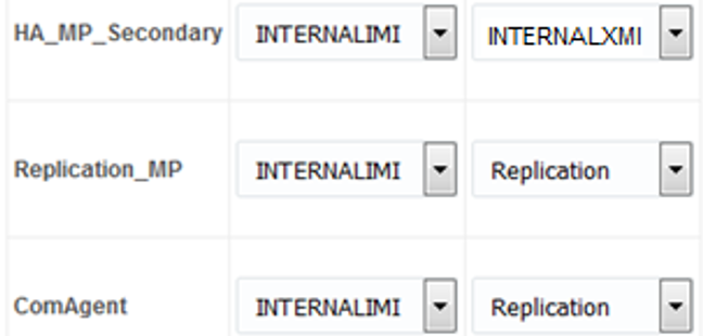
- If the dual-path HA configuration is not
required:
The intra-NE network is set as the IMI network and inter-NE network is set as the PCA replication network (configured in step 5. This may lead to a split database scenario in case the SBR DB Replication Network interface goes down. Due to this, an active SBR server in each site is in effect.
Table 5-8 Replication Network
Name Intra-NE Network Inter-NE Network HA_MP_Secondary <IMI Network> <SBR DB Replication Network> Replication_MP <IMI Network> <SBR DB Replication Network> ComAgent <IMI Network> <SBR DB Replication Network> 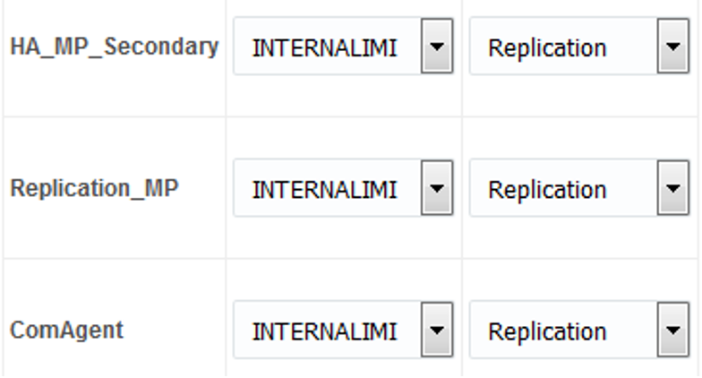
- If the dual-path HA configuration is required:
- Click OK to apply the Service-to-Network selections.
- In primary NOAM VIP GUI, insert the MP or IPFE server – Part 1.
- Navigate to .
- Click Insert to add the new MP or IPFE server into servers table.
- Fill in the following values:
Hostname: <Hostname>
Role: MP
System ID: <Site System ID>
Hardware Profile: DSR Guest
Network Element Name: [Choose NE from list]
- For the XMI network, type the MP's XMI IP address. Select the correct interface.
- Leave the VLAN checkbox unmarked.
- For the IMI network, type the MP's IMI IP address. Select the correct
interface.
- Leave the VLAN checkbox unmarked.
- For the Replication network, type the MP's XSI2 IP address. This is the IP address should be used from the name defined in step 5. This name would be the same name that is referred to as SBR DB Replication Network in step 6. Select the correct interface.
- For the XSI1 network, type the MP's XSI1 IP address. Select the correct
interface.
Note:
Leave the VLAN checkbox unmarked. - For the XSI2 network, type the MP's XSI2 IP address. Select the correct interface.
Note:
- Leave the VLAN checkbox unmarked.
- If more XSI networks are configured, follow the same method of entry as XSI1 and XSI2. All interfaces need to be added sequentially for any server.
- Add the following NTP servers:
Table 5-9 NTP Servers
NTP Server Preferred? Valid NTP Server Yes Valid NTP Server No Valid NTP Server No - Click OK when all fields are filled in to finish
MP server insertion.
Note:
Properly configure the NTP on the controller node to reference lower stratum NTP servers.
- In primary NOAM VIP GUI, export the initial configuration.
- Navigate to .
- From the GUI screen, select the server that was just configured and click Export to generate the initial configuration data for that server.
- Go to the Info tab to confirm the file has been created.
- In MP server, log into the MP.
Obtain a terminal window connection on the MP or IPFE server.
- In the primary NOAM VIP GUI, copy configuration file to MP or IPFE
server.
- From the active NOAM console, log in as the admusr user.
- Run the following steps to set up IPV6:
-
$ sudo scp /var/TKLC/db/filemgmt/TKLCConfigData.<hostname>.sh admusr@<ipaddr>:/var/TKLC/db/filemgmt/TKLCConfigData.shNote:
ipaddr is the IP address of MP/IPFE assigned to its ethx interface associated with the xmi network. - Obtain a terminal session to the MP or IPFE as an admusr.
- Run the following commands on MP or IPFE
shell:
$ sudo rm -f /etc/sysconfig/network-scripts/ifcfg-eth*$ sudo cp /var/TKLC/db/filemgmt/TKLCConfigData..sh/var/tmp/TKLCConfigData.sh
-
- Run the following command to set up
IPv4:
sudo scp /var/TKLC/db/filemgmt/TKLCConfigData.<hostname>.sh admusr@<ipaddr>:/var/TKLC/db/filemgmt/TKLCConfigData.shNote:
ipaddr is the IP address of NOAM2 assigned to its ethx interface associated with the xmi network.
- In MP server, wait for configuration to complete.
- Obtain a terminal session on the MP or IPFE as the
admusr user.
The automatic configuration daemon looks for the file named
TKLCConfigData.shin the/var/tmpdirectory, implements the configuration in the file, and prompts the user to reboot the server. - If you are on the console, wait to be prompted to reboot the server, but DO NOT reboot the server, it is rebooted later in this procedure.
- Verify script completed successfully by checking the following
file.
$ sudo cat /var/TKLC/appw/logs/Process/install.logNote:
Ignore the warning about removing the USB key since no USB key is present.
- Obtain a terminal session on the MP or IPFE as the
admusr user.
- In MP server, reboot the server.
Obtain a terminal session on the MP or IPFE as the admusr user.Wait for server to reboot.
$ sudo init 6 - In MP server, verify server health.
- After the reboot, log in as the admusr user.
- Run the following command as super-user on the server and
make sure that no errors are
returned:
$ sudo syscheck
Running modules in class hardware...
        OK
Running modules in class disk...
        OK
Running modules in class net...
        OK
Running modules in class system...
        OK
Running modules in class proc...
        OK
LOG LOCATION: /var/TKLC/log/syscheck/fail_log
- In MP server, delete auto-configured default route on MP and replace
it with a Network Route using the XMI Network.
Note:
This step is optional and should only be run to configure a default route on your MP that uses a signaling (XSI) network instead of the XMI network. Not running this step means a default route is not configurable on this MP and you have to create separate network routes for each signaling network destination.- Log into the MP as the admusr user. Alternatively, you can log into the VM’s console.
- Determine
<XMI_Gateway_IP>from your SO site network element information. - Gather the following items:
<NO_XMI_Network_Address>
<NO_XMI_Network_Netmask>
Note:
You can either consult the XML files you imported earlier, or go to the NO GUI and view these values from the menu. - Create network routes to the NO’s XMI (OAM) network.
- Navigate to NOAM VIP GUI ConfigurationNetworkingRoutes.
- Select the Specific MP.
- Click Insert.
- Enter details.
- Click OK.
- In MP console if sending SNMP traps from individual
servers, create host routes to customer SNMP trap destinations on the
XMI
network:
$ sudo /usr/TKLC/plat/bin/netAdm add --route=host -–address=<Customer_NMS_IP> --gateway=<MP_XMI_Gateway_IP_Address> - Route to
<MP_XMI_Interface>added. - Repeat for any existing customer NMS stations.
- Delete the existing default
route:
$ sudo /usr/TKLC/plat/bin/netAdm delete --route=default --gateway=<MP_XMI_Gateway_IP> --device=<MP_XMI_Interface>Route to
<MP_XMI_Interface>removed. - In MP console, ping active NO XMI IP address to verify
connectivity:
$ ping <ACTIVE_NO_XMI_IP_Address> PING 10.240.108.6 (10.240.108.6) 56(84) bytes of data. 64 bytes from 10.240.108.6: icmp_seq=1 ttl=64 time=0.342 ms 64 bytes from 10.240.108.6: icmp_seq=2 ttl=64 time=0.247 ms - In MP console, ping customer NMS
Station(s):
$ ping <Customer_NMS_IP> PING 172.4.116.8 (172.4.118.8) 56(84) bytes of data. 64 bytes from 172.4.116.8: icmp_seq=1 ttl=64 time=0.342 ms 64 bytes from 172.4.116.8: icmp_seq=2 ttl=64 time=0.247 ms - If you do not get a response, then verify your network
configuration. If you continue to get failures, then halt the
installation and contact Oracle customer support.
Note:
Repeat steps 7 through 14 for all remaining MP (SBR, DA-MP, IPFE and vSTP) servers.
Configure Places and Assign MP Servers to Places
- In primary NOAM VIP GUI, configure places.
- Establish a GUI session on the NOAM by using the XMI VIP address. log in as the guiadmin user.
- Navigate to .
- Click Insert.
- Fill in the fields as follows:
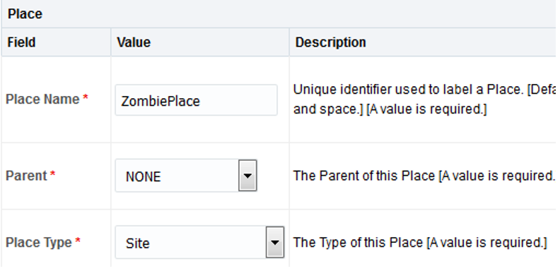
Place Name:<Site Name>
Parent: NONE
Place Type: Site
- Repeat this step for each of the PCA or DCA Places
(Sites) in the network.
See the Terminology section for more information on Sites & Places.
- In NOAM VIP GUI, assign MP server to places.
- Select the place configured in step 1 and click
Edit.
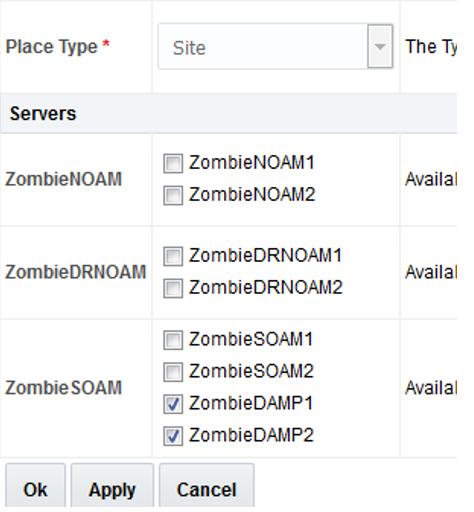
- Mark all the checkboxes for PCA/DCA DA-MP and SBR servers that are assigned to this place.
- Repeat this step for all other DA-MP or SBR servers you wish to
assign to places.
Note:
All DA-MPs and SBR servers must be added to the Site Place that corresponds to the physical location of the server.See the Terminology section for more information on Sites & Places.
- Select the place configured in step 1 and click
Edit.
Configure the MP Server Group(s) and Profiles
- In primary NOAM VIP GUI, enter MP Server Group Data applicable to all C
level servers (DAMP, IPFE, VSTP, SBRs).
- From the GUI session on the NOAM VIP address, navigate to .
- Click Insert and fill out the following
fields:
Server Group Name:[Server Group Name]
Level: C
Parent: [SOAM Server Group That is Parent To this MP]
Function: Select the Proper Function for this MP Server Group:
Table 5-10 MP Server Group
Server Group Function MPs Will Run Redundancy Model DSR (multi-active cluster) Diameter Relay and Application Services Multiple MPs Active per SG DSR (active-standby pair) Diameter Relay and Application Services 1 Active MP and 1 Standby MP/Per SG IP Front End IPFE application 1 Active MP Per SG SBR Policy and Charging Session/or Policy Binding Function/Universal SBR 1 Active MP, 1 Standby MP, 2 Optional Spare Per SG STP vSTP Multiple vSTP MP per SG STPService vSTP MP for the SMS Home Router feature. For vSTP:
If configuring only vSTP application, ignore all other IPFE configuration. Currently, there is no specific MP profile for vSTP MP.
Note:
- IPFE interaction with vSTP MP is not supported. There is no support of TSA/Auto selection for vSTP MPs.
- vSTP MP can co-exist with DA-MP under a SOAM but different server group.
- vSTP MP requires 8 GB of RAM.
- vSTP STPService MP must be configured if the SMS Home Router feature is activated by the user after the installation is complete.
For PCA application:
- Online Charging function(only)
At least one MP Server Group with the SBR function must be configured.
At least one MP Server Group with the DSR (multi-active cluster) function must be configured.
- Policy DRA function
At least two MP Server Groups with the SBR function must be configured. One stores session data and one stores binding data.
At least one MP Server Group with the DSR (multi-active cluster) function must be configured.
WAN Replication Connection Count:
For non-Policy and Charging SBR Server Groups: Default Value
For Policy and Charging Server Groups: 8
For the PCA application, the following types of MP Server Groups must be configured:
DA-MP (Function: DSR (multi-active cluster))
SBR (Function: SBR)
IPFE (Function: IP Front End)
- Click OK when all fields are filled.
- In primary NOAM VIP GUI, repeat step 1 for any remaining MP and IPFE server
groups you wish to create.
For instance, when installing an IPFE, you need to create an IP front end server group for each IPFE server.
- In primary NOAM VIP GUI, edit the MP server groups to include MPs.
- Navigate to , select a server group that you just created, and click Edit.
- Select the network element representing the MP server group you wish to edit.
- Mark the Include in SG checkbox for every MP
server you wish to include in this server group. Leave other
checkboxes blank.

Note:
Each IPFE and vSTP-MP server should be in its own server group. - Click OK.
- In primary NOAM VIP GUI, edit the MP server group and add
preferred spares for site redundancy. This is an optional step, applicable
only to PCA.
If two-site redundancy for the Policy and Charging SBR Server Group is wanted, add a MP server that is physically located in a separate site (location) to the server group by marking the Include in SG checkbox and also mark the Preferred Spare checkbox.
 If three-site redundancy for the SBR MP server group is wanted, add two SBR MP servers that are both physically located in separate sites (location) to the server group by marking the Include in SG and Preferred Spare checkboxes for both servers.
Note:
- The preferred spare servers should be different sites from the original server. There should be servers from three separate sites (locations).
- There must first be non-preferred spare present in the server group before adding the preferred spare.
For more information about site redundancy for Policy and Charging SBR Server Groups, see the Terminology section.
Click OK to save. - In primary NOAM VIP GUI, repeat steps 1 through 4 for any remaining MP and IPFE server groups you need to create.
- In primary NOAM VIP GUI, wait for replication to complete on all MPs.
Wait for the alarm
This should happen shortly after you have verified the Norm DB status in the previous step.10200: Remote Database re-initialization in progressto be cleared and navigate to . - In SOAM VIP GUI, assign profiles to DA-MPs from SOAM GUI.
- Log in to the GUI of the active SOAM server as the guiadmin user.
- From the SO GUI, navigate to .
- For each MP, select the proper profile assignment based on the MP’s
type and the function it serves:
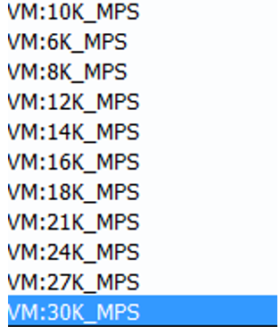
- When finished, click Assign.
- In primary NOAM VIP GUI, restart MP VM.
- From the NOAM GUI, navigate to .
- For each MP server:
- Select the MP server.
- Click Restart.
- Click OK on the confirmation screen.
Wait for the message that tells you that the restart was
successful.
Policy and Charging DRA/DCA Installations: You may continue to see alarms related to ComAgent until you complete PCA/DCA installation.