3 Redundancy, Notifications, Load Balancing, and High Availability
This chapter explains the redundancy, load balancing, and high availability software and hardware components that Oracle Communications Services Gatekeeper provides.
About High Availability
The Services Gatekeeper high-availability feature uses the clustering mechanisms made available by Oracle WebLogic Server. For general information about Oracle WebLogic Server and clustering, see Fusion Middleware Using Clusters for Oracle WebLogic Server at:
http://docs.oracle.com/cd/E15523_01/web.1111/e13709/toc.htm
About Clustering Services Gatekeeper
The default (single-tier) Services Gatekeeper provides a simple, quick method for adding a second clustered system to your implementation to take advantage of the high availability features. Because it is single tier, the installation is much simpler than the multi-tier equivalent. See Services Gatekeeper Getting Started Guide for details on how to set it up.
About Clustering Multi-tier Services Gatekeeper
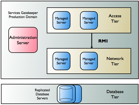
For high availability and security reasons, a multi-tier Services Gatekeeper domain is deployed in two tiers: the Access Tier (AT) and the Network Tier (NT).
The Native SMPP and Native UCP communication services operate entirely in the Network Tier. When two tiers are used, a Server Services provides access to applications in the Network Tier.
Each tier consists of at least one cluster, with at least two server instances per cluster, and all server instances run in active mode, independently of each other. In the context of WebLogic Server, the servers in all clusters are managed servers. Together the clusters comprise a single WebLogic Server administrative domain, controlled through an Administration Server.
There is an additional tier containing the database. Within the cluster, data is made highly available using a cluster-aware storage service, which distributes all state data across all Network Tier instances.
Figure 3-1 shows an example of the deployment of servers in the three tiers.
Figure 3-1 Sample Multi-Tier Production Deployment
Description of ''Figure 3-1 Sample Multi-Tier Production Deployment''
The Access Tier and the Network Tier communicate by using Java remote method invocation (RMI). Application requests are load balanced between the Access Tier and the Network Tier and failover mechanisms are present between the two tiers. See "Managing Traffic Within a Multi-tier Services Gatekeeper" for more information about load balancing and failover in application-initiated and network-triggered traffic flows.
Managing Traffic Within a Multi-tier Services Gatekeeper
This section describes how Services Gatekeeper handles failover in Access Tiers and Network Tiers for both application-initiated and network-triggered traffic.
Failover for Application-Initiated Traffic
Application-initiated traffic consists of all requests that travel from applications through Services Gatekeeper to underlying network nodes.
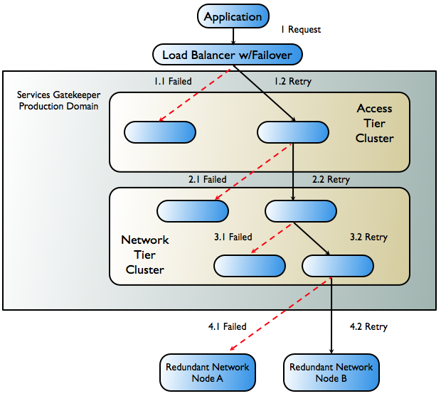
Figure 3-2 shows the worst-case scenario for an application-initiated request as it passes through Services Gatekeeper, and the failover mechanisms that attempt to keep the request active.
Figure 3-2 Failover in Application-Initiated Traffic
Description of ''Figure 3-2 Failover in Application-Initiated Traffic''
The following steps describe the workflow as illustrated in Figure 3-2.
-
The application sends a request to Services Gatekeeper. In a production environment, this request is routed through a hardware load balancer that is usually protocol-aware. If the request towards the initial Access Tier server fails (1.1 in Figure 3-2), either a timeout or a failure is reported. The load-balancer, or the application itself, is responsible for retrying the request.
-
The request is retried on a second server in the cluster (1.2 in Figure 3-2) and it succeeds. That server then attempts to send the request on to the Network Tier.
-
The request either fails to reach the Network Tier or fails during the process of marshalling or unmarshalling the request as it travels to the Network Tier server (2.1 in Figure 3-2).
-
A failover mechanism in the Access Tier successfully sends the request to a different server in the Network Tier cluster (2.2 in Figure 3-2). That server then attempts to send the request on to the network node.
-
The request is sent to a plug-in in the Network Tier that is unavailable (3.1 in Figure 3-2). An interceptor from the interceptor stack retries the remaining eligible plug-ins in the same server and successfully sends the request to an available plug-in (3.2 in Figure 3-2).
-
The attempt to send the request to the telecom network node fails (4.1 in Figure 3-2).
-
The request is forwarded to a redundant network node (4.2 in Figure 3-2). If this request fails, the failure is reported to the application.
Note:
In addition to the mechanisms described above, Services Gatekeeper also enables you to create multiple instances of a single SMPP plug-in type, with multiple binds, which can set up redundant connections to one or more network nodes. This mechanism can also increase throughput and help optimize traffic to SMSCs that have small transport windows.
Failover for Network-triggered Traffic
Network-triggered traffic can consist of the following:
-
Requests that contain a payload, such as terminal location or an SMS message
-
Acknowledgments from the underlying network node that it has processed an application-initiated request. A typical example of this acknowledgment might indicate that an SMS message has reached the SMSC. From an application's perspective, this type of acknowledgment is normally processed as part of a synchronous request, although it may be asynchronous from the network's point of view.
-
Acknowledgments from the underlying network node that the request has been processed by the destination user terminal; for example, an SMS delivery receipt indicating that the SMS message has been delivered. From an application's perspective, this type of acknowledgment is normally handled as an incoming notification.
Services Gatekeeper handles failover for network-triggered traffic by using internal mechanisms in combination with the capabilities of the telecom network node or external components such as load-balancers with failover capabilities.
Some network nodes can handle the registration of multiple callback interfaces. In such cases, Services Gatekeeper registers one primary and one secondary callback interface. If the node cannot send a request to the network plug-in registered as the primary callback interface, the node is responsible for retrying the request by sending it to the plug-in that is registered as the secondary callback interface. This plug-in resides in another Network Tier instance. The plug-ins communicate with each other and ensure both callback interfaces are registered. See "Primary and Secondary Notification" for more information.
For communication services using SMPP, all Services Gatekeeper plug-ins can function equally as receivers of any transmission from the network node.
For HTTP-based protocols, such as MM7, MLP, and PAP, Services Gatekeeper relies on an HTTP load balancer with failover functionality between the telecom network node and Services Gatekeeper. See "Single Notification" for more information.
If a telecom network protocol does not support load balancing and high availability, a single point of failure is unavoidable. In this case, all traffic associated with a specific application is routed through the same Network Tier server and each plug-in has a single connection to one telecom network node.
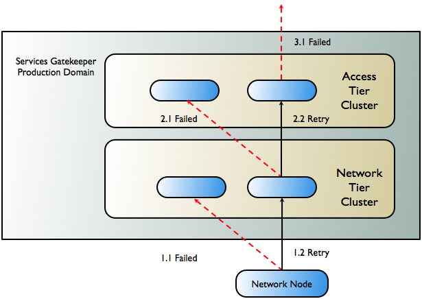
Figure 3-3 shows the worst-case scenario for a network-triggered request for medium life span notifications using a network node that supports primary and secondary callback interfaces.
Figure 3-3 Failover in Network-Triggered Traffic
Description of ''Figure 3-3 Failover in Network-Triggered Traffic''
The following steps describe the workflow as illustrated in Figure 3-3.
-
A telecom network node sends a request to the Services Gatekeeper network plug-in that has been registered as the primary callback interface. It fails (1.1 in Figure 3-3) due to either a communication or server failure.
-
The telecom network node successfully resends the request to the plug-in that is registered as the secondary callback interface (1.2 in Figure 3-3). This plug-in is in a different server instance within the Network Tier cluster.
-
The Network Tier attempts to send the request to the callback mechanism in the Access Tier. The attempt fails (2.1 in Figure 3-3), either because the request fails to reach the Access Tier, or failure occurs during the marshalling or unmarshalling process.
-
The Network Tier resends the request, targeting another server in the Access Tier, and the attempt succeeds (2.2 in Figure 3-3).
Note:
If the failure occurs after processing has begun in the Access Tier, failover does not occur and an error is reported to the network node. -
The callback mechanism in the Access Tier attempts to send the request to the application (3.1 in Figure 3-3). If the application is unreachable or does not respond, the request is considered to have failed and an error is reported to the network node.
Registering Notifications with Network Nodes
Before applications can receive network-triggered traffic (notifications), they must register to do so with Services Gatekeeper, either by sending a request or having the operator set up the notification using management methods. In turn, these notifications must be registered with the underlying network node that will be supplying them. The form of this registration depends on the capabilities of that node.
If registration for notifications is supported by the underlying network node protocol, then the communication service's network plug-in performs the registration, whether the registration is the result of an application-initiated registration request or of an online provisioning step in Services Gatekeeper. All OSA/Parlay Gateway interfaces support such registration for notifications.
Note:
Some network protocols support some, but not all registration types. For example, in MM7 an application can register to receive notifications for delivery reports on messages sent from the application, but not to receive notifications on messages sent to the application from the network. In this case, registration for such notifications can be done off-line when provisioning the MMSC.Whether the notification is set up in the network or by using OAM, Services Gatekeeper correlates all network-triggered traffic with its corresponding application.
Notification Life Span
Notifications are placed into three categories, based on the expected life span of the notification. These categories determine the failover strategies used:
-
Short life span
These notifications have an expected life span of a few seconds. Typically, these are delivery acknowledgments for delivering the request to the network node, where the response to the request is reported asynchronously. For this category, a single plug-in, the originating one, is deemed sufficient to handle the response from the network node.
-
Medium life span
These notifications have an expected life span of minutes up to a few days. Typically, these are acknowledgments for delivering the request to a user terminal. For this category, the delivery notification criteria that have been registered are replicated to one additional instance of the network protocol plug-in. The plug-in that receives the notification registers a secondary notification with the network node, if possible.
-
Long life span
These notifications have an expected life span of more than a few days. Typically, these are registrations for notifications of network-triggered SMS and MMS messages or calls that need to be handled by an application. For this category, the delivery notification criteria are replicated to all instances of the network plug-in. Each plug-in that receives the notification registers an interface with the network node.
Primary and Secondary Notification
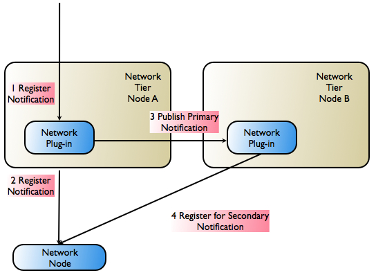
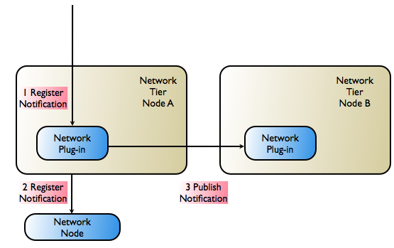
Figure 3-4 illustrates how Services Gatekeeper registers both primary and secondary notifications with network nodes that support them. This capability must be supported by the network protocol in the implementation of the protocol in both the network node and in the communication service's network plug-in.
Note:
The scenario in Figure 3-4 assumes that the network node supports registration for notifications with overlapping criteria (primary/secondary).Figure 3-4 Primary and Secondary Notification Registration
Description of ''Figure 3-4 Primary and Secondary Notification Registration''
The following steps describe the workflow as illustrated in Figure 3-4.
-
The application sends a request to register for notifications to the network protocol plug-in.
-
The primary notification is registered with the telecom network node.
-
The notification information is propagated to another instance of the network protocol plug-in.
-
The secondary notification is registered with the telecom network node.
Note:
Primary and secondary notifications are not necessarily ordered. The most recently registered notification may, for example, be designated as the primary notification.
When a network-triggered request that matches the criteria in a previously registered notification reaches the telecom network node, the node first tries the network plug-in that registered as the primary callback interface. If the network-triggered request fails, the network node has the responsibility of retrying, using the plug-in that registered as the secondary callback interface. The secondary plug-in will have all the necessary information to propagate the request through Services Gatekeeper and on to the correct application.
Single Notification
Figure 3-5 illustrates the registration step in Services Gatekeeper if the underlying network node does not support primary/secondary notification registration.
Note:
The scenario in Figure 3-5 assumes that the network node does not support registration for notifications with overlapping criteria. Only one notification for a given criteria is allowed.Figure 3-5 Single Notification Registration
Description of ''Figure 3-5 Single Notification Registration''
The following steps describe the workflow as illustrated in Figure 3-5.
-
The application sends a request to register for notifications to the network protocol plug-in.
-
The notification request is registered with the telecom network node.
-
The notification information (matching criteria, target URL, and so on) is propagated to another instance of the network protocol plug-in. The plug-in makes the necessary arrangements to be able to receive notifications.
There are two possibilities for high-availability and failover support in this case:
-
All plug-ins can receive notifications from the network node. This is the case with SMPP, in which all plug-ins can function as receivers for any transmission from the network node.
-
A load balancer with failover support is introduced between the network protocol plug-in and the network node. This is the case with HTTP- based protocols. Figure 3-6 illustrates a protocol-aware load balancer failing over traffic to an alternate plug-in.
Note:
Whether or not this failover is possible depends on the network protocol, because the load-balancer must be protocol aware.
Figure 3-6 Failover Performed by Load-Balancer
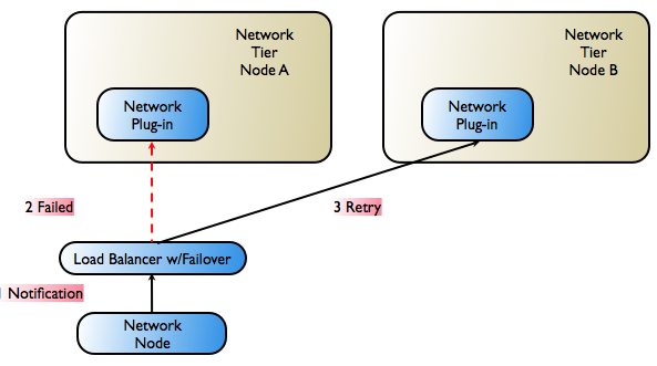
Description of ''Figure 3-6 Failover Performed by Load-Balancer''
Multi-tier Services Gatekeeper Network Configuration
A multi-tier Services Gatekeeper production installation supports redundancy and high availability. A typical installation consists of a number of UNIX or Linux servers connected through duplicated switches. Each server has redundant network cards connected to separate switches. The servers are organized into clusters, with the number of servers in the cluster determined by the needed capacity.
Services Gatekeeper is deployed on an Access Tier, which manages connections to applications, and a Network Tier, which manages connections to the underlying telecom network. For security, the Network Tier is usually connected only to Access Tier servers, the appropriate underlying network nodes, and the WebLogic Server Administration Server, which manages the domain. A third tier hosts the database, which consists of dedicated, redundant servers. For physical storage, you can optionally use a network-attached storage that uses fibre channel controller cards.
Because the different tiers perform different tasks, their servers should be optimized with different physical profiles, including amount of RAM, disk-types, and CPUs. You can scale each tier individually and the number of servers in a tier can be increased without affecting the other tiers.
A sample configuration is shown in Figure 3-7. Smaller systems in which the Access Tier and the Network Tier are located on the same physical servers are possible but only for non-production systems. Particular hardware configurations depend on your specific deployment requirements.
Figure 3-7 Sample Hardware Configuration
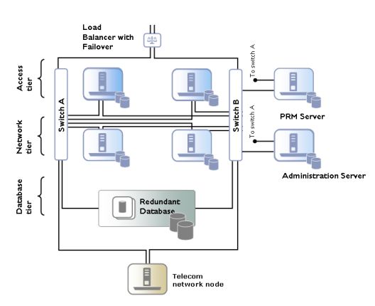
Description of ''Figure 3-7 Sample Hardware Configuration''
In a high-availability configuration, all hardware components are duplicated, eliminating any single point of failure. This means that there are at least two servers executing the same software modules, that each server has two network cards, and that each server has a fault-tolerant disk system, such as RAID.
The Administration Server may have duplicate network cards connected to each switch.
For security reasons, the Access Tier servers can be separated from the Network Tier servers by firewalls. The Access Tier servers reside in a Demilitarized Zone (DMZ) and the Network Tier servers are in a trusted environment.
Geographic Redundancy in Multi-tier Services Gatekeeper
All mulit-tier Services Gatekeeper modules in production systems are deployed in clusters to ensure high availability. This prevents single points of failure in general usage. Within a cluster, the Budget container service regulates the enforcement of SLAs by using a cluster master that enforces bandwidth limits across the cluster, and slaves on each server that synchronize with the master. The Budget service is highly available and is migrated to another server if the cluster master node fails. See Managing and Configuring Budgets in Services Gatekeeper System Administrator's Guide for more information on this mechanism.
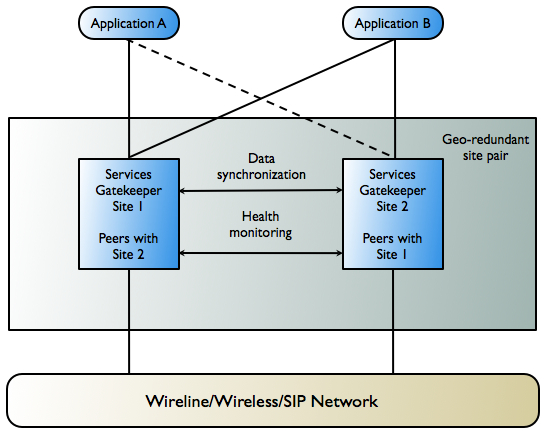
To prevent service failure during catastrophic events, such as natural disasters or massive system outages due to power failures, Services Gatekeeper can also be deployed at two geographically distant sites that are designated as site pairs. Each site, which is a Services Gatekeeper domain, has another site as its peer. Application and service provider configuration information, including related SLAs and budget information, is replicated and enforced across sites.
Note:
Custom, Subscriber, Service Provider Node, and Global Node SLAs cannot be replicated across sites.Figure 3-8 shows an overview of a geographically redundant setup.
Figure 3-8 Overview of Geographically Redundant Site Pairs
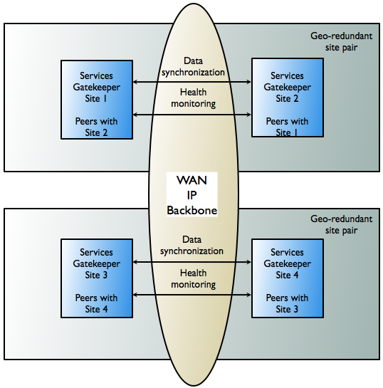
Description of ''Figure 3-8 Overview of Geographically Redundant Site Pairs''
Geographically Redundant Sites
In a geographically redundant setup, all sites have a geographic site name and each site is configured to have a reference to its peer site using that name. The designated set of information is synchronized between these site peers.
One site is defined as the geomaster; the other as the slave. Checks are run periodically between the site pairs to verify data consistency. If mismatches are found, an alarm is triggered, at which point the administrator can force the slave to synchronize to the geomaster by using the syncFromGeoMaster operation from the Administration Console (OCSG -> NT_servername -> Container Services -> GeoStorageService -> Operations -> syncFromGeoMaster), or by using the GeoStorageServiceMBean. Any relevant configuration changes made to either site are written synchronously across the site pairs, so that a failure to write to either the geomaster or the slave causes the write to fail and triggers an alarm.
While the slave is synchronizing with the geomaster, both the geomaster and the slave sites are in read-only mode. No configuration changes can be made. If a slave site becomes unavailable for any reason, the geomaster site becomes read-only either until the slave site is available and has completed all data replication, or until the slave site has been removed from the geomaster site's configuration, terminating geographic redundancy.
If a new site is added to replace the terminated slave site, it must be added as a slave site. The site that is designated the geomaster site must remain the geomaster site for the lifetime of the site configuration.
If a geomaster site fails permanently, the failed site should be removed from the configuration by using the GeoRedundantService container service. If a replacement site is added to the configuration, the remaining operating site must be reconfigured to be the geomaster and the replacement site must be added as the slave.
Applications and Geographic Redundancy
For applications, geographic redundancy means that their traffic can continue to flow if there is a catastrophic failure at an operator site. Even applications that normally use only a single site for their traffic can fail over to a peer site while maintaining ongoing SLA enforcement for their accounts. This scenario is particularly relevant for SLA aspects that have longer term impact, such as quotas.
Figure 3-9 shows an example of geographically redundant site pairs and applications.
Figure 3-9 Geographically Redundant Site Pairs and Applications
Description of ''Figure 3-9 Geographically Redundant Site Pairs and Applications''
In many respects, the geographic redundancy is not transparent to applications. There is no single sign-on mechanism across sites, and an application must establish a session with each site it intends to use. In case of site failure, an application must manually fail over to a different site.
Application and service provider budget and configuration information are maintained across sites, but state for ongoing conversations is not maintained across sites. Conversations in this context are defined in terms of the correlation identifiers that are returned to the applications by Services Gatekeeper or are passed to Services Gatekeeper from the applications. Any state associated with a correlation identifier exists on only a single geographic site and is lost if a site-wide failure occurs. Conversational state includes, but is not limited to, call state and registration for network-triggered notifications. Conversational state is considered volatile, or transient, and is not replicated at the site level.
This means that conversations must be conducted and completed at their site of origin. If an application must maintain conversational state across sites, for example, to maintain a registration for network-triggered traffic, it must register with each site individually. This type of affinity does allow load balancing between sites for different or new conversations. For example, because each request to send an SMS message constitutes a new conversation, sending SMS messages can be balanced between the sites.
The following is a high-level outline of the redundancy functionality:
-
The contractual usage relationships represented by SLAs can be enforced across geographic site domains. The enforcement covers service provider group and application group SLAs.
-
Service provider and application account configuration data, including any changes to this data, can be replicated across sites. This reduces the administrative overhead of setting up geographically redundant site pairs.
-
Alarms are generated when:
-
Peer sites fail to establish a connection with each other for a configurable number of times.
-
There is a configuration mismatch between the two sites; for example, if site A treats site B as a peer, but site B does not recognize site A as a peer
-
The paired sites do not have identical application and service provider configuration information, including related SLAs and budget information
-
The master site fails to complete a configuration update to the slave site
-