5 Core Functionality
This chapter describes Oracle Communications Design Studio and Oracle Communications Unified Inventory Management (UIM) core functionality. This functionality supplies the infrastructure that you use to manage your inventory.
Much of the core functionality is provided by the UIM common patterns and the entities that enable them. Search functionality is provided by the application framework. See "Core Platform" for more information.
This chapter includes information about the following functionality:
Lifecycle management is also provided by the core platform, but is covered in a separate chapter. See "Life Cycles and Statuses" for more information.
Searching
UIM provides a search framework that enables you to find entities based on a wide variety of criteria that depend on the entity type. You can combine criteria for an even more specific search. For example, you could search for all Equipment entities that are based on a particular specification and are in the Pending Install inventory status.By default, you can search for the data elements that are common to all entities of the same type. You can also add additional search criteria corresponding to the characteristics that have been defined in specifications of the same type. By adding additional fields to the search criteria, you can also search for entities based on characteristics that have been defined in specifications of a particular entity type.
For example, if one Place specification includes a characteristic called Elevation and another includes a characteristic called Sales Area, you can include one or both of those characteristics in a search for Place entities.
For some entity types, you can search by relationships. For example, you can search for equipment based on relationships to physical devices, logical devices, and places. You can search for pipes based on relationships to terminating points, networks, and logical devices. You can also search for inventory groups based on relationships to places.
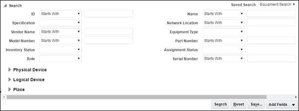
Figure 5-1 shows the Search page for Equipment entities, which enables you to search on standard equipment data elements.
You can save search criteria that you use frequently. For example, if you often search for Equipment entities of a particular model number and vendor, you can save those criteria for reuse. You can designate a saved search as the default search for an entity type. The default search criteria appear automatically when you open the Search page for that entity type.
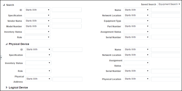
You can also expand the Search section to search for equipment based on associations to a physical device, logical device, or place. Figure 5-2 shows the Physical Device section expanded.
When the results of a search are displayed, you can select entities and perform actions on them. The actions you can take depend on entity type. For a Logical Device search, for example, you can edit, duplicate, or delete from the Search Results section. Figure 5-3 shows results from a search for Logical Device entities.
Searching for Pending Resources
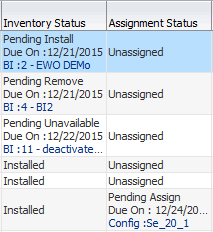
Search results for resources in pending Inventory or Assignment statuses include information about the date when the pending status will be resolved. These search results also include information about the source of the pending status (business interactions and engineering work orders for Inventory status; configurations and connectivity design versions for Assignment statuses.) You use this information to determine whether you can assign or reference a resource. See "About Assigning Pending Resources" for more information.
Figure 5-4 illustrates the display of this information in search results.
Figure 5-4 Lifecycle Information in Search Results
Description of "Figure 5-4 Lifecycle Information in Search Results"
Searching by Using Web Services
You can include searches when you interact with UIM by using web services. Custom web service operations can include calls to the search methods provided by the Finder class. See UIM Web Services Developer's Guide for information about creating and deploying custom web services.
Configurations
Some entity types can optionally be associated with configurations. A configuration is a versionable collection of facts about an entity, such as the design details of a service or the hardware resources associated with a logical device.
For entities that have configurations, basic information that is likely to stay the same over time, such as the name and description, are stored as part of the entity itself. Information that can change over time, such as the specific hardware that makes up a logical device or the resources required to fulfill a service, are stored in the entity configuration. For example, a customer might maintain a DSL service for a long period, but the router used for that service could change over time, as could the phone numbers and associated email accounts.
Configurations can be versioned, enabling you to maintain a history of how the entity has evolved over time. You can access previous versions in read-only form.
The following entity types can have configurations:
-
Flow interfaces
-
Logical devices
-
Logical device accounts
-
Networks
-
Pipes
-
Places (of type Site only)
-
Services
Connectivity entities do not have configurations, but they do have design versions, which are similar. See "About Design Versions" for more information.
Configurations include configuration items, which you use the specify the details of the configuration. For example, you use configuration items to specify the resources that enable a service. You can associate resources to configuration items in two ways:
-
Assignment. When you assign a resource to a configuration item, that resource is consumed. For example, in a consumer VoIP service, you can assign a handset to the service configuration. In most cases, the resource can be consumed only once, so allocation places it in Assigned state. See "Consumption" for more information about consumption.
-
Reference. When you reference an entity from a configuration, you indicate that the configuration has an interest or dependency in the entity but does not consume it. For example, a cable subscription service requires a cable controller but does not consume it. In this case, a configuration item would reference the controller rather than assigning it. See "Understanding Entity References" for more information about entity references.
Configuration items can also include characteristics that enable you to capture specific details. To organize configuration items and put them in context, you can arrange them in a hierarchy.
As the configuration of an entity changes, you create successive configuration versions that describe its composition at various times. Only one version can be in service at a time.
Some services can have multiple pending configurations where more than one configuration is in progress at a time. See "About Multiple Pending Configurations" for information on this functionality.
Understanding Configuration Specifications
Like other entities, configurations are defined by specifications. You define configuration specifications and relate them to entity specifications in Design Studio. Each configuration-enabled entity type has a corresponding configuration type. For example, you can associate a Logical Device Configuration specification only to a Logical Device specification.
You can associate a configuration specification with multiple entity specifications of the same type. You can also associate a single entity specification with multiple configuration specifications. For example, you can associate multiple Logical Device specifications with a single Logical Device Configuration specification and you can associate a single Logical Device specification with multiple Logical Device Configuration specifications.
When you define a configuration specification, you define its configuration items. The specification defines how configuration items are organized, whether they are required, the minimum and maximum number of resources that can be assigned or referenced in the item, and any characteristics associated with them. See the Design Studio Help for more information about defining configuration items.
Configuration Example
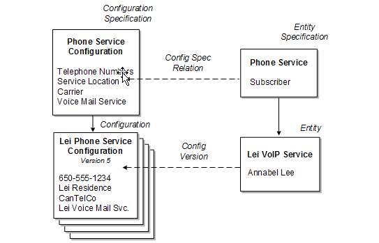
Figure 5-5 illustrates the relationships among entity specifications, configuration specifications, entities, and configuration versions. A Service specification for a telephony service is associated to a Service Configuration specification. The service itself stores only the subscriber name. The configuration stores the service location, carrier, one or more telephone numbers, and so on.
Initially, a Service entity based on the entity specification is created in UIM. Then successive configuration versions based on the configuration specification store the relevant information as it changes over time.
Figure 5-5 Specifications, Entities, and Configuration Versions
Description of "Figure 5-5 Specifications, Entities, and Configuration Versions"
Maintaining Configurations in UIM
When an entity in UIM is associated with a configuration specification, you can create configuration versions for that entity. The configuration versions are based on the configuration specification associated with the entity specification. (If an entity specification is associated with multiple configuration specifications, you select which configuration specification to use.)
Configuration versions have a life cycle so that you can develop a new configuration version while a previous one is still valid. See "Configuration Life Cycles and Statuses" for more information. When you create a new configuration version, the values of the old one are copied. You modify and add to these values as necessary. When you complete a configuration version, it becomes active, replacing the previous one.
For example, if you are replacing the handset in a VoIP service, you create a new configuration version that includes the new device. When the handset is activated, the new configuration version is complete, replacing the previous version.
About Multiple Pending Configurations
UIM supports multiple pending configurations, which means that more than one configuration may be in progress at a given time. Multiple pending configuration functionality is only available for non-network services. You determine if a service is a network service by the Network Oriented Service Type attribute setting on the service entity. For network services, only one configuration can be in progress at a time.
The multiple pending configuration functionality is enabled by the uim.mpcenabled system property in the system-config.properties file. The default is for the functionality to be enabled. See UIM System Administrator's Guide for information on this property. You can also create multiple pending configurations for a service using the Service Fulfillment Web Service. See UIM Web Services Developer's Guide for more information.
You can create an in-progress configuration before or after any existing in-progress configuration when:
-
The multiple pending functionality is enabled in the system-config.properties file.
-
Each configuration version is associated to its own Business Interaction.
The effective date on the Business Interaction determines the start date value for the configuration. You can create configurations before or after a configuration that is in progress, however the start date must always be on or after the current date.
Each pending configuration version must have a different start date; no two pending configuration versions can have the same start date.
Adding and Removing Resources
With multiple pending configuration functionality, you can add and remove resources across multiple configuration versions that are in progress. Any resource-related changes, such as adding or removing resources, that you make in the current pending configuration version is cascaded into the future-dated pending configuration versions.
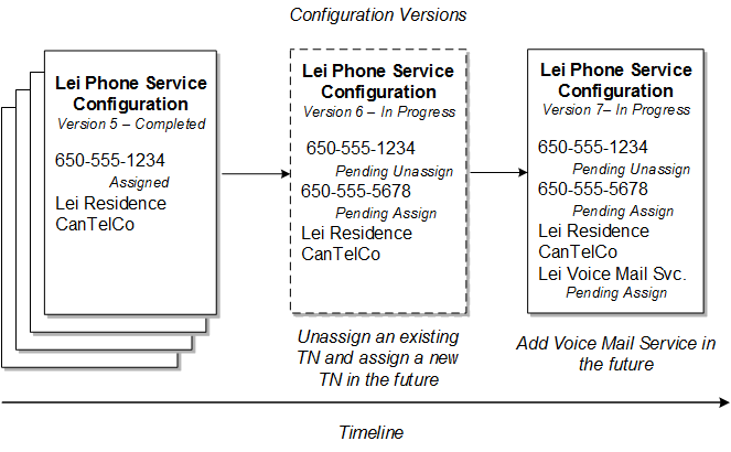
For example, from our previous configuration example in Figure 5-5, you can create a new configuration version and add a new telephone number in a future-dated configuration. You can also remove a telephone number in a future-dated configuration which is further in the future than the addition. This results in two configuration versions being in progress.
Figure 5-6 shows how the resource statuses change as changes are made in the future-dated configurations. In this example, version 5 is the latest configuration in Completed status, and you create version 6 with a new telephone number (650-555-5678) added to the Lei Phone Service. In version 6, you also unassign the existing telephone number from the Lei Phone Service. Then, you create another configuration, version 7, with a date later than version 6, and add a voice mail service. The result is two configuration versions that are in progress. For the telephone number configuration items, there is now one Pending Assign telephone number, and one Pending Unassign telephone number.
Figure 5-6 Adding and Removing Resources in Future Configurations
Description of "Figure 5-6 Adding and Removing Resources in Future Configurations"
Inserting a Configuration Version Between Two Others
If you create a configuration with a start date in between two in-progress configurations, UIM reorders the configuration versions. Any resource-related changes, such as adding or removing resources, that you make in the newly inserted configuration is cascaded into the future-dated pending configurations.
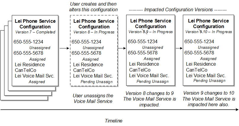
For example, for the Lei Phone Service, if you remove or unassign the voice mail service in a new configuration that is before the start date of version 8, and after version 7, the result is an inserted configuration and a reordering of the later versions.
The later versions are also impacted by having the voice mail service change to a Pending Unassign status for the resource on those configuration items.
Figure 5-7 shows the resulting configuration version changes. The inserted configuration version is shown in the dashed box as the new version 8. The existing version 8 configuration changes to version 9, and similarly, the existing version 9 changes to version 10. The configuration version numbers are in order of their respective start dates.
Each configuration version is associated to a Business Interaction and each Business Interaction effective date determines the configuration version start date.
Figure 5-7 Inserting a Configuration and the Impacted Configuration Versions
Description of "Figure 5-7 Inserting a Configuration and the Impacted Configuration Versions"
Changing the Start Date of a Configuration Version
If you change the effective date on the Business Interaction, it also changes the start date of the associated configuration version. Changing this date can affect the order of the configuration versions.
Note:
You can only change the start date on a configuration version when it is not associated to a Business Interaction. If the configuration version is associated to a Business Interaction, then the date can only be modified on the associated Business Interaction itself.
Changing the Start Date to an Earlier Date
If more than one configuration is in progress, you must consider the following points before changing the start date of a configuration version to an earlier date:
-
You cannot move a changed or updated configuration item before a configuration version that created or added the assignment or reference.
-
You cannot move a configuration item having a second assignment or reference before a configuration version that has updated the first assignment or reference.
-
You can move a configuration item having a pending assignment before a configuration version that has the same resource assignment; however, if you do so, the existing resource assignment will be automatically removed.
Note:
Ensure configuration version start date changes are the same for referencing and de-referencing items as the changes for assignments.
Changing the Start Date to a Later Date
If more than one configuration is in progress, you must consider the following points before changing the start date of a configuration version to a later date:
-
You cannot move a changed or updated configuration item if there is any update on the assignment in between two in-progress configuration versions.
-
You cannot move a configuration item having a second assignment or reference after a configuration version that has updated this assignment or reference in between two in-progress configurations.
-
You cannot move a configuration item that has been changed or updated and that has a pending assignment or pending reference, after a configuration version that has added a second assignment.
Note:
Ensure configuration version start date changes are the same for referencing and de-referencing items as the changes for assignments.
Completing a Configuration
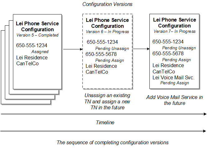
With multiple pending configuration functionality, you can complete configuration versions that are in progress. If a Service entity contains multiple pending configuration versions, you must first complete the initial version of the pending configuration before completing the immediate succeeding version. For example, if a service configuration contains five configuration versions, you must first complete configuration version 1, and then complete configuration version 2, and so on. For example, in Figure 5-8, you must first complete configuration version 6, and then complete configuration version 7, and so on.
Figure 5-8 Sequence of Completing Configuration Versions
Description of "Figure 5-8 Sequence of Completing Configuration Versions"
Canceling a Configuration
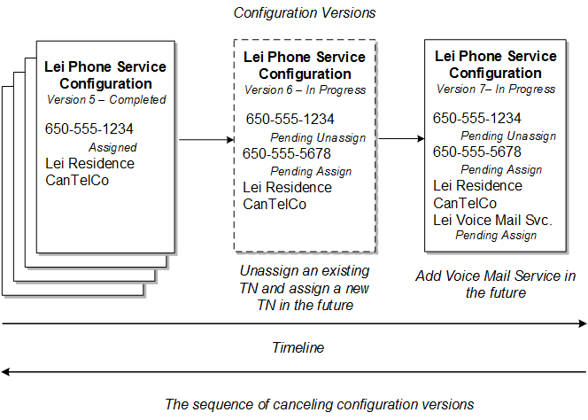
With multiple pending configuration functionality, you can cancel configuration versions that are in progress. If a Service entity contains multiple pending configuration versions, you must first cancel the latest version of the pending configuration before canceling the immediate preceding version. For example, in Figure 5-9, you must first cancel configuration version 7, and then cancel configuration version 6, and so on.
Figure 5-9 Sequence of Canceling Configuration Versions
Description of "Figure 5-9 Sequence of Canceling Configuration Versions"
Disconnecting a Service with Multiple Pending Configurations
With multiple pending configuration functionality, you can disconnect a service in In Service status having multiple pending configurations, with each pending configuration version associated to a different Business Interaction.
When you disconnect a service in In Service status having multiple pending configurations, a new disconnect configuration version is created after the latest pending configuration version, and the service status transitions from In Service to Pending Disconnect. The default for the start date of the disconnect configuration version is the date of the latest pending configuration version plus one calendar day.
You must create a new business interaction and associate it with the disconnect configuration version to perform actions on the disconnect configuration version. You can create an in-progress configuration version for the service that is in Pending Disconnect status, provided that the effective date of the in-progress configuration version you are creating is less than that of the disconnect configuration version.
If a service having multiple in-progress configuration versions is in Pending status, you can still disconnect the service, in which case the service status transitions from Pending to Pending Disconnect.
Capacity
In UIM, capacity refers to the amount and type of something that entities require or provide. UIM provides a capacity framework that enables you to define, measure, and track the usage of capacity.
UIM pipe and signal termination points entities use the capacity framework to manage bandwidth. Bandwidth specifies the speed and amount of data that can be transferred from one place to another. See "Pipes" for more information about bandwidth.
You use measurement types, units of measure, and capacity types to define capacity and how it is measured. See "Defining and Measuring Capacity" for more information. You associate Capacity Provided and Capacity Required specifications with other entity specifications to define how they use capacity. See "Configuring Capacity" for more information.
Table 5-1 list the entities that work together to manage capacity in your network, along with examples of how they are used for bandwidth.
Table 5-1 Capacity Entities and Specification
| Entity | Definition | Bandwidth Example |
|---|---|---|
|
Measurement Type |
Classifies how capacity is measured. |
Bit rate |
|
Unit of Measure |
Quantifies how capacity is measured. |
Bits per Second (bps), Kilobits per Second (kbps), Megabits Per Second (Mbps), Gigabits per Second (Gbps) |
|
Capacity Type |
Defines the kind of capacity that an entity provides or consumes. |
Bandwidth |
|
Capacity Provided |
Defines the capacity an entity offers in terms of a total amount and a consumable percentage. The percentage must equal 100% for channelized pipes but can be less than or greater than 100% for packet-switched pipes. |
44.736 Mbps at 100% 44.736 Mbps at 200% |
|
Capacity Required |
Defines the capacity an entity consumes in terms of an amount required and a unit of quantity of the required amount. |
1.544 Mbps |
An additional type of capacity-related entity, the signal termination point, is available for use with pipes. Signal termination points enable you to define channelized signal structures that help define capacity for TDM (time-duplex multiplexing) connectivity. See "Configuring Pipe Capacity" for more information.
Defining and Measuring Capacity
You define capacity by designing measurement types, units of measure, and capacity types in Design Studio. These artifacts reference each other to form a capacity definition that you can use with other entities.
The Base Measurements cartridge includes predefined artifacts related to bandwidth. The cartridge includes a bit rate measurement type, a set of related units of measure including bps, kbps, Mbps, Gbps, and a bandwidth capacity type. Along with other base cartridges, the Base Measurements cartridge is delivered in the core UIM package. You can find it in the following location when UIM is installed:
UIM_Home/cartridges/base/
See UIM Cartridge Guide for more information.
Configuring Measurement Type
Measurement types classify related groups of units of measure. For example, the measurement type bit rate classifies units of measure such as bits per second (bps), kilobits per second (kbps), and so on. See the Design Studio Help for detailed instructions about creating measurement types.
Configuring Units of Measure
Units of measure define the units used to measure capacity in UIM. A unit of measure is a quantity or increment by which something is divided, counted, or described. For example, kbps is a unit that measures a bit rate. Related units of measure are grouped into measurement types.
When you define a unit of measure in Design Studio, you configure the following data elements:
-
Display Unit Value: The text that is displayed in menus and lists for this unit of measure.
-
Type of Measurement: The measurement type to which this unit of measure belongs. You specify this property by selecting or creating a measurement type.
-
Default: Determines whether this unit of measure appears as the default value for its measurement type in menus and lists. Only one unit of measure can be the default for each measurement type.
-
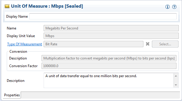
Conversion Factor: A multiplier used to convert this unit of measure to another unit of measure. For example, for an Mbps unit of measure, you could enter 1000000 as the conversion factor to bps.
The conversion factor is used internally by the UIM capacity framework so that it can determine how much capacity is available, required, and consumed, even when different units of measure are involved. For example, different pipe entities could express their capacity provided or required in kbps and Mbps. Using conversion factors, the capacity framework can convert their capacities to a common unit of measure (bps) to determine whether requirements can be met.
Table 5-2 shows some standard conversions for bit rates.
Table 5-2 Sample Conversion
| Unit | Conversion Factor |
|---|---|
|
bps |
1 |
|
kbps |
1000 |
|
Mbps |
1,000,000 |
Figure 5-10 shows the Properties tab for the Mbps unit of measure with the conversion factor.
Configuring Capacity Type
A capacity type defines a kind of capacity that an entity provides or consumes. The bandwidth capacity type is provided in the Base Measurements cartridge. You associate a measurement type to a capacity type to specify how the capacity is measured.
See the Design Studio Help for detailed information about creating and configuring capacity types.
Configuring Capacity
You define Capacity Provided and Capacity Required specifications to define the capacity that entities offer and require. When you associate a Capacity Provided specification with another entity specification, the capacity defined in the Capacity Provided specification is offered by entities that you create in UIM based on that specification. Similarly, when you associate a Capacity Required specification with an entity specification, the capacity defined in the Capacity Required specification becomes an enablement requirement for entities based on the specification.
Note:
You cannot associate Capacity Provided specifications with Pipe entities that are associated with signal structures. These pipes derive their capacity provided from their signal structures. See "Understanding Capacity and Signal Structure" for more information.
Configuring Capacity Provided
Capacity Provided specifications define the capacity that entities offer. When you configure a Capacity Provided specification, you use the following data elements:
-
Capacity Type: Determines the type of capacity offered.
-
Total Amount: The amount of the capacity type that an entity can provide.
-
Unit of Measure: The units by which the total amount is measured, defined by a unit of measure.
-
Consumable Percentage: The percentage of the total amount that can be consumed. A consumable percentage over 100% indicates that the capacity can be oversubscribed.
For example, bandwidth is a capacity type that is measured by bit rate. Bit rates are measured in units such as bps or Mbps. Entities such as pipes provide and consume bandwidth at a bit rate that you specify. An OC3 bandwidth pipe can provide 155.52 Mbps, for example, and packet pipes can consume varying rates of that capacity.
Figure 5-11 shows an example of how the entities are set up for packet type pipes that are not channelized.
For example, you can define an OC3 Pipe using the Capacity Provided entity that provides bandwidth of 155.52 Mbps, 100% of which can be consumed. Pipes that can use that capacity are associated with capacity-required entities.
Note:
Pipes and signal termination points are the only entities that can offer capacity by default.
In UIM, when you create an entity based on a specification that includes a relation to a Capacity Provided specification, the provided capacity is automatically associated to the entity. An entity can offer multiple types of capacity, so it can have relationships to multiple capacity-provided entities. An entity specification can be related to only one Capacity Provided specification of a given capacity type, however.
For example, a Pipe specification can be related to only one Capacity Provided specification for the Bandwidth capacity type. If you create another type of capacity that applies to a pipe, the Pipe specification can also be related to one Capacity Provided specification of the new capacity type.
Configuring Capacity Required
A Capacity Required specification defines the capacity that an entity requires. When you configure capacity required, you use the following data elements:
-
Capacity Type: Determines the type of capacity required.
-
Required Amount: The amount of the capacity type that an entity requires.
-
Unit of Measure: The units by which the total amount is measured, defined by selecting a unit of measure.
-
Quantity: The number of units of the required amount value that an entity requires for a given capacity type. For example, when defining capacity required for a pipe that is enabled by a facility pipe that supports TDM technology at any point in its path, you must set the quantity equal to the number of channels required. Specifying the quantity in this way enables you to use the path analysis functionality provided by UIM to locate facility pipes for service trails. See "Enabling Pipes Automatically with Path Analysis" for more information.
For non-TDM technologies, the quantity can be set to 1. Path analysis calculates the total bandwidth required and finds available packet facilities in addition to finding available TDM facilities to support the end-to-end enablement of the pipe.
You associate Capacity Required specifications to specifications of entities that require capacity. For example, you can associate a DS1 Capacity Required specification to a DS1 Pipe specification.
In UIM, when you create an entity based on a specification that is related to a Capacity Required specification, the capacity required is automatically created and related to the entity.
An entity can require multiple types of capacity, so its specification can have relationships to multiple Capacity Required specifications; however, an entity specification can be related to only one Capacity Required specification of a given capacity type. For example, a Pipe specification can be related to only one Capacity Required specification for the Bandwidth capacity type.
Consumption
Entities in your inventory are used by other entities in various ways. For example, a handset can be assigned to a VoIP service or a telephone number can be reserved for use by a customer starting next week.
In UIM, the consumption framework is the mechanism by which you manage how entities use each other. There are several forms of consumption, including assignment, reservation, and conditions. See "Resource Reservations" and "Conditions" for more information. Entity reference is similar to assignment, but does not involve actual consumption. See "Understanding Entity References" for more information.
Assignment
The most common way the entities consume each other is by assignment. When an one entity is assigned to another, the first entity is consumed by the second. For example, consumption occurs when:
-
A physical port is assigned to a pipe termination point
-
A device interface is assigned to a logical device
-
An equipment entity is assigned to a service
In many cases, assignment, and therefore consumption, takes place in entity configurations. For example, an IP address in the form of a Custom Network Address entity can be assigned as a configuration item in a logical device configuration.
Table 5-3 lists the entities that can consume entities and the entities that can be consumed.
Table 5-3 Consumers and Consumable Entities
| Consumer Entity | Consumable Entity |
|---|---|
|
Place Note: Only Site-type Place entities can have configurations. |
Custom network address Custom object Device interface Place (address, address range, location, site) Logical device Physical device Service |
|
Logical device |
Custom network address Custom object Device interface |
|
Network |
Custom network address Custom object Logical device |
|
Pipe |
Pipe |
|
Pipe termination point |
Custom network address Custom object Device interface Equipment Logical device Network Physical connector or port Physical device |
|
Service |
Custom network address Custom object Device interface Equipment Equipment holder Place (location or site) Logical device Logical device account Media stream Network Physical connector or port Physical device Pipe Service Telephone number |
About Shared Consumption of Entities
Entities can be consumed by one entity or by more than one entity. For example, in a normal POTS service, the service consumes a single telephone number. The service has only one number and the number can be assigned to only one service. But in a party-line telephone environment, the same number is shared between two or more services. Each service has only one number, but the same number is shared among several services.
You configure consumption rules in Design Studio when you define specifications. You can designate that a consumable entity can be consumed by one or more consuming entities. You can also designate that a consuming entity can consume one or more consuming entities.
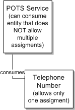
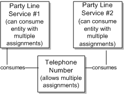
Figure 5-12 shows an example based on POTS service. A POTS service can consume a telephone number and the telephone number can be consumed by only one POTS service. In this case, the Telephone Number specification is configured so that it cannot be assigned to multiple entities. The Service specification is configured so that it cannot assign entities that allow multiple assignments. This ensures that the telephone number cannot be assigned to multiple services and that the service cannot consume a telephone number that can be assigned to multiple services.
Figure 5-13 shows a party line service. A party line service allows customers to share one telephone number, preventing them from making calls at the same time. In this case, the Telephone Number specification is configured to allow assignment to multiple entities. The party line service is configured so that it can consume entities that allow multiple assignments.
About Assigning Pending Resources
Resources can be in pending lifecycle statuses that affect the way you consume them. Pending statuses include both Inventory statuses, such as Pending Install and Assignment statuses, such as Pending Unassign. For definitions of life cycle statuses and information about when they occur, see "Life Cycles and Statuses".
Pending statuses occur in two situations:
-
When the resource is created, assigned, or unassigned in a business interaction context. Resources in these scenarios remain in a pending status until you complete the business interaction.
-
When the resource is assigned or unassigned as part of a configuration version or connectivity design version. Resources that you assign in a configuration version or connectivity design version remain in a pending status until you complete the version.
For example, when you create a resource in the context of a business interaction, the resource is in Pending Install status until you complete the business interaction. Similarly, when you assign a resource in the context of a business interaction or in a configuration version that has not been completed, the resource's assignment status is Pending Assign.
UIM enables you to consume resources in pending statuses under certain conditions. You can assign a resource in a pending status as long as its effective date (the date on which the pending status will be resolved) is before the effective date of the configuration or other entity to which it is assigned.
You can consume resources in the following statuses:
Table 5-4 Consumable Pending Statuses
| Status | Status Type |
|---|---|
|
Pending Install |
Inventory |
|
Pending Available |
Inventory |
|
Pending Unassign |
Assignment |
Consumption of pending resources creates dependencies based on effective dates. UIM manages these dependencies by preventing consumption when it is not allowed. If you create a resource in the context of a business interaction, UIM prevents you from assigning that resource to a consumer in another context or in current inventory until the business interaction is complete.
UIM also manages dependencies within business interactions. A business interaction can include both the creation of a resource and its assignment to a consumer. For example, suppose you use an engineering work order to create a logical device that represents a provider-edge router. You want to assign the logical device to a connectivity design version that you are completing in the same engineering work order. The effective dates of the logical device and connectivity design version are the same, but UIM allows the assignment. When completing the engineering work order, UIM ensures that the logical device status changes to Installed before the assignment occurs.
The same dependency management occurs for other statuses. For example, if a resource is unassigned from one consumer and assigned to another in the same business interaction, UIM ensures that the status changes occur in the proper order to allow the assignment.
Consumption of pending resources means that they can have two separate pending statuses. For example, a device interface could be in Pending Unassign status for one business interaction and in Pending Assign status for another business interaction. To avoid circular dependencies, UIM prevents any resource from having more than two pending statuses at the same time.
You search for and assign pending resources the same way you do other resources. Search results for pending resources include information about their statuses and effective dates so you can determine whether you can assign them. See "Searching for Pending Resources" for more information.
Example of Assigning Pending Install Resources
This example illustrates the assignment of pending resources to a service configuration.
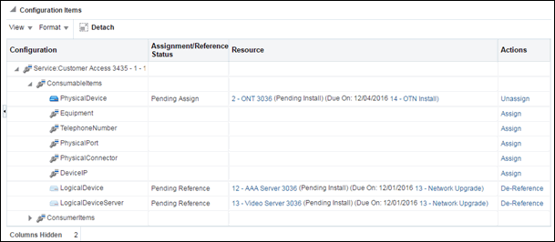
It is November 20th and you are working on setting up a customer access service configuration with a start date of December 15th. The service configuration requires the reference a AAA server logical device and a video server logical device. The configuration also requires the assignment of an Optical Network Terminal (ONT) physical device.
None of these resources are currently available, but a AAA server and video server are being installed as part of an engineering work order with a effective date of December 1st and the ONT is being installed as part of an engineering work order with a effective date of December 4th.
Because the effective date of the service configuration (December 15th) is after those of the resources (December 1st and December 4th), you can assign the resources to the configuration.
Figure 5-14 illustrates this scenario. Note that the Assignment status of the resources is either Pending Assign or Pending Reference. The Resource column shows the Inventory status (Pending Install) of each resource. It also shows the due dates of the resources and information about engineering work orders to which they belong. (Two columns are hidden so the information is visible in the figure.)
Figure 5-14 Consumption of Pending Resource in Service Configuration
Description of "Figure 5-14 Consumption of Pending Resource in Service Configuration"
The Inventory statuses will change of the resources will changed to Installed on December 1st and December 4th, when you complete the engineering work orders. The Assignment statuses will change to Assigned and Referenced on December 15th, when you complete the service configuration.
Example of Assigning Pending Unassign Resources
You can search for, assign, and reference Pending Unassign resources in the same way as Pending Install resources. For example, you may need to terminate a connectivity on a device interface on which there are no currently unassigned device interfaces. You can search for and assign a device interface that is in Pending Unassign status, as long as the effective date of the connectivity version is later than the date on which the device interface will transition to Unassigned status.
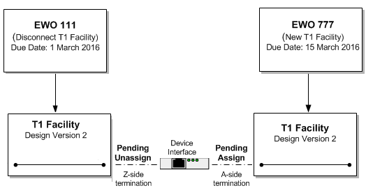
Figure 5-15 illustrates such a scenario. In this case, you require a device interface to terminate the A side of a new T1 facility that you are creating as part of EWO 777. No currently unassigned device interfaces exist, but your search finds a suitable device interface that is in Pending Unassign status as part of EWO 111. That EWO has a effective date of 1 March 2016, which is before the 15 March 2016 effective date of EWO 777. You can therefore terminate the new T1 connectivity with this device interface.
On 1 March 2016 the device interface will transition automatically from Pending Unassign to Pending Assign status. On 15 March, when you complete EWO 777, the device interface will transition to Assigned status.
Figure 5-15 Assignment of Pending Unassign Resources
Description of "Figure 5-15 Assignment of Pending Unassign Resources"
Understanding Entity References
You use entity references to represent an interest or dependency between a configuration and an entity. An entity reference is similar to an assignment, except that the referenced entity is not consumed by the configuration.
For example, a mobile GSM service is provisioned on a Home Location Register (HLR) device. The relationship between the GSM service and the HLR device provides important information about how the service is realized on the network, but the device is not consumed by the service. Similarly, a cable TV subscription service requires a cable controller (modeled as a logical device in UIM), but the service does not consume the device.
Because referenced entities are not actually consumed, they are not affected by the Blocked condition. A resource that has a Blocked condition cannot be consumed (assigned), but it can be referenced.
You define an entity reference in Design Studio when you define a configuration item. Just as with defining a configuration item for assigning resources, you can limit the valid options to particular specification types or to entities based particular specifications. See the Design Studio Help and the UIM Help for more information.
Table 5-5 lists the configurations that can include entity references and the types of entities that can be referenced. Pipe configurations are not included in the table because they cannot include entity references.
Table 5-5 Configurations and Referenceable Entities
| Configuration | Referenceable Entity |
|---|---|
|
Logical Device Network Place (site only) Service |
Business Interaction Custom Network Address Custom Object Device Interface Equipment Inventory Group Logical Device Logical Device Account Network Party Physical Connector Physical Device Place Pipe Physical Port Product Service Telephone Number |
Resource Reservations
In UIM, you can reserve resources to prevent them from being used by other entities or processes. You can reserve resources if they are unassigned, not already reserved, and do not have a condition code that prevents assignments.
You can reserve resources for a particular project, user, or service specification. Reservations can be designated as long-term (30 days by default) or short-term (10 minutes by default). If the reservation is not redeemed by the expiry date, the resource is released back into inventory. See UIM Developer's Guide for more information about defining reservation periods.
In UIM, you redeem a reserved resource when you assign the resource to a configuration item using a service, logical device, network, or site configuration. By default, UIM does not validate the redemption to ensure that it matches the reservation. You can optionally associate a ruleset to the reservation to ensure that reservation validation occurs. See UIM Developer's Guide for information about the RESERVATION_CHECK_REDEEMER ruleset.
You can reserve resources from an entity's Summary page, or you can use the Reservation link in the UIM navigation section to reserve multiple resource items on one reservation.
The following resources can be reserved:
-
Custom network addresses
-
Custom objects
-
Device interfaces
-
Equipment
-
Equipment holders
-
Flow identifiers
-
Logical devices
-
Logical device accounts
-
Media streams
-
Networks
-
Physical connectors
-
Physical devices
-
Physical ports
-
Services
-
Telephone numbers
See the UIM Help for more information about reserving and redeeming resources.
Conditions
Conditions are a way to limit the availability of an entity for a period. A condition therefore behaves as a consumer of the entity, similar to an assignment. Table 5-6 lists the types of conditions.
Table 5-6 Condition Types
| Condition Type | Definition |
|---|---|
|
Blocked |
This condition is used for resources that cannot be consumed because of some administrative reason. This condition prevents users from making assignments to this resource. Blocked resources cannot be consumed, but they can be referenced. See "Understanding Entity References" for more information about references. |
|
Informational |
This condition does not affect the availability of a resource, but it provides additional information about the resource. |
|
Warning |
This condition supplies additional information about a resource. A warning condition does not affect the availability of a resource but warns the user that there may be reasons not to use it. |
See the UIM Help for more information about applying conditions.
Involvements
Many entities in UIM are involved with each other because of the way the inventory is modeled. For example, a service configuration can include configuration items for one or more places or resources, and a logical device can provide one or more device interfaces. These kinds of relationships are explicitly defined in the UIM model and the application provides tools to manage them.
UIM also enables you to define custom involvements between entities that are not otherwise associated. You can define Custom Involvement specifications in Design Studio to define various kinds of associations in your inventory. For example, you could define Custom Involvement specifications that define involvements between physical connectors and the ports they support.
UIM provides a default specification for a special kind of custom involvement called a preconfiguration. A preconfiguration enables you to set up an association among entities that makes later operations more efficient by linking their consumption. Preconfigured resources share the same life cycle: when one of the resources is reserved or assigned, the other is automatically reserved or assigned with it.
For example, in a DSL scenario with telephone service, you can use an involvement to preconfigure a telephone number, switch port, and cable pair. (In the telecommunications industry, this preconfiguration is sometimes called a left-in.) The preconfigured resources are not yet a service, but they facilitate the rapid creation of the service.
The following types of entities can have custom and preconfigured involvements:
-
Custom object
-
Custom network address
-
Device interface
-
Equipment
-
Equipment holder
-
Logical device
-
Logical device account
-
Physical connector
-
Physical device
-
Physical port
-
Pipe
-
Telephone number
Creating Involvements in UIM
In UIM, you can create custom involvements or preconfiguration involvements from a entity's Summary page. See the UIM Help for the instructions to create involvements.
Figure 5-16 shows the Create Custom Involvement dialog that you see when you create an Involvement for an entity. In this example, the user has selected to associate a Logical Device to a Place entity and create an involvement. The list displays any Custom Involvement specifications defined in Design Studio and deployed into UIM, along with the PreconfigureSpec that is provided as base data with UIM.
Topology
The spatial relationships and connectivity among your inventory entities form the inventory topology. Topology and the features based on it enable you to answer questions such as:
-
Is there connectivity between Texas and Germany?
-
Is there a DS3 path from Dallas to San Francisco?
-
Is there an OC3 path from Chicago to the United Kingdom?
The UIM topology represents the connectivity entities in your inventory as topology nodes and topology edges. Topology nodes represent locations, network nodes, or devices while edges represent pipes or network edges.
UIM provides a graphical representation of topology where you can see your inventory and its relationships at the level of detail that meets your needs. See UIM Help for more information about the topology visualization. UIM also uses topology during automated pipe enablement (path analysis). See "Enabling Pipes Automatically with Path Analysis" for topology more information.
About Topology Nodes
A topology node represents an entity into which information can be transported or from which information can be transported. A topology node can represent a specific resource, such as a router, or it can represent something more general or geographic, such as a VPN site or a city.
The following UIM entities are included in the topology as nodes:
-
Place (location, site, or address)
-
Equipment
-
Physical device
-
Logical device
-
Network
-
Network node
Because they cannot exist independently in the inventory, the following entity types are not included in topology:
-
Equipment holder (slot)
-
Physical port
-
Device interface
The topology includes the parents of these entities. For example, a device interface is not included in the topology, but the logical device that hosts it is included.
You can customize other entities so that they are included in topology. See UIM Developer's Guide for more information.
About Topology Edges
A topology edge represents a relationship between topology nodes. Two types of relationships are represented as edges in the topology:
-
Connectivity. Two types of connectivity are represented as topology edges.
-
Pipes. For example, a T1 facility pipe that transports information between two devices or locations is represented as an edge in the topology.
-
Connectivity entities, including channelized, packet, and service connectivities, are represented in the topology as edges.
-
-
Containment. Topology edges represent two types of containment:
-
Provides relationships between entities. See "Provides Relationships" for more information.
-
Containment among entities in a hierarchy. The hierarchy can represent:
-
Physical containment, such as a card contained in a shelf.
-
Logical containment, such as a virtual router contained in a PE (provider edge) router.
-
Geographic containment, such as a city contained within a state contained within a country.
-
-
Topology Example
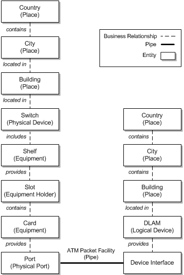
Figure 5-17 shows an example of business relationships and connectivity among entities. A Physical Port entity and a Device Interface entity are linked by a pipe. Each of the two entities is part of a hierarchy and has associations with other entities.
Figure 5-17 Business Relationships Example
Description of "Figure 5-17 Business Relationships Example"
In the UIM topology, pipes are translated into communication topology edges. The topology nodes on which a communication topology edge terminates are determined for each end by going up the hierarchy in the business model starting from the resource the pipe terminates on and proceeding to the highest level physical device or logical device. If the highest level physical device maps to a logical device, the topology edge is terminated on the topology node that represents the logical device. If no physical or logical device exists in the hierarchy, the topology edge terminates on the topology node that represents the highest level equipment entity in the equipment hierarchy.
Containment edges represent the hierarchies. Not all entity types are represented as topology nodes, however. For example, slots (Equipment Holder entities) are not represented as topology nodes. As a result, containment topology edges ignore these entities and they do not appear in the topology. For example, in Figure 5-17, the pipe terminates on a physical port on one end and on a device interface on the other end. Neither of these entities is represented by a topology node, so they will not appear in the topology model.
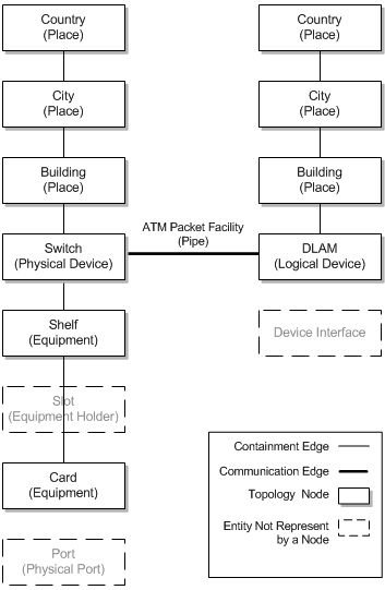
Figure 5-18 shows the topology model that is generated from the business model in Figure 5-17. A containment edge connects a card and a shelf, ignoring the slot. A connectivity topology edge representing the pipe runs between topology nodes representing the physical device (switch) on one end and the logical device (DSLAM) on the opposite end. These are the highest level physical device and logical device in the hierarchy from each end of the pipe.
Figure 5-18 Topology of Business Relationships
Description of "Figure 5-18 Topology of Business Relationships"
Connectivity is shown first at the level of the places to which connected entities are associated. In this case, that is at the level of the Place entities that represent the buildings in which the switch and DSLAM are housed. If the switch and DSLAM had been associated with the City locations, connectivity would be shown at that level.
In the first view, a black line between Place entities for buildings represents general connectivity without identifying it specifically. In the second view, the Place nodes are expanded to show the switch and the DSLAM. A green double-line represents the pipe that connects them.
Entity Identification
Most product, service, resource, and common business entities are identified in UIM with IDs that are unique by entity type. For example, you can have an Equipment entity and a Logical Device entity with the same ID, but you cannot have two Equipment entities with the same ID.
Entity IDs are a useful way to distinguish between entities of the same type that are not uniquely named. For example, you could have many different Equipment entities for interface cards with similar or identical names, but their IDs make it possible to identify them uniquely.
By default, entities that require a unique ID are set up to automatically generate IDs as they are created in UIM. The following entity types are configured for automatic ID generation by default.
-
Business interaction
-
Custom network address
-
Custom object
-
Device interface
-
Equipment holder
-
Equipment
-
Logical device
-
Logical device account
-
Media stream
-
Network
-
Party
-
Physical connector
-
Physical device
-
Physical port
-
Pipe
-
Place
-
Product
-
Service
In Design Studio, you can configure entity specifications with custom automatic ID generation that specifies exactly what numbering scheme to use. For example, you could define prefixes to designate various kinds of logical devices.You can also disable automatic ID generation so that IDs must be entered manually when entities are created in UIM. See the Design Studio Help for more information.
In addition, you can use extension points, rulesets, and Sequence specifications to further customize entity IDs. See UIM Developer's Guide for more information.
