2.7 Geometry Examples
This topic contains examples of many geometry types.
- Rectangle
- Polygon with a Hole
- Compound Line String
- Compound Polygon
- Point
- Oriented Point
- Type 0 (Zero) Element
- NURBS Curve
- Several Two-Dimensional Geometry Types
- Three-Dimensional Geometry Types
Parent topic: Spatial Data Types and Metadata
2.7.1 Rectangle
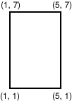
Figure 2-3 illustrates the rectangle that represents cola_a in the example in Simple Example: Inserting, Indexing, and Querying Spatial Data.
In the SDO_GEOMETRY definition of the geometry illustrated in Figure 2-3:
-
SDO_GTYPE = SDO_POLYGON2D. This indicates a two-dimensional polygon.
-
SDO_SRID = NULL.
-
SDO_POINT = NULL.
-
SDO_ELEM_INFO = (1, 1003, 3). The final 3 in 1,1003,3 indicates that this is a rectangle. Because it is a rectangle, only two ordinates are specified in SDO_ORDINATES (lower-left and upper-right).
-
SDO_ORDINATES = (1,1, 5,7). These identify the lower-left and upper-right ordinates of the rectangle.
Example 2-8 shows a SQL statement that inserts the geometry illustrated in Figure 2-3 into the database.
Example 2-8 SQL Statement to Insert a Rectangle
INSERT INTO cola_markets VALUES(
  1,
  'cola_a',
  SDO_GEOMETRY(
    SDO_POLYGON2D,  -- two-dimensional polygon
    NULL,
    NULL,
    SDO_ELEM_INFO_ARRAY(1,1003,3), -- one rectangle (1003 = exterior)
    SDO_ORDINATE_ARRAY(1,1, 5,7) -- only 2 points needed to
          -- define rectangle (lower left and upper right) with
          -- Cartesian-coordinate data
  )
);
Parent topic: Geometry Examples
2.7.2 Polygon with a Hole
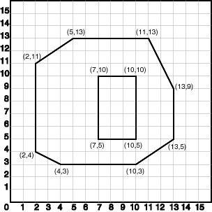
Figure 2-4 illustrates a polygon consisting of two elements: an exterior polygon ring and an interior polygon ring. The inner element in this example is treated as a void (a hole).
In the SDO_GEOMETRY definition of the geometry illustrated in Figure 2-4:
-
SDO_GTYPE = SDO_POLYGON2D. This indicates a two-dimensional polygon.
-
SDO_SRID = NULL.
-
SDO_POINT = NULL.
-
SDO_ELEM_INFO = (1,1003,1, 19,2003,1). There are two triplet elements: 1,1003,1 and 19,2003,1.
1003 indicates that the element is an exterior polygon ring; 2003 indicates that the element is an interior polygon ring.
19 indicates that the second element (the interior polygon ring) ordinate specification starts at the 19th number in the SDO_ORDINATES array (that is, 7, meaning that the first point is 7,5).
-
SDO_ORDINATES = (2,4, 4,3, 10,3, 13,5, 13,9, 11,13, 5,13, 2,11, 2,4, 7,5, 7,10, 10,10, 10,5, 7,5).
-
The area (SDO_GEOM.SDO_AREA function) of the polygon is the area of the exterior polygon minus the area of the interior polygon. In this example, the area is 84 (99 - 15).
-
The perimeter (SDO_GEOM.SDO_LENGTH function) of the polygon is the perimeter of the exterior polygon plus the perimeter of the interior polygon. In this example, the perimeter is 52.9193065 (36.9193065 + 16).
Example 2-9 SQL Statement to Insert a Polygon with a Hole
Example 2-9 shows a SQL statement that inserts the geometry illustrated in Figure 2-4 into the database.
INSERT INTO cola_markets VALUES(
  10,
  'polygon_with_hole',
  SDO_GEOMETRY(
    SDO_POLYGON2D,  -- two-dimensional polygon
    NULL,
    NULL,
    SDO_ELEM_INFO_ARRAY(1,1003,1, 19,2003,1), -- polygon with hole
    SDO_ORDINATE_ARRAY(2,4, 4,3, 10,3, 13,5, 13,9, 11,13, 5,13, 2,11, 2,4,
        7,5, 7,10, 10,10, 10,5, 7,5)
  )
);
An example of such a "polygon with a hole" might be a land mass (such as a country or an island) with a lake inside it. Of course, an actual land mass might have many such interior polygons: each one would require a triplet element in SDO_ELEM_INFO, plus the necessary ordinate specification.
Exterior and interior rings cannot be nested. For example, if a country has a lake and there is an island in the lake (and perhaps a lake on the island), a separate polygon must be defined for the island; the island cannot be defined as an interior polygon ring within the interior polygon ring of the lake.
In a multipolygon (polygon collection), rings must be grouped by polygon, and the first ring of each polygon must be the exterior ring. For example, consider a polygon collection that contains two polygons (A and B):
-
Polygon A (one interior "hole"): exterior ring A0, interior ring A1
-
Polygon B (two interior "holes"): exterior ring B0, interior ring B1, interior ring B2
The elements in SDO_ELEM_INFO and SDO_ORDINATES must be in one of the following orders (depending on whether you specify Polygon A or Polygon B first):
-
A0, A1; B0, B1, B2
-
B0, B1, B2; A0, A1
Parent topic: Geometry Examples
2.7.3 Compound Line String
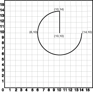
Figure 2-5 illustrates a crescent-shaped object represented as a compound line string made up of one straight line segment and one circular arc. Four points are required to represent this shape: points (10,10) and (10,14) describe the straight line segment, and points (10,14), (6,10), and (14,10) describe the circular arc.
In the SDO_GEOMETRY definition of the geometry illustrated in Figure 2-5:
-
SDO_GTYPE = SDO_CURVE2D. The first indicates a two-dimensional line segment.
-
SDO_SRID = NULL.
-
SDO_POINT = NULL.
-
SDO_ELEM_INFO = (1,4,2, 1,2,1, 3,2,2). There are three triplet elements: 1,4,2, 1,2,1, and 3,2,2.
The first triplet indicates that this element is a compound line string made up of two subelement line strings, which are described with the next two triplets.
The second triplet indicates that the line string is made up of straight line segments and that the ordinates for this line string start at offset 1. The end point of this line string is determined by the starting offset of the second line string, 3 in this instance.
The third triplet indicates that the second line string is made up of circular arcs with ordinates starting at offset 3. The end point of this line string is determined by the starting offset of the next element or the current length of the SDO_ORDINATES array, if this is the last element.
-
SDO_ORDINATES = (10,10, 10,14, 6,10, 14,10).
Example 2-10 shows a SQL statement that inserts the geometry illustrated in Figure 2-5 into the database.
Example 2-10 SQL Statement to Insert a Compound Line String
INSERT INTO cola_markets VALUES(
  11,
  'compound_line_string',
  SDO_GEOMETRY(
    SDO_CURVE2D,
    NULL,
    NULL,
    SDO_ELEM_INFO_ARRAY(1,4,2, 1,2,1, 3,2,2), -- compound line string
    SDO_ORDINATE_ARRAY(10,10, 10,14, 6,10, 14,10)
  )
);
Parent topic: Geometry Examples
2.7.4 Compound Polygon
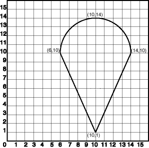
Figure 2-6 illustrates an ice cream cone-shaped object represented as a compound polygon made up of one straight line segment and one circular arc. Five points are required to represent this shape: points (6,10), (10,1), and (14,10) describe one acute angle-shaped line string, and points (14,10), (10,14), and (6,10) describe the circular arc. The starting point of the line string and the ending point of the circular arc are the same point (6,10). The SDO_ELEM_INFO array contains three triplets for this compound line string. These triplets are {(1,1005,2), (1,2,1), (5,2,2)}.
In the SDO_GEOMETRY definition of the geometry illustrated in Figure 2-6:
-
SDO_GTYPE = SDO_POLYGON2D. This indicates a two-dimensional polygon.
-
SDO_SRID = NULL.
-
SDO_POINT = NULL.
-
SDO_ELEM_INFO = (1,1005,2, 1,2,1, 5,2,2). There are three triplet elements: 1,1005,2, 1,2,1, and 5,2,2.
The first triplet indicates that this element is a compound polygon made up of two subelement line strings, which are described using the next two triplets.
The second triplet indicates that the first subelement line string is made up of straight line segments and that the ordinates for this line string start at offset 1. The end point of this line string is determined by the starting offset of the second line string, 5 in this instance. Because the vertices are two-dimensional, the coordinates for the end point of the first line string are at ordinates 5 and 6.
The third triplet indicates that the second subelement line string is made up of a circular arc with ordinates starting at offset 5. The end point of this line string is determined by the starting offset of the next element or the current length of the SDO_ORDINATES array, if this is the last element.
-
SDO_ORDINATES = (6,10, 10,1, 14,10, 10,14, 6,10).
Example 2-11 shows a SQL statement that inserts the geometry illustrated in Figure 2-6 into the database.
Example 2-11 SQL Statement to Insert a Compound Polygon
INSERT INTO cola_markets VALUES(
  12,
  'compound_polygon',
  SDO_GEOMETRY(
    SDO_POLYGON2D,  -- two-dimensional polygon
    NULL,
    NULL,
    SDO_ELEM_INFO_ARRAY(1,1005,2, 1,2,1, 5,2,2), -- compound polygon
    SDO_ORDINATE_ARRAY(6,10, 10,1, 14,10, 10,14, 6,10)
  )
);
Parent topic: Geometry Examples
2.7.5 Point
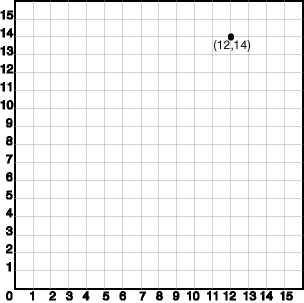
Figure 2-7 illustrates a point-only geometry at coordinates (12,14).
In the SDO_GEOMETRY definition of the geometry illustrated in Figure 2-7:
-
SDO_GTYPE = SDO_POINT2D. This indicates a two-dimensional single point.
-
SDO_SRID = NULL.
-
SDO_POINT = SDO_POINT_TYPE(12, 14, NULL). The SDO_POINT attribute is defined using the SDO_POINT_TYPE object type, because this is a point-only geometry.
For more information about the SDO_POINT attribute, see SDO_POINT.
-
SDO_ELEM_INFO and SDO_ORDINATES are both NULL, as required if the SDO_POINT attribute is specified.
Example 2-12 shows a SQL statement that inserts the geometry illustrated in Figure 2-7 into the database.
Example 2-12 SQL Statement to Insert a Point-Only Geometry
INSERT INTO cola_markets VALUES(
   90,
   'point_only',
   SDO_GEOMETRY(
      SDO_POINT2D,
      NULL,
      SDO_POINT_TYPE(12, 14, NULL),
      NULL,
      NULL));
You can search for point-only geometries based on the X, Y, and Z values in the SDO_POINT_TYPE specification. Example 2-13 is a query that asks for all points whose first coordinate (the X value) is 12, and it finds the point that was inserted in Example 2-12.
Example 2-13 Query for Point-Only Geometry Based on a Coordinate Value
SELECT * from cola_markets c WHERE c.shape.SDO_POINT.X = 12;

    MKT_ID NAME
---------- --------------------------------
SHAPE(SDO_GTYPE, SDO_SRID, SDO_POINT(X, Y, Z), SDO_ELEM_INFO, SDO_ORDINATES)
--------------------------------------------------------------------------------
        90 point_only
SDO_GEOMETRY(2001, NULL, SDO_POINT_TYPE(12, 14, NULL), NULL, NULL)
Parent topic: Geometry Examples
2.7.6 Oriented Point
An oriented point is a special type of point geometry that includes coordinates representing the locations of the point and a virtual end point, to indicate an orientation vector that can be used for rotating a symbol at the point or extending a label from the point. The main use for an oriented point is in map visualization and display applications that include symbols, such as a shield symbol to indicate a highway.
To specify an oriented point:
-
Use an SDO_GTYPE value (explained in SDO_GTYPE) for a point or multipoint geometry.
-
Specify a null value for the SDO_POINT attribute.
-
In the SDO_ELEM_INFO array (explained in SDO_ELEM_INFO), specify an additional triplet, with the second and third values (SDO_ETYPE and SDO_INTERPRETATION) as 1 and 0. For example, a triplet of 3,1,0 indicates that the point is an oriented point, with the third number in the SDO_ORDINATES array being the first coordinate, or x-axis value, of the end point reflecting the orientation vector for any symbol or label.
-
In the SDO_ORDINATES array (explained in SDO_ORDINATES), specify the coordinates of the end point for the orientation vector from the point, with values between -1 and 1. The orientation start point is assumed to be (0,0), and it is translated to the location of the physical point to which it corresponds.
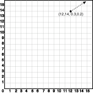
Figure 2-8 illustrates an oriented point geometry at coordinates (12,14), with an orientation vector of approximately 34 degrees (counterclockwise from the x-axis), reflecting the orientation coordinates 0.3,0.2. (To have an orientation that more precisely matches a specific angle, refer to the cotangent or tangent values in the tables in a trigonometry textbook.) The orientation vector in this example goes from (0,0) to (0.3,0.2) and extends onward. Assuming i=0.3 and j=0.2, the angle in radians can be calculated as follows: angle in radians = arctan (j/i). The angle is then applied to the physical point associated with the orientation vector.
In the SDO_GEOMETRY definition of the geometry illustrated in Figure 2-8:
-
SDO_GTYPE = SDO_POINT2D. This indicates a two-dimensional single point.
-
SDO_SRID = NULL.
-
SDO_POINT = NULL.
-
SDO_ELEM_INFO = (1,1,1, 3,1,0). The final 1,0 in 3,1,0 indicates that this is an oriented point.
-
SDO_ORDINATES = (12,14, 0.3,0.2). The 12,14 identifies the physical coordinates of the point; and the 0.3,0.2 identifies the x and y coordinates (assuming 12,14 as the origin) of the end point of the orientation vector. The resulting orientation vector slopes upward at about a 34-degree angle.
Example 2-14 shows a SQL statement that inserts the geometry illustrated in Figure 2-8 into the database.
Example 2-14 SQL Statement to Insert an Oriented Point Geometry
INSERT INTO cola_markets VALUES(
  91,
  'oriented_point',
  SDO_GEOMETRY(
    SDO_POINT2D,
    NULL,
    NULL,
    SDO_ELEM_INFO_ARRAY(1,1,1, 3,1,0),
    SDO_ORDINATE_ARRAY(12,14, 0.3,0.2)));
The following guidelines apply to the definition of an oriented point:
-
The numbers defining the orientation vector must be between -1 and 1. (In Example 2-14, these numbers are 0.3 and 0.2.)
-
Multipoint oriented points are allowed (see Example 2-15), but the orientation information must follow the point being oriented.
The following considerations apply to the dimensionality of the orientation vector for an oriented point:
-
A two-dimensional point has a two-dimensional orientation vector.
-
A two-dimensional point with an LRS measure (SDO_GTYPE=3301) has a two-dimensional orientation vector.
-
A three-dimensional point (SDO_GTYPE=SDO_POINT3D) has a three-dimensional orientation vector.
-
A three-dimensional point with an LRS measure (SDO_GTYPE=4401) has a three-dimensional orientation vector.
-
A four-dimensional point (SDO_GTYPE=4001) has a three-dimensional orientation vector.
Example 2-15 SQL Statement to Insert an Oriented Multipoint Geometry
Example 2-15 shows a SQL statement that inserts an oriented multipoint geometry into the database. The multipoint geometry contains two points, at coordinates (12,14) and (12, 10), with the two points having different orientation vectors. The statement is similar to the one in Example 2-14, but in Example 2-15 the second point has an orientation vector pointing down and to the left at 45 degrees (or, 135 degrees clockwise from the x-axis), reflecting the orientation coordinates -1,-1.
-- Oriented multipoint: 2 points, different orientations
INSERT INTO cola_markets VALUES(
  92,
  'oriented_multipoint',
  SDO_GEOMETRY(
    SDO_MULTIPOINT2D, -- Multipoint
    NULL,
    NULL,
    SDO_ELEM_INFO_ARRAY(1,1,1, 3,1,0, 5,1,1, 7,1,0),
    SDO_ORDINATE_ARRAY(12,14, 0.3,0.2, 12,10, -1,-1)));
Parent topic: Geometry Examples
2.7.7 Type 0 (Zero) Element
Type 0 (zero) elements are used to model geometry types that are not supported by Oracle Spatial, such as curves and splines. A type 0 element has an SDO_ETYPE value of 0. (See SDO_ELEM_INFO for information about the SDO_ETYPE.) Type 0 elements are not indexed by Oracle Spatial, and they are ignored by spatial functions and procedures.
Geometries with type 0 elements must contain at least one nonzero element, that is, an element with an SDO_ETYPE value that is not 0. The nonzero element should be an approximation of the unsupported geometry, and therefore it must have both:
-
An SDO_ETYPE value associated with a geometry type supported by Spatial
-
An SDO_INTERPRETATION value that is valid for the SDO_ETYPE value (see Table 2-4)
(The SDO_INTERPRETATION value for the type 0 element can be any numeric value, and applications are responsible for determining the validity and significance of the value.)
The nonzero element is indexed by Spatial, and it will be returned by the spatial index.
The SDO_GTYPE value for a geometry containing a type 0 element must be set to the value for the geometry type of the nonzero element.
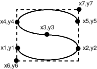
Figure 2-9 shows a geometry with two elements: a curve (unsupported geometry) and a rectangle (the nonzero element) that approximates the curve. The curve looks like the letter S, and the rectangle is represented by the dashed line.
Figure 2-9 Geometry with Type 0 (Zero) Element
Description of "Figure 2-9 Geometry with Type 0 (Zero) Element"
In the example shown in Figure 2-9:
-
The SDO_GTYPE value for the geometry is SDO_POLYGON2D (for a two-dimensional polygon).
-
The SDO_ELEM_INFO array contains two triplets for this compound line string. For example, the triplets might be {(1,0,57), (11,1003,3)}. That is:
Ordinate Starting Offset (SDO_STARTING_OFFSET) Element Type (SDO_ETYPE) Interpretation (SDO_INTERPRETATION) 1
0
57
11
1003
3
In this example:
-
The type 0 element has an SDO_ETYPE value of 0.
-
The nonzero element (rectangle) has an SDO_ETYPE value of 1003, indicating an exterior polygon ring.
-
The nonzero element has an SDO_STARTING_OFFSET value of 11 because ordinate x6 is the eleventh ordinate in the geometry.
-
The type 0 element has an SDO_INTERPRETATION value whose significance is application-specific. In this example, the SDO_INTERPRETATION value is 57.
-
The nonzero element has an SDO_INTERPRETATION value that is valid for the SDO_ETYPE of 1003. In this example, the SDO_INTERPRETATION value is 3, indicating a rectangle defined by two points (lower-left and upper-right).
Example 2-16 shows a SQL statement that inserts the geometry with a type 0 element (similar to the geometry illustrated in Figure 2-9) into the database. In the SDO_ORDINATE_ARRAY structure, the curve is defined by points (6,6), (12,6), (9,8), (6,10), and (12,10), and the rectangle is defined by points (6,4) and (12,12).
Example 2-16 SQL Statement to Insert a Geometry with a Type 0 Element
INSERT INTO cola_markets VALUES(
  13,
  'type_zero_element_geom',
  SDO_GEOMETRY(
    SDO_POLYGON2D,  -- two-dimensional polygon
    NULL,
    NULL,
    SDO_ELEM_INFO_ARRAY(1,0,57, 11,1003,3), -- 1st is type 0 element
    SDO_ORDINATE_ARRAY(6,6, 12,6, 9,8, 6,10, 12,10, 6,4, 12,12)
  )
);
Parent topic: Geometry Examples
2.7.8 NURBS Curve
A NURBS (non-uniform rational B-spline) curve allows the representation of free-form shapes with arbitrary shapes. NURBS representation allows control over the shape of the curve because control points and knots guide the shape of the curve, and they allow complex shapes to be represented with little data. For an explanation of NURBS curves and the requirements for defining a NURBS curve geometry, see NURBS Curve Support in Oracle Spatial.
Example 2-17 shows a SQL statement that inserts a NURBS curve geometry into the database.
In the SDO_GEOMETRY definition of the geometry illustrated in Example 2-17:
-
SDO_GTYPE = SDO_CURVE2D. This indicates a two-dimensional single line string.
-
SDO_SRID = NULL. Note that geodetic NURBS curves are not permitted in Oracle Spatial.
-
SDO_POINT = NULL.
-
SDO_ELEM_INFO_ARRAY = (1,2,3). The SDO_INTERPRETATION value of 3 indicates a NURBS curve.
-
In the SDO_ORDINATE_ARRAY, 3 is the degree of the NURBS curve, 7 is the number of weighted control points, and 11 in the number of knot values.
Example 2-17 SQL Statement to Insert a NURBS Curve Geometry
CREATE TABLE nurbs_test (gid  integer, geom sdo_geometry);

INSERT INTO nurbs_test values(
  1,
  SDO_GEOMETRY(
    SDO_CURVE2D,
    NULL,
    NULL,
    SDO_ELEM_INFO_ARRAY(1, 2, 3),  /* Element type 2 = SDO_ETYPE_CURVE and Interpretation value 3 = NURBS curve */
    SDO_ORDINATE_ARRAY
      (3,        /* Degree of the NURBS curve */
       7,        /* Number of weighted Control Points */
       0, 0, 1,  /* x1, y1, w1 where w1 denotes the weight of the control point and x1, y1 are weighted values. Implies the actual coordinate values have been multiplied by w1 */
       -0.5, 1, 1,
       0.2, 2, 1,
       0.5, 3.5, 1,
       0.8, 2, 1,
       0.9, 1, 1,
       0.3, 0, 1,
       11,     /* Number of knot values = Number of control points + degree + 1 */
       0, 0, 0, 0,  0.25, 0.5, 0.75, 1.0, 1.0, 1.0, 1.0)));  /* Normalized knot vector; values start at zero and end at 1. Clamped at end points as multiplicity of zero and one is 4, which is equal to the degree of the curve + 1 */
Example 2-18 SQL Statement to Insert a NURBS Compound Curve Geometry
Example 2-18 shows the insertion of a compound curve geometry that has a NURBS segment. It uses the same NURBS_TEST table created in Example 2-17 .
INSERT INTO nurbs_test VALUES(
  1,
  SDO_GEOMETRY(SDO_CURVE2D, NULL, NULL,
    SDO_ELEM_INFO_ARRAY(1, 4, 2, 1, 2, 1, 5, 2, 3),
    SDO_ORDINATE_ARRAY(-1, -1, 0, 0, 3, 7, 0, 0, 1, -0.5, 1, 1,
      0.2, 2, 1, 0.5, 3.5, 1, 0.8, 2, 1, 0.9, 1, 1, 0.3,
      0, 1, 11, 0, 0, 0, 0, 0.25, 0.5, 0.75, 1.0, 1.0, 1.0, 1.0)
    ));
In the SDO_GEOMETRY definition of the geometry illustrated in Example 2-18:
-
SDO_GTYPE = SDO_CURVE2D. This indicates a two-dimensional single line string.
-
SDO_SRID = NULL. Note that geodetic NURBS curves are not permitted in Oracle Spatial.
-
SDO_POINT = NULL.
-
SDO_ELEM_INFO_ARRAY = (1, 4, 2, 1, 2, 1, 5, 2, 3). The first triplet indicates a compound line string (interpretation = 4) with two elements. The next two triplets define the segments of the compound line string: the first segment is a line string beginning at offset 1; the second segment is a NURBS segment beginning at offset 5.
-
In the SDO_ORDINATE_ARRAY, the first 4 values define the first segment, which is a simple line string. For compound line strings containing at least one NURBS segment, the common vertices will be repeated across segments. In this example, the last point of the line string (0,0) must be equal to the first "clamped" point of the NURBS curve (0,0). The NURBS segment is defined beginning at offset 5 and the first control point is (0,0), which follows the degree (3) and the number of control points (7). The NURBS segment has 11 knot values.
Parent topic: Geometry Examples
2.7.9 Several Two-Dimensional Geometry Types
Example 2-19 creates a table and inserts various two-dimensional geometries, including multipoints (point clusters), multipolygons, and collections. At the end, it calls the SDO_GEOM.VALIDATE_GEOMETRY_WITH_CONTEXT function to validate the inserted geometries. Note that some geometries are deliberately invalid, and their descriptions include the string INVALID.
Example 2-19 SQL Statements to Insert Various Two-Dimensional Geometries
CREATE TABLE t1 (
  i NUMBER,
  d VARCHAR2(50),
  g SDO_GEOMETRY
);
INSERT INTO t1 (i, d, g)
VALUES (
  1,
  'Point',
  sdo_geometry (SDO_POINT2D, null, null, sdo_elem_info_array (1,1,1),
    sdo_ordinate_array (10,5))
);
INSERT INTO t1 (i, d, g)
VALUES (
  2,
  'Line segment',
  sdo_geometry (SDO_LINESTRING2D, null, null, sdo_elem_info_array (1,2,1),
    sdo_ordinate_array (10,10, 20,10))
);
INSERT INTO t1 (i, d, g)
VALUES (
  3,
  'Arc segment',
  sdo_geometry (SDO_LINESTRING2D, null, null, sdo_elem_info_array (1,2,2),
    sdo_ordinate_array (10,15, 15,20, 20,15))
);
INSERT INTO t1 (i, d, g)
VALUES (
  4,
  'Line string',
  sdo_geometry (SDO_LINESTRING2D, null, null, sdo_elem_info_array (1,2,1),
    sdo_ordinate_array (10,25, 20,30, 25,25, 30,30))
);
INSERT INTO t1 (i, d, g)
VALUES (
  5,
  'Arc string',
  sdo_geometry (SDO_LINESTRING2D, null, null, sdo_elem_info_array (1,2,2),
    sdo_ordinate_array (10,35, 15,40, 20,35, 25,30, 30,35))
);
INSERT INTO t1 (i, d, g)
VALUES (
  6,
  'Compound line string',
  sdo_geometry (SDO_LINESTRING2D, null, null,
    sdo_elem_info_array (1,4,3, 1,2,1, 3,2,2, 7,2,1),
    sdo_ordinate_array (10,45, 20,45, 23,48, 20,51, 10,51))
);
INSERT INTO t1 (i, d, g)
VALUES (
  7,
  'Closed line string',
  sdo_geometry (SDO_LINESTRING2D, null, null, sdo_elem_info_array (1,2,1),
    sdo_ordinate_array (10,55, 15,55, 20,60, 10,60, 10,55))
);
INSERT INTO t1 (i, d, g)
VALUES (
  8,
  'Closed arc string',
  sdo_geometry (SDO_LINESTRING2D, null, null, sdo_elem_info_array (1,2,2),
    sdo_ordinate_array (15,65, 10,68, 15,70, 20,68, 15,65))
);
INSERT INTO t1 (i, d, g)
VALUES (
  9,
  'Closed mixed line',
  sdo_geometry (SDO_LINESTRING2D, null, null, sdo_elem_info_array (1,4,2, 1,2,1, 7,2,2),
    sdo_ordinate_array (10,78, 10,75, 20,75, 20,78, 15,80, 10,78))
);
INSERT INTO t1 (i, d, g)
VALUES (
  10,
  'Self-crossing line',
  sdo_geometry (SDO_LINESTRING2D, null, null, sdo_elem_info_array (1,2,1),
    sdo_ordinate_array (10,85, 20,90, 20,85, 10,90, 10,85))
);
INSERT INTO t1 (i, d, g)
VALUES (
  11,
  'Polygon',
  sdo_geometry (SDO_POLYGON2D, null, null, sdo_elem_info_array (1,1003,1),
    sdo_ordinate_array (10,105, 15,105, 20,110, 10,110, 10,105))
);
INSERT INTO t1 (i, d, g)
VALUES (
  12,
  'Arc polygon',
  sdo_geometry (SDO_POLYGON2D, null, null, sdo_elem_info_array (1,1003,2),
    sdo_ordinate_array (15,115, 20,118, 15,120, 10,118, 15,115))
);
INSERT INTO t1 (i, d, g)
VALUES (
  13,
  'Compound polygon',
  sdo_geometry (SDO_POLYGON2D, null, null, sdo_elem_info_array (1,1005,2, 1,2,1, 7,2,2),
    sdo_ordinate_array (10,128, 10,125, 20,125, 20,128, 15,130, 10,128))
);
INSERT INTO t1 (i, d, g)
VALUES (
  14,
  'Rectangle',
  sdo_geometry (SDO_POLYGON2D, null, null, sdo_elem_info_array (1,1003,3),
    sdo_ordinate_array (10,135, 20,140))
);
INSERT INTO t1 (i, d, g)
VALUES (
  15,
  'Circle',
  sdo_geometry (SDO_POLYGON2D, null, null, sdo_elem_info_array (1,1003,4),
    sdo_ordinate_array (15,145, 10,150, 20,150))
);
INSERT INTO t1 (i, d, g)
VALUES (
  16,
  'Point cluster',
  sdo_geometry (SDO_MULTIPOINT2D, null, null, sdo_elem_info_array (1,1,3),
    sdo_ordinate_array (50,5, 55,7, 60,5))
);
INSERT INTO t1 (i, d, g)
VALUES (
  17,
  'Multipoint',
  sdo_geometry (SDO_MULTIPOINT2D, null, null, sdo_elem_info_array (1,1,1, 3,1,1, 5,1,1),
    sdo_ordinate_array (65,5, 70,7, 75,5))
);
INSERT INTO t1 (i, d, g)
VALUES (
  18,
  'Multiline',
  sdo_geometry (SDO_MULTICURVE2D, null, null, sdo_elem_info_array (1,2,1, 5,2,1),
    sdo_ordinate_array (50,15, 55,15, 60,15, 65,15))
);
INSERT INTO t1 (i, d, g)
VALUES (
  19,
  'Multiline - crossing',
  sdo_geometry (SDO_MULTICURVE2D, null, null, sdo_elem_info_array (1,2,1, 5,2,1),
    sdo_ordinate_array (50,22, 60,22, 55,20, 55,25))
);
INSERT INTO t1 (i, d, g)
VALUES (
  20,
  'Multiarc',
  sdo_geometry (SDO_MULTICURVE2D, null, null, sdo_elem_info_array (1,2,2, 7,2,2),
    sdo_ordinate_array (50,35, 55,40, 60,35, 65,35, 70,30, 75,35))
);
INSERT INTO t1 (i, d, g)
VALUES (
  21,
  'Multiline - closed',
  sdo_geometry (SDO_MULTICURVE2D, null, null, sdo_elem_info_array (1,2,1, 9,2,1),
    sdo_ordinate_array (50,55, 50,60, 55,58, 50,55, 56,58, 60,55, 60,60, 56,58))
);
INSERT INTO t1 (i, d, g)
VALUES (
  22,
  'Multiarc - touching',
  sdo_geometry (SDO_MULTICURVE2D, null, null, sdo_elem_info_array (1,2,2, 7,2,2),
    sdo_ordinate_array (50,65, 50,70, 55,68, 55,68, 60,65, 60,70))
);
INSERT INTO t1 (i, d, g)
VALUES (
  23,
  'Multipolygon - disjoint',
  sdo_geometry (SDO_MULTIPOLYGON2D, null, null, sdo_elem_info_array (1,1003,1, 11,1003,3),
    sdo_ordinate_array (50,105, 55,105, 60,110, 50,110, 50,105, 62,108, 65,112))
);
INSERT INTO t1 (i, d, g)
VALUES (
  24,
  'Multipolygon - touching',
  sdo_geometry (SDO_MULTIPOLYGON2D, null, null, sdo_elem_info_array (1,1003,3, 5,1003,3),
    sdo_ordinate_array (50,115, 55,120, 55,120, 58,122))
);
INSERT INTO t1 (i, d, g)
VALUES (
  25,
  'Multipolygon - tangent * INVALID 13351',
  sdo_geometry (SDO_MULTIPOLYGON2D, null, null, sdo_elem_info_array (1,1003,3, 5,1003,3),
    sdo_ordinate_array (50,125, 55,130, 55,128, 60,132))
);
INSERT INTO t1 (i, d, g)
VALUES (
  26,
  'Multipolygon - multi-touch',
  sdo_geometry (SDO_MULTIPOLYGON2D, null, null, sdo_elem_info_array (1,1003,1, 17,1003,1),
    sdo_ordinate_array (50,95, 55,95, 53,96, 55,97, 53,98, 55,99, 50,99, 50,95,
      55,100, 55,95, 60,95, 60,100, 55,100))
);
INSERT INTO t1 (i, d, g)
VALUES (
  27,
  'Polygon with void',
  sdo_geometry (SDO_POLYGON2D, null, null, sdo_elem_info_array (1,1003,3, 5,2003,3),
    sdo_ordinate_array (50,135, 60,140, 51,136, 59,139))
);
INSERT INTO t1 (i, d, g)
VALUES (
  28,
  'Polygon with void - reverse',
  sdo_geometry (SDO_POLYGON2D, null, null, sdo_elem_info_array (1,2003,3, 5,1003,3),
    sdo_ordinate_array (51,146, 59,149, 50,145, 60,150))
);
INSERT INTO t1 (i, d, g)
VALUES (
  29,
  'Crescent (straight lines) * INVALID 13349',
  sdo_geometry (SDO_POLYGON2D, null, null, sdo_elem_info_array (1,1003,1),
    sdo_ordinate_array (10,175, 10,165, 20,165, 15,170, 25,170, 20,165,
      30,165, 30,175, 10,175))
);
INSERT INTO t1 (i, d, g)
VALUES (
  30,
  'Crescent (arcs) * INVALID 13349',
  sdo_geometry (SDO_POLYGON2D, null, null, sdo_elem_info_array (1,1003,2),
    sdo_ordinate_array (14,180, 10,184, 14,188, 18,184, 14,180, 16,182,
      14,184, 12,182, 14,180))
);
INSERT INTO t1 (i, d, g)
VALUES (
  31,
  'Heterogeneous collection',
  sdo_geometry (SDO_COLLECTION2D, null, null, sdo_elem_info_array (1,1,1, 3,2,1, 7,1003,1),
    sdo_ordinate_array (10,5, 10,10, 20,10, 10,105, 15,105, 20,110, 10,110,
      10,105))
);
INSERT INTO t1 (i, d, g)
VALUES (
  32,
  'Polygon+void+island touch',
  sdo_geometry (SDO_MULTIPOLYGON2D, null, null,
    sdo_elem_info_array (1,1003,1, 11,2003,1, 31,1003,1),
    sdo_ordinate_array (50,168, 50,160, 55,160, 55,168, 50,168,  51,167,
      54,167, 54,161, 51,161, 51,162, 52,163, 51,164, 51,165, 51,166, 51,167,
      52,166, 52,162, 53,162, 53,166, 52,166))
);
COMMIT;
SELECT i, d, SDO_GEOM.VALIDATE_GEOMETRY_WITH_CONTEXT (g, 0.5) FROM t1;
Parent topic: Geometry Examples
2.7.10 Three-Dimensional Geometry Types
Note:
Three-dimensional geometry operations are supported only if Oracle JVM is enabled on your Oracle Autonomous AI Database Serverless deployments. To enable Oracle JVM, see Use Oracle Java in Using Oracle Autonomous AI Database Serverless for more information.Example 2-20 creates several tables (POINTS3D, LINES3D, and POLYGONS3D), and inserts three-dimensional objects into each table as appropriate (points into POINTS3D; lines into LINES3D; and polygons, surfaces, and solids into POLYGONS3D). Example 2-21 then creates the metadata and spatial indexes for the tables.
For information about support for three-dimensional geometries, see Three-Dimensional Spatial Objects.
Example 2-20 SQL Statements to Insert Three-Dimensional Geometries
create table points3d(id number, geometry sdo_geometry);
insert into points3d values(1, sdo_geometry(SDO_POINT3D,null,
             sdo_point_type(0,0,0), null, null));
insert into points3d values(2, sdo_geometry(SDO_POINT3D,null,
             sdo_point_type(1,1,1), null, null));
insert into points3d values(3, sdo_geometry(SDO_POINT3D,null,
             sdo_point_type(0,1,1), null, null));
insert into points3d values(4, sdo_geometry(SDO_POINT3D,null,
             sdo_point_type(0,0,1), null, null));
insert into points3d values(5, sdo_geometry(SDO_POINT3D,null,
             sdo_point_type(1,1,0), null, null));
insert into points3d values(6, sdo_geometry(SDO_POINT3D,null,
             sdo_point_type(1,0,1), null, null));
insert into points3d values(7, sdo_geometry(SDO_POINT3D,null,
             sdo_point_type(1,0,0), null, null));
insert into points3d values(8, sdo_geometry(SDO_POINT3D,null,
             sdo_point_type(0,1,0), null, null));
insert into points3d values(9, sdo_geometry(SDO_MULTIPOINT3D,null, null,
             sdo_elem_info_array(1,1,1, 4,1,1),
             sdo_ordinate_array(1,1,1, 0,0,0)));

create table lines3d(id number, geometry sdo_geometry);
insert into lines3d values(1, sdo_geometry(SDO_LINESTRING3D,null, null,
             sdo_elem_info_array(1,2,1),
             sdo_ordinate_array(1,1,1, 0,0,0)));
insert into lines3d values(2, sdo_geometry(SDO_LINESTRING3D,null, null,
             sdo_elem_info_array(1,2,1),
             sdo_ordinate_array(1,0,1, 0,1,0)));
insert into lines3d values(2, sdo_geometry(SDO_LINESTRING3D,null, null,
             sdo_elem_info_array(1,2,1),
             sdo_ordinate_array(0,1,1, 1,0,0)));
insert into lines3d values(3, sdo_geometry(SDO_LINESTRING3D,null, null,
             sdo_elem_info_array(1,2,1),
             sdo_ordinate_array(0,1,1, 1,0,0)));
insert into lines3d values(4, sdo_geometry(SDO_LINESTRING3D,null, null,
             sdo_elem_info_array(1,2,1),
             sdo_ordinate_array(0,1,0, 1,0,1)));

create table polygons3d(id number, geometry sdo_geometry);

-- Simple Polygon
-- All points have to be on the same plane.
insert into polygons3d values(1,
SDO_Geometry (SDO_POLYGON3D,NULL,NULL ,
 SDO_Elem_Info_Array(1,1003,1),
 SDO_Ordinate_Array(0.5,0.0,0.0,
0.5,1.0,0.0,
0.0,1.0,1.0,
0.0,0.0,1.0,
0.5,0.0,0.0
)));
insert into polygons3d values(2,
SDO_Geometry (SDO_POLYGON3D,NULL,NULL ,
 SDO_Elem_Info_Array(1,1003,1),
 SDO_Ordinate_Array(6.0,6.0,6.0,
5.0,6.0,10.0,
3.0,4.0,8.0,
4.0,4.0,4.0,
6.0,6.0,6.0
)));
insert into polygons3d values(3,
SDO_Geometry (SDO_MULTIPOLYGON3D,NULL,NULL ,
 SDO_Elem_Info_Array(1,1003,1,16,1003,1),
 SDO_Ordinate_Array(6.0,6.0,6.0,
5.0,6.0,10.0,
3.0,4.0,8.0,
4.0,4.0,4.0,
6.0,6.0,6.0,
0.5,0.0,0.0,
0.5,1.0,0.0,
0.0,1.0,1.0,
0.0,0.0,1.0,
0.5,0.0,0.0
)));
-- Polygon with a Hole (same rules as 2D) plus all points on the same plane
insert into polygons3d values(4,
SDO_Geometry (SDO_POLYGON3D,NULL,NULL ,
 SDO_Elem_Info_Array(1,1003,1,16,2003,1),
 SDO_Ordinate_Array(0.5,0.0,0.0,
0.5,1.0,0.0,
0.0,1.0,1.0,
0.0,0.0,1.0,
0.5,0.0,0.0,
0.25,0.5,0.5,
0.15,0.5,0.7,
0.15,0.6,0.7,
0.25,0.6,0.5,
0.25,0.5,0.5
)));
-- Surface with 2 3D polygons (on same plane)
insert into polygons3d values(5,
SDO_Geometry (SDO_POLYGON3D,NULL,NULL ,
 SDO_Elem_Info_Array(1,1006,2,1,1003,1,16,1003,1),
 SDO_Ordinate_Array(0.5,0.0,0.0,
0.5,1.0,0.0,
0.0,1.0,0.0,
0.0,0.0,0.0,
0.5,0.0,0.0,
1.5,0.0,0.0,
2.5,1.0,0.0,
1.5,2.0,0.0,
0.5,2.0,0.0,
0.5,0.0,0.0,
1.5,0.0,0.0
)));
-- Surface with 2 3D polygons (on two planes)
insert into polygons3d values(5,
SDO_Geometry(SDO_POLYGON3D,NULL,NULL ,
 SDO_Elem_Info_Array(1,1006,2,1,1003,3,7,1003,3),
 SDO_Ordinate_Array(2,2,2,
4,4,2,
2,2,2,
4,2,4
)));
-- Surface with 2 3D polygons
-- First polygon has one ext and one int.
insert into polygons3d values(6,
SDO_Geometry (SDO_POLYGON3D,NULL,NULL ,
 SDO_Elem_Info_Array(1,1006,2,1,1003,1,16,2003,1,31,1003,1),
 SDO_Ordinate_Array(0.5,0.0,0.0,
0.5,1.0,0.0,
0.0,1.0,1.0,
0.0,0.0,1.0,
0.5,0.0,0.0,
0.25,0.5,0.5,
0.15,0.5,0.7,
0.15,0.6,0.7,
0.25,0.6,0.5,
0.25,0.5,0.5,
1.5,0.0,0.0,
2.5,1.0,0.0,
1.5,2.0,0.0,
0.5,2.0,0.0,
0.5,0.0,0.0,
1.5,0.0,0.0
)));
--3D Surface with 3 3D polygons
insert into polygons3d values(7,
SDO_Geometry (SDO_POLYGON3D,NULL,NULL ,
 SDO_Elem_Info_Array(1,1006,3,1,1003,1,16,1003,1,34,1003,1),
 SDO_Ordinate_Array(0.5,0.0,0.0,
0.5,1.0,0.0,
0.0,1.0,1.0,
0.0,0.0,1.0,
0.5,0.0,0.0,
1.5,0.0,0.0,
2.5,1.0,0.0,
1.5,2.0,0.0,
0.5,2.0,0.0,
0.5,0.0,0.0,
1.5,0.0,0.0,
1.5,0.0,0.0,
2.5,0.0,0.0,
2.5,1.0,0.0,
1.5,0.0,0.0
)));
-- 3D surface with 3 3D polygons
insert into polygons3d values(8,
SDO_Geometry (SDO_POLYGON3D,NULL,NULL ,
 SDO_Elem_Info_Array(1,1006,3,1,1003,1,16,2003,1,31,1003,1,49,1003,1),
 SDO_Ordinate_Array(0.5,0.0,0.0,
0.5,1.0,0.0,
0.0,1.0,1.0,
0.0,0.0,1.0,
0.5,0.0,0.0,
0.25,0.5,0.5,
0.15,0.5,0.7,
0.15,0.6,0.7,
0.25,0.6,0.5,
0.25,0.5,0.5,
1.5,0.0,0.0,
2.5,1.0,0.0,
1.5,2.0,0.0,
0.5,2.0,0.0,
0.5,0.0,0.0,
1.5,0.0,0.0,
0.5,1.0,0.0,
0.5,2.0,0.0,
0.0,2.0,0.0,
0.0,1.0,0.0,
0.5,1.0,0.0
)));
-- Simple 3D polygon
insert into polygons3d values(9,
SDO_Geometry (SDO_POLYGON3D,NULL,NULL ,
 SDO_Elem_Info_Array(1,1003,1),
 SDO_Ordinate_Array(0.0,-4.0,1.0,
4.0,-4.0,1.0,
5.0,-3.0,1.0,
5.0,0.0,1.0,
3.0,1.0,1.0,
-1.0,1.0,1.0,
-3.0,0.5,1.0,
0.0,0.0,1.0,
-6.0,-2.0,1.0,
-6.0,-3.5,1.0,
-2.0,-3.5,1.0,
0.0,-4.0,1.0
)));
-- SOLID with 6 polygons
insert into polygons3d values(10,
SDO_Geometry (3008,NULL,NULL ,
 SDO_Elem_Info_Array(1,1007,1,1,1006,6,1,1003,1,16,1003,1,31,1003,1,46,1003,1,61,1003,1,76,1003,1),
 SDO_Ordinate_Array(1.0,0.0,-1.0,
1.0,1.0,-1.0,
1.0,1.0,1.0,
1.0,0.0,1.0,
1.0,0.0,-1.0,
1.0,0.0,1.0,
0.0,0.0,1.0,
0.0,0.0,-1.0,
1.0,0.0,-1.0,
1.0,0.0,1.0,
0.0,1.0,1.0,
0.0,1.0,-1.0,
0.0,0.0,-1.0,
0.0,0.0,1.0,
0.0,1.0,1.0,
1.0,1.0,-1.0,
0.0,1.0,-1.0,
0.0,1.0,1.0,
1.0,1.0,1.0,
1.0,1.0,-1.0,
1.0,1.0,1.0,
0.0,1.0,1.0,
0.0,0.0,1.0,
1.0,0.0,1.0,
1.0,1.0,1.0,
1.0,1.0,-1.0,
1.0,0.0,-1.0,
0.0,0.0,-1.0,
0.0,1.0,-1.0,
1.0,1.0,-1.0
)));
-- Simple SOLID with 6 polygons
-- All polygons are described using the optimized rectangle representation.
insert into polygons3d values(11,
SDO_Geometry (3008,NULL,NULL , SDO_Elem_Info_Array(1,1007,1,1,1006,6,1,1003,3,7,1003,3,13,1003,3,19,1003,3,25,1003,3,31,1003,3),
SDO_Ordinate_Array(1.0,0.0,-1.0,
1.0,1.0,1.0,
1.0,0.0,1.0,
0.0,0.0,-1.0,
0.0,1.0,1.0,
0.0,0.0,-1.0,
0.0,1.0,-1.0,
1.0,1.0,1.0,
0.0,0.0,1.0,
1.0,1.0,1.0,
1.0,1.0,-1.0,
0.0,0.0,-1.0
)));
-- Multi-Solid
-- Both solids use optimized representation.
insert into polygons3d values(12,
SDO_Geometry (3009,NULL,NULL ,
 SDO_Elem_Info_Array(1,1007,3,7,1007,3),
 SDO_Ordinate_Array(-2.0,1.0,3.0,
-3.0,-1.0,0.0,
0.0,0.0,0.0,
1.0,1.0,1.0
)));
-- Multi-Solid - like multipolygon in 2D
-- disjoint solids
insert into polygons3d values(13,
SDO_Geometry (3009,NULL,NULL , SDO_Elem_Info_Array(1,1007,1,1,1006,6,1,1003,1,16,1003,1,31,1003,1,46,1003,1,61,1003,1,76,1003,1,91,1007,1,91,1006,7,91,1003,1,106,1003,1,121,1003,1,136,1003,1,151,1003,1,166,1003,1,184,1003,1),
SDO_Ordinate_Array(1.0,0.0,4.0,
1.0,1.0,4.0,
1.0,1.0,6.0,
1.0,0.0,6.0,
1.0,0.0,4.0,
1.0,0.0,6.0,
0.0,0.0,6.0,
0.0,0.0,4.0,
1.0,0.0,4.0,
1.0,0.0,6.0,
0.0,1.0,6.0,
0.0,1.0,4.0,
0.0,0.0,4.0,
0.0,0.0,6.0,
0.0,1.0,6.0,
1.0,1.0,4.0,
0.0,1.0,4.0,
0.0,1.0,6.0,
1.0,1.0,6.0,
1.0,1.0,4.0,
1.0,1.0,6.0,
0.0,1.0,6.0,
0.0,0.0,6.0,
1.0,0.0,6.0,
1.0,1.0,6.0,
1.0,1.0,4.0,
1.0,0.0,4.0,
0.0,0.0,4.0,
0.0,1.0,4.0,
1.0,1.0,4.0,
2.0,0.0,3.0,
2.0,0.0,0.0,
4.0,2.0,0.0,
4.0,2.0,3.0,
2.0,0.0,3.0,
4.5,-2.0,3.0,
4.5,-2.0,0.0,
2.0,0.0,0.0,
2.0,0.0,3.0,
4.5,-2.0,3.0,
4.5,-2.0,3.0,
-2.0,-2.0,3.0,
-2.0,-2.0,0.0,
4.5,-2.0,0.0,
4.5,-2.0,3.0,
-2.0,-2.0,3.0,
-2.0,2.0,3.0,
-2.0,2.0,0.0,
-2.0,-2.0,0.0,
-2.0,-2.0,3.0,
4.0,2.0,3.0,
4.0,2.0,0.0,
-2.0,2.0,0.0,
-2.0,2.0,3.0,
4.0,2.0,3.0,
2.0,0.0,3.0,
4.0,2.0,3.0,
-2.0,2.0,3.0,
-2.0,-2.0,3.0,
4.5,-2.0,3.0,
2.0,0.0,3.0,
2.0,0.0,0.0,
4.5,-2.0,0.0,
-2.0,-2.0,0.0,
-2.0,2.0,0.0,
4.0,2.0,0.0,
2.0,0.0,0.0
)));

-- SOLID with a hole
-- etype = 1007 exterior solid
-- etype = 2007 is interior solid
-- All polygons of etype=2007 are described as 2003's.
insert into polygons3d values(14,
SDO_Geometry (3008,NULL,NULL ,
 SDO_Elem_Info_Array(1,1007,1,1,1006,7,1,1003,1,16,1003,1,31,1003,1,46,1003,1,61,1003,1,76,1003,1,94,1003,1,112,2006,6,112,2003,1,127,2003,1,142,2003,1,157,2003,1,172,2003,1,187,2003,1),
 SDO_Ordinate_Array(2.0,0.0,3.0,
2.0,0.0,0.0,
4.0,2.0,0.0,
4.0,2.0,3.0,
2.0,0.0,3.0,
4.5,-2.0,3.0,
4.5,-2.0,0.0,
2.0,0.0,0.0,
2.0,0.0,3.0,
4.5,-2.0,3.0,
4.5,-2.0,3.0,
-2.0,-2.0,3.0,
-2.0,-2.0,0.0,
4.5,-2.0,0.0,
4.5,-2.0,3.0,
-2.0,-2.0,3.0,
-2.0,2.0,3.0,
-2.0,2.0,0.0,
-2.0,-2.0,0.0,
-2.0,-2.0,3.0,
4.0,2.0,3.0,
4.0,2.0,0.0,
-2.0,2.0,0.0,
-2.0,2.0,3.0,
4.0,2.0,3.0,
2.0,0.0,3.0,
4.0,2.0,3.0,
-2.0,2.0,3.0,
-2.0,-2.0,3.0,
4.5,-2.0,3.0,
2.0,0.0,3.0,
2.0,0.0,0.0,
4.5,-2.0,0.0,
-2.0,-2.0,0.0,
-2.0,2.0,0.0,
4.0,2.0,0.0,
2.0,0.0,0.0,
1.0,1.0,2.5,
-1.0,1.0,2.5,
-1.0,1.0,0.5,
1.0,1.0,0.5,
1.0,1.0,2.5,
-1.0,1.0,2.5,
-1.0,-1.0,2.5,
-1.0,-1.0,0.5,
-1.0,1.0,0.5,
-1.0,1.0,2.5,
-1.0,-1.0,2.5,
1.0,-1.0,2.5,
1.0,-1.0,0.5,
-1.0,-1.0,0.5,
-1.0,-1.0,2.5,
1.0,-1.0,2.5,
1.0,1.0,2.5,
1.0,1.0,0.5,
1.0,-1.0,0.5,
1.0,-1.0,2.5,
-1.0,-1.0,2.5,
-1.0,1.0,2.5,
1.0,1.0,2.5,
1.0,-1.0,2.5,
-1.0,-1.0,2.5,
1.0,1.0,0.5,
-1.0,1.0,0.5,
-1.0,-1.0,0.5,
1.0,-1.0,0.5,
1.0,1.0,0.5
)));
-- Gtype = SOLID
-- The elements make up one composite solid (non-disjoint solids) like a cube
-- on a cube on a cube.
-- This is made up of two solid elements.
-- Each solid element here is a simple solid.
insert into polygons3d values(15,
SDO_Geometry (3008,NULL,NULL ,
 SDO_Elem_Info_Array(1,1008,2,1,1007,1,1,1006,6,1,1003,1,16,1003,1,31,1003,1,46,1003,1,61,1003,1,76,1003,1,91,1007,1,91,1006,7,91,1003,1,106,1003,1,121,1003,1,136,1003,1,151,1003,1,166,1003,1,184,1003,1),
 SDO_Ordinate_Array(-2.0,1.0,3.0,
-2.0,1.0,0.0,
-3.0,1.0,0.0,
-3.0,1.0,3.0,
-2.0,1.0,3.0,
-3.0,1.0,3.0,
-3.0,1.0,0.0,
-3.0,-1.0,0.0,
-3.0,-1.0,3.0,
-3.0,1.0,3.0,
-3.0,-1.0,3.0,
-3.0,-1.0,0.0,
-2.0,-1.0,0.0,
-2.0,-1.0,3.0,
-3.0,-1.0,3.0,
-2.0,-1.0,3.0,
-2.0,-1.0,0.0,
-2.0,1.0,0.0,
-2.0,1.0,3.0,
-2.0,-1.0,3.0,
-2.0,-1.0,3.0,
-2.0,1.0,3.0,
-3.0,1.0,3.0,
-3.0,-1.0,3.0,
-2.0,-1.0,3.0,
-2.0,1.0,0.0,
-2.0,-1.0,0.0,
-3.0,-1.0,0.0,
-3.0,1.0,0.0,
-2.0,1.0,0.0,
2.0,0.0,3.0,
2.0,0.0,0.0,
4.0,2.0,0.0,
4.0,2.0,3.0,
2.0,0.0,3.0,
4.5,-2.0,3.0,
4.5,-2.0,0.0,
2.0,0.0,0.0,
2.0,0.0,3.0,
4.5,-2.0,3.0,
4.5,-2.0,3.0,
-2.0,-2.0,3.0,
-2.0,-2.0,0.0,
4.5,-2.0,0.0,
4.5,-2.0,3.0,
-2.0,-2.0,3.0,
-2.0,2.0,3.0,
-2.0,2.0,0.0,
-2.0,-2.0,0.0,
-2.0,-2.0,3.0,
4.0,2.0,3.0,
4.0,2.0,0.0,
-2.0,2.0,0.0,
-2.0,2.0,3.0,
4.0,2.0,3.0,
2.0,0.0,3.0,
4.0,2.0,3.0,
-2.0,2.0,3.0,
-2.0,-2.0,3.0,
4.5,-2.0,3.0,
2.0,0.0,3.0,
2.0,0.0,0.0,
4.5,-2.0,0.0,
-2.0,-2.0,0.0,
-2.0,2.0,0.0,
4.0,2.0,0.0,
2.0,0.0,0.0
)));
Example 2-21 Updating Metadata and Creating Indexes for 3-Dimensional Geometries
Example 2-21 updates the USER_SDO_GEOM_METADATA view with the necessary information about the tables created in Example 2-20 (POINTS3D, LINES3D, and POLYGONS3D), and it creates a spatial index on the geometry column (named GEOMETRY) in each table. The indexes are created with the PARAMETERS ('sdo_indx_dims=3') clause, to ensure that all three dimensions are considered in operations that are supported on three-dimensional geometries.
INSERT INTO user_sdo_geom_metadata VALUES('POINTS3D', 'GEOMETRY',
  sdo_dim_array( sdo_dim_element('X', -100,100, 0.000005),
  sdo_dim_element('Y', -100,100, 0.000005),
  sdo_dim_element('Z', -100,100, 0.000005)), NULL);

CREATE INDEX points3d_sidx on points3d(geometry)
  INDEXTYPE IS mdsys.spatial_index_v2
  PARAMETERS ('sdo_indx_dims=3');

INSERT INTO user_sdo_geom_metadata VALUES('LINES3D', 'GEOMETRY',
  sdo_dim_array( sdo_dim_element('X', -100,100, 0.000005),
  sdo_dim_element('Y', -100,100, 0.000005),
  sdo_dim_element('Z', -100,100, 0.000005)), NULL);

CREATE INDEX lines3d_sidx on lines3d(geometry)
  INDEXTYPE IS mdsys.spatial_index_v2
  PARAMETERS ('sdo_indx_dims=3');

INSERT INTO user_sdo_geom_metadata VALUES('POLYGONS3D', 'GEOMETRY',
  sdo_dim_array( sdo_dim_element('X', -100,100, 0.000005),
  sdo_dim_element('Y', -100,100, 0.000005),
  sdo_dim_element('Z', -100,100, 0.000005)), NULL);

CREATE INDEX polygons3d_sidx on polygons3d(geometry)
  INDEXTYPE IS mdsys.spatial_index_v2
  PARAMETERS ('sdo_indx_dims=3');
Parent topic: Geometry Examples
