Performing Operations on Nodes
This topic contains sections that describe the effects of adding, moving, and removing nodes, and that explain how to perform these operations using the PL/SQL API.
Adding a Node
Adding a non-isolated node adds the node to an edge at a point that is currently on the edge. This operation also splits the edge, causing the original edge to be divided into two edges. Spatial automatically adjusts the definition of the original edge and creates a new edge (assigning it an ID value that is unique among edges in the topology).
To add a non-isolated node, use the SDO_TOPO_MAP.ADD_NODE function. To add an isolated node, use the SDO_TOPO_MAP.ADD_ISOLATED_NODE function.
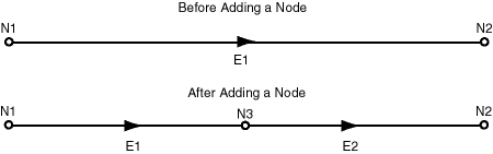
Figure: Adding a Non-Isolated Node shows the addition of a node (N3) on edge E1.
Figure: Adding a Non-Isolated Node
Description of the illustration add_node.gif
As a result of the operation shown in Figure: Adding a Non-Isolated Node:
-
Edge E1 is redefined to be between the original edge’s start point and the point at the added node (N3).
-
Edge E2 is created. Its start point is the point at node N3, and its end point is the end point of the original edge.
-
If any linear features were defined on the original edge, they are automatically redefined to be on both resulting edges, the edge is split, and a record is added to the history information table (explained in History Information Table) for the topology. For example, if a street named Main Street had been defined on the original edge E1 in Figure: Adding a Non-Isolated Node, then after the addition of node N3, Main Street would be defined on both edges E1 and E2.
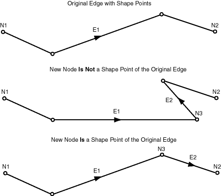
Figure: Effect of is_new_shape_point Value on Adding a Node shows a more complicated example of adding a node, where the result depends on whether or not the added node is a new shape point of the original edge (that is, on the value of the is_new_shape_point parameter to the SDO_TOPO_MAP.ADD_NODE function).
Figure: Effect of is_new_shape_point Value on Adding a Node
Description of the illustration add_node_2.gif
In Figure: Effect of is_new_shape_point Value on Adding a Node:
-
In the top part of the figure, the original edge (E1) starts at node N1, ends at node N2, and has two intermediate shape points.
-
In the middle part of the figure, a new node (N3) is added that is not a shape point of the original edge, but instead is a new shape point (that is,
is_new_shape_point=>'TRUE'). The new node is added at the location specified with thepointparameter, and is added after the vertex specified in thecoord_indexparameter (in this case,coord_index=>1to indicate after the first vertex). The new node becomes the end node for edge E1 and the start node for the new edge E2, which ends at node N2. -
In the bottom part of the figure, a new node (N3) is added that is a shape point of the original edge, and is thus not a new shape point (that is,
is_new_shape_point=>'FALSE'). Because it is not a new shape point, the node is added at the vertex specified with thecoord_indexparameter (in this case,coord_index=>2). As in the middle part of the figure, the new node becomes the end node for edge E1 and the start node for the new edge E2, which ends at node N2.
Moving a Node
Moving a non-isolated node to a new position causes the ends of all edges that are attached to the node to move with the node. You must specify the vertices for all edges affected by the moving of the node; each point (start or end) that is attached to the node must have the same coordinates as the new location of the node, and the other end points (not the moved node) of each affected edge must remain the same.
To move a non-isolated node, use the SDO_TOPO_MAP.MOVE_NODE procedure. To move an isolated node, use the SDO_TOPO_MAP.MOVE_ISOLATED_NODE procedure.
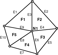
Figure: Topology Before Moving a Non-Isolated Node shows the original topology before node N1 is moved.
Figure: Topology Before Moving a Non-Isolated Node
Description of the illustration move_node_1.gif
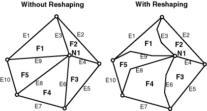
Figure: Topology After Moving a Non-Isolated Node shows two cases of the original topology after node N1 is moved. In one case, no reshaping occurs; that is, all edges affected by the movement are specified as straight lines. In the other case, reshaping occurs; that is, one or more affected edges are specified as line segments with multiple vertices.
Figure: Topology After Moving a Non-Isolated Node
Description of the illustration move_node_2b.gif
In both cases shown in Figure: Topology After Moving a Non-Isolated Node:
-
The topology does not change. That is, the number of nodes, edges, and faces does not change, and the relationships (such as adjacency and connectivity) among the nodes, edges, and faces do not change.
-
All features defined on the nodes, edges, and faces retain their definitions.
Any isolated nodes and edges might remain in the same face or be moved to a different face as a result of a move operation on a non-isolated node. The SDO_TOPO_MAP.MOVE_NODE procedure has two output parameters, moved_iso_nodes and moved_iso_edges, that store the ID numbers of any isolated nodes and edges that were moved to a different face as a result of the operation.
A node cannot be moved if, as a result of the move, any of the following would happen:
-
Any edges attached to the node would intersect any other edge. For example, assume that the original topology shown in Figure: Topology After Moving a Non-Isolated Node had included another edge E20 that passed just above and to the right of node N1. If the movement of node N1 would cause edge E3, E4, E6, E8, or E9 to intersect edge E20, the move operation is not performed.
-
The node would be moved to a face that does not currently bound the node. For example, if the movement of node N1 would place it outside the original topology shown in Figure: Topology After Moving a Non-Isolated Node, the move operation is not performed.
-
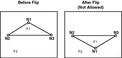
The node would be moved to the opposite side of an isolated face. This is not allowed because the move would change the topology by changing one or more of the following: the relationship or ordering of edges around the face, and the left and right face for each edge. Figure: Node Move Is Not Allowed shows a node movement (flipping node N1 from one side of isolated face F1 to the other side) that would not be allowed.
Figure Node Move Is Not Allowed
Description of the illustration flip_node.gif
Additional Examples of Allowed and Disallowed Node Moves
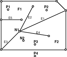
This section provides additional examples of node movement operations that are either allowed or not allowed. All refer to the topology shown in Figure: Topology for Node Movement Examples.
Figure: Topology for Node Movement Examples
Description of the illustration node_moves_several.gif
In the topology shown in Figure: Topology for Node Movement Examples:
-
Attempts will be made to move node N1 to points P1, P2, P3, and P4. (These points are locations but are not existing nodes.)
-
The edges have no shape points, either before or after the move operation.
-
New vertices are specified for the edges E1, E2, E3, and E4, but the ID values of the start and end points for the edges remain the same.
When the following node move operations are attempted using the topology shown in Figure: Topology for Node Movement Examples, the following results occur:
-
Moving node N1 to point P1: Not allowed, because one or more of the four attached edges would intersect edge E5. (Edge E3 would definitely intersect edge E5 if the move were allowed.)
-
Moving node N1 to point P2: Allowed.
-
Moving node N1 to point P3: Allowed. However, this operation causes the isolated node N2 to change from face F2 to face F1, and this might cause the application to want to roll back or disallow the movement of node N1. Similarly, if the movement of a node would cause any isolated edges or faces to change from one face to another, the application might want to roll back or disallow the node move operation.
-
Moving node N1 to point P4: Not allowed, because the node must be moved to a point in a face that bounds the original (current) position of the node.
Removing a Node
You can remove individual nodes (isolated or non-isolated), as explained in this section, and you can remove all obsolete nodes in a topology, as explained in Removing Obsolete Nodes.
Removing a non-isolated node deletes the node and merges the edges that were attached to the node into a single edge. (Spatial applies complex rules, which are not documented, to determine the ID value and direction of the resulting edge.)
To remove a non-isolated or isolated node, use the SDO_TOPO_MAP.REMOVE_NODE procedure.
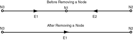
Figure: Removing a Non-Isolated Node shows the removal of a node (N1) that is attached to edges E1 and E2.
Figure: Removing a Non-Isolated Node
Description of the illustration delete_node.gif
As a result of the operation shown in Figure: Removing a Non-Isolated Node:
-
Edge E1 is redefined to consist of the line segments that had represented the original edges E1 and E2.
-
Edge E2 is deleted.
-
If any linear features were defined on both original edges, they are automatically redefined to be on the resulting edge, and a record is added to the history information table (explained in History Information Table) for the topology. For example, if a street named Main Street had been defined on the original edges E1 and E2 in Figure: Removing a Non-Isolated Node, then after the removal of node N1, Main Street would be defined on edge E1.
A node cannot be removed if one or more of the following are true:
-
A point feature is defined on the node. For example, if a point feature named Metropolitan Art Museum had been defined on node N1 in Figure: Removing a Non-Isolated Node, node N1 cannot be removed. Before you can remove the node in this case, you must remove the definition of any point features on the node.
-
A linear feature defined on either original edge is not also defined on both edges. For example, if a linear feature named Main Street had been defined on edge E1 but not edge E2 in Figure: Removing a Non-Isolated Node, node N1 cannot be removed.
Removing Obsolete Nodes
An obsolete node is a node that is connected to only two distinct edges, is not assigned to any point feature, and does not serve as the demarcation between different linear features. Obsolete nodes can result when the SDO_TOPO_MAP.ADD_POLYGON_GEOMETRY function is used repeatedly to build a topology, or when edges have been removed during editing operations, leaving some unnecessary nodes. Therefore, it is recommended that you use the SDO_TOPO_MAP.REMOVE_OBSOLETE_NODES procedure to remove obsolete nodes in such cases.
Spatial automatically updates the appropriate entries in the
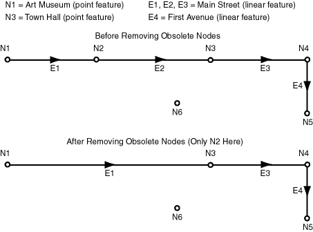
Figure: Removing Obsolete Nodes shows the removal of obsolete nodes in a simple topology. In this topology, node N1 has a point feature named Art Museum defined on it, and node N3 has a point feature named Town Hall defined on it. Edges E1, E2, and E3 have a linear feature named Main Street defined on them, and edge E4 has a linear feature named First Avenue defined on it.
Figure: Removing Obsolete Nodes
Description of the illustration delete_obsolete_nodes.gif
In Figure: Removing Obsolete Nodes, the only node removed is N2, because only that node satisfies all the criteria for an obsolete node. As for the other nodes:
-
N1 is connected to only one edge (E1), and it has a point feature defined on it (Art Museum).
-
N3 has a point feature defined on it (Town Hall).
-
N4 is the demarcation between two different linear features (Main Street and First Avenue).
-
N5 is connected to only one edge (E4).
-
Node N6 is an isolated node (not connected to any edges).
Also as a result of the operation shown in Figure: Removing Obsolete Nodes, edge E2 was removed as a result of the removal of node N2.