4 Installing Oracle Database Appliance Into a Rack
Complete the following procedures to install the Oracle Database Appliance into a rack.
- Task Overview
Tasks to perform when installing various models of Oracle Database Appliance into a rack. - Optional Component Installation
Learn about the optional components supported for the various Oracle Database Appliance models. - Safety Precautions When Rackmounting
Learn about safety precautions during rack installation for Oracle Database Appliance. - ESD Precautions
Learn about electrostatic discharge precautions during rack installation for Oracle Database Appliance. - Rack Compatibility Requirements
Learn about the basic racking requirements for installing Oracle Database Appliance. - Installing the System Into a Rack
Procedures describing how to install the various Oracle Database Appliance models into a rack.
Task Overview
Tasks to perform when installing various models of Oracle Database Appliance into a rack.
Follow the appropriate procedures to rack mount your system.
Note:
These procedures describe how to install the appliance into a rack. For cabling instructions, refer to the Deployment and User's Guide.
| Oracle Database Appliance X10-S/X10-L | Oracle Database Appliance X10-HA |
|---|---|
Parent topic: Installing Oracle Database Appliance Into a Rack
Optional Component Installation
Learn about the optional components supported for the various Oracle Database Appliance models.
Optional components can be purchased independent of the factory configuration and are shipped separately. Where possible, optional components should be installed before you install the server in a rack.
-
DIMM memory kits:
-
For Oracle Database Appliance X10-S, which comes with 256 GB (four 64 GB registered DIMMs), you have the option of expanding to 512 GB or 768 GB. Memory kits come in sets of four 64 GB registered DIMMs.
-
For Oracle Database Appliance X10-L, which comes with 512 GB (eight 64 GB registered DIMMs), you have the option of expanding to 1 TB or 1.5 TB. Memory kits come in sets of four 64 GB registered DIMMs. DIMM slots for both processors must be identically populated.
-
For Oracle Database Appliance X10-HA, which comes with 512 GB (eight x 64 GB registered DIMMs per server node), you have the option of ordering memory expansion to 1 TB or 1.5 TB per server node. Memory kits come in sets of four 64 GB registered DIMMs. DIMM slots for both server nodes must be identically populated.
Refer to the Service Manual for instructions on installing memory.
-
-
Storage drives:
-
For Oracle Database Appliance X10-L with the default configuration of two NVMe drives, you have the option of ordering two additional 2.5-inch 6.8 TB NVMe SSDs for front drive slots 2-3. Drives must be installed in pairs.
-
For Oracle Database Appliance X10-HA, you have the following options:
-
If your base configuration includes a partially populated storage shelf, you can upgrade it as follows:
-
For a high performance shelf, you can add up to eighteen 7.68 TB SSDs (available in six-packs). You can add storage with the system running and use the appliance CLI software commands to expand the storage configuration.
-
For a high capacity shelf, you can add eighteen 22 TB HDDs (available in an eighteen-pack). You must power off the appliance, add storage, then re-image and redeploy the appliance software. This is required to reconfigure the appliance from the default high performance mode to high capacity mode.
-
-
An additional storage shelf can be added if your existing appliance storage shelf came fully populated, or you expanded your partially populated base storage shelf configuration of six 7.68 TB SSDs with either eighteen 7.68 TB SSDs or eighteen 22 TB HDDs. You can add a storage expansion shelf with the system running and use the appliance CLI software commands to expand the storage configuration.
Note:
You cannot add a storage expansion shelf (which comes fully populated) unless your existing storage shelf is fully populated and the storage shelf you purchase is configured identically (same drives in same slots) to your existing storage shelf.
-
Refer to the Service Manual for instructions on installing storage drives.
-
-
Optional PCIe add-in card storage:
For Oracle Database Appliance X10-L, you have the option of ordering up to four Oracle Flash Accelerator 680 PCIe Cards per system.
Refer to the Service Manual for instructions on installing PCIe cards. After the card is replaced, refer to the Deployment and User's Guide for instructions on software configuration.
-
Optional network cards:
For Oracle Database Appliance X10 series, you have the option of ordering up to two additional public network PCIe cards per system (or per node for the X10-HA). Supported network cards include the Oracle Dual Port 25Gb Ethernet Adapter and the Oracle Quad Port 10GBase-T Adapter. Additional public network cards do not need to match public network cards (type and model) already installed.
Note:
If you intend on replacing public network cards already in the system, you need to follow the instructions in the Deyployment and User's Guide to delete the existing network card and interface via software. You cannot replace the factory installed public network card in PCIe slot 5 or the cluster interconnect card in PCIe slot 1.
Refer to the Service Manual for instructions on installing PCIe cards. After the card is replaced, refer to the Deployment and User's Guide for instructions on cabling and software configuration.
Parent topic: Installing Oracle Database Appliance Into a Rack
Safety Precautions When Rackmounting
Learn about safety precautions during rack installation for Oracle Database Appliance.
This section describes safety precautions you must follow when installing the server into a rack.
Caution:
Personal injury or equipment damage. Prevent the rack from tipping over. 1) Deploy the anti-tilt bar or legs on the equipment rack before beginning an installation. 2) Always load equipment into a rack from the bottom up so that the rack will not become top-heavy and tip over. 3) Mount equipment in the rack such that it does not create uneven or dangerous mechanical loading. 4) Do not use slide-rail mounted equipment as a shelf or workspace.
Caution:
Equipment damage caused by elevated temperature. 1) If you install the equipment in a closed or multi-unit rack assembly, ensure that the operating ambient temperature inside the rack does not exceed the maximum ambient temperature specified for the server. For server environmental requirements, see Environmental Specifications. 2) Install the equipment in the rack such that airflow is not restricted or impeded.
Caution:
Supply circuit damage and data loss. The AC circuits used to supply power to the system must be rated for the maximum amount of power that the system requires. See Electrical Specifications for input power requirements.
Caution:
Equipment damage. Maintain reliable earthing. Pay particular attention to supply connections other than direct connections to the branch circuit (for example, use of power strips).
Caution:
Equipment damage. The shipping brackets used to secure the rack cabinet to the shipping pallet are not for use in the data center for bracing or anchoring the rack cabinet during seismic events.
Parent topic: Installing Oracle Database Appliance Into a Rack
ESD Precautions
Learn about electrostatic discharge precautions during rack installation for Oracle Database Appliance.
Caution:
Equipment damage. To prevent damage from electrostatic discharge, use the following precautions when installing or servicing components.
-
Place components on an antistatic surface, such as an antistatic discharge mat, an antistatic bag, or a disposable antistatic mat.
-
Wear an antistatic grounding strap connected to a metal surface on the chassis when you work on system components.
Parent topic: Installing Oracle Database Appliance Into a Rack
Rack Compatibility Requirements
Learn about the basic racking requirements for installing Oracle Database Appliance.
The rack-mounting hardware can be used only in specialized racks that meet the requirements in the following table.
| Feature | Oracle Database Appliance X10-S/X10-L | Oracle Database Appliance X10-HA |
|---|---|---|
|
Rack structure |
Four-post rack (mounting at both front and back). Supported rack types: square hole (9.5 mm) and round hole (M6 or 1/4-20 threaded only). Two-post racks are not compatible. |
Four-post rack (mounting at both front and back). Supported rack types: square hole (9.5 mm) and round hole (M6 or 1/4-20 threaded only). Two-post racks are not compatible. |
|
Space available |
Must have 2RU (rack units) of space available. |
8RU without optional storage expansion shelf. 12RU with optional storage expansion shelf. |
|
Rack horizontal opening and unit vertical pitch |
Conforms to ANSI/EIA 310-D-1992 or IEC 60927 standards. |
Conforms to ANSI/EIA 310-D-1992 or IEC 60927 standards. |
|
Distance between front and rear mounting planes |
Minimum 610 mm and maximum 915 mm (24 in to 36 in). |
Minimum 610 mm and maximum 915 mm (24 in to 36 in). |
|
Clearance depth in front of front mounting plane |
Distance to front cabinet door is at least 25.4 mm (1 in). |
Distance to front cabinet door is at least 25.4 mm (1 in). |
|
Clearance depth behind front mounting plane |
Distance to rear cabinet door is at least 900 mm (35.43 in) with the cable management arm, or 800 mm (31.5 in) without the cable management arm. |
Distance to rear cabinet door is at least 900 mm (35.43 in) with the cable management arm, or 800 mm (31.5 in) without the cable management arm. |
|
Clearance width between front and rear mounting planes |
Distance between structural supports and cable troughs is at least 456 mm (18 in). |
Distance between structural supports and cable troughs is at least 456 mm (18 in). |
|
Minimum clearance for service access |
Front clearance: 123.2 cm (48.5 in) Rear clearance: 91 cm (36 in) |
Front clearance: 123.2 cm (48.5 in) Rear clearance: 91 cm (36 in) |
|
Server node dimensions |
Physical Specifications for Oracle Database Appliance X10 Series |
Physical Specifications for Oracle Database Appliance X10 Series |
|
Storage shelf dimensions |
N/A |
Physical Specifications for Oracle Database Appliance X10 Series |
Parent topic: Installing Oracle Database Appliance Into a Rack
Installing the System Into a Rack
Procedures describing how to install the various Oracle Database Appliance models into a rack.
Caution:
Personal injury or equipment damage. Always load equipment into a rack from the bottom up so that it will not become top-heavy and tip over. Deploy your rack's anti-tilt bar to prevent the rack from tilting during equipment installation.
- Installing Oracle Database Appliance X10-S/X10-L Into a Rack
Procedures describing how to install Oracle Database Appliance X10-S/X10-L into a rack. - Installing Oracle Database Appliance X10-HA Into a Rack
Procedures describing how to install Oracle Database Appliance X10-HA into a rack.
Parent topic: Installing Oracle Database Appliance Into a Rack
Installing Oracle Database Appliance X10-S/X10-L Into a Rack
Procedures describing how to install Oracle Database Appliance X10-S/X10-L into a rack.
- Contents of the Shipping Container
- Tools and Equipment Needed
- Stabilize the Rack for Installation
- Rackmount Kit Contents
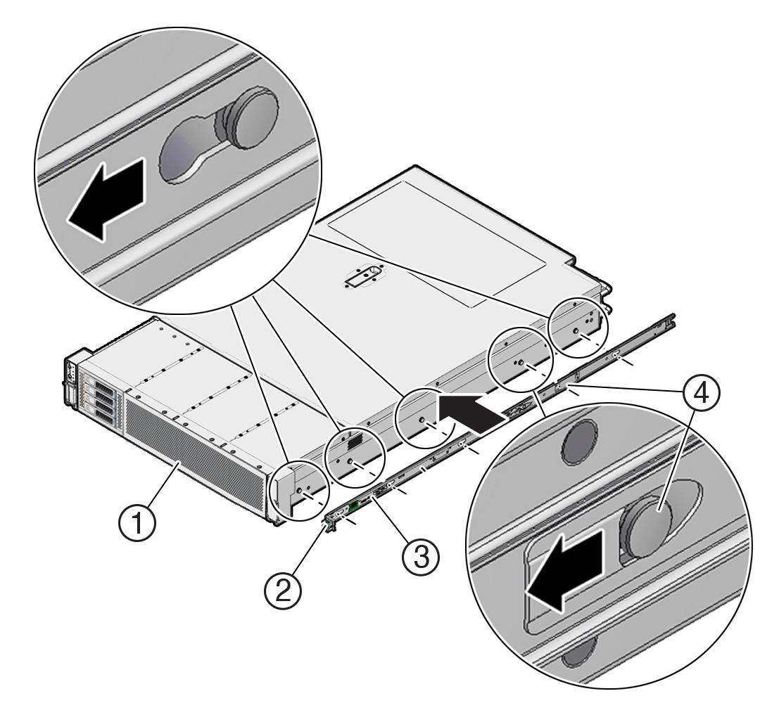
- Install Mounting Brackets on the Server
- Mark the Rackmount Location
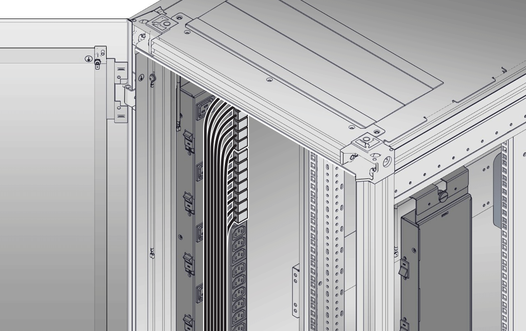
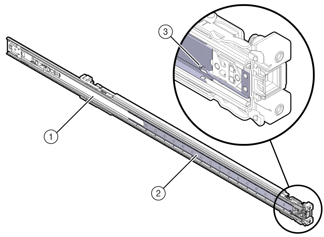
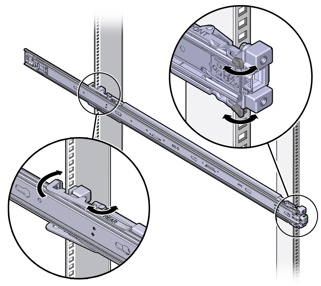
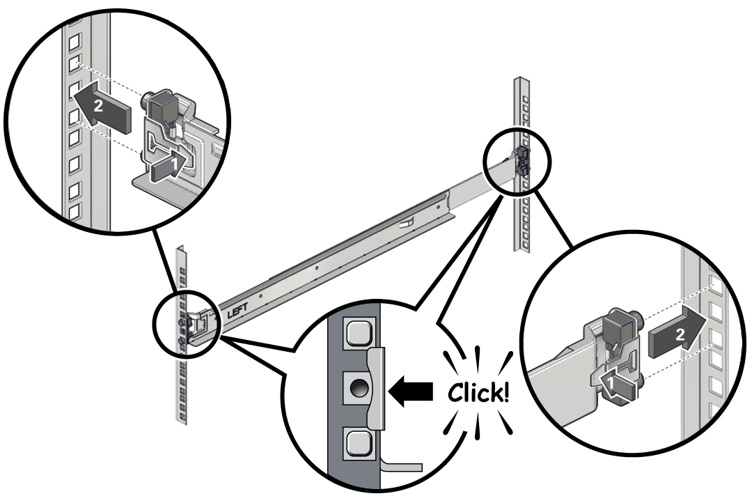
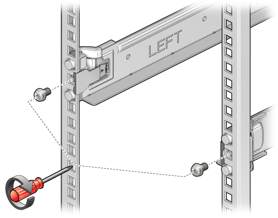
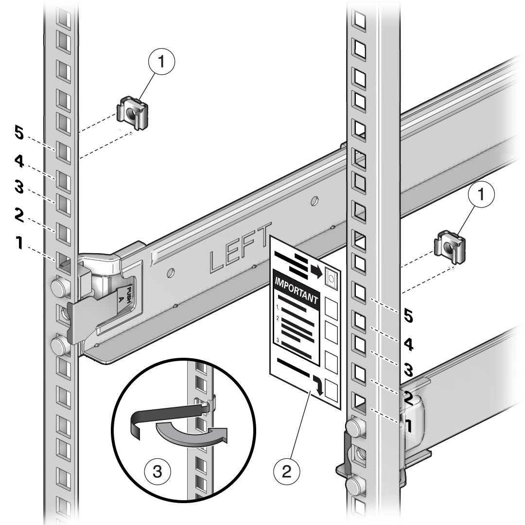
- Attach the AC Power Cables and Server Slide-Rails to the Rack
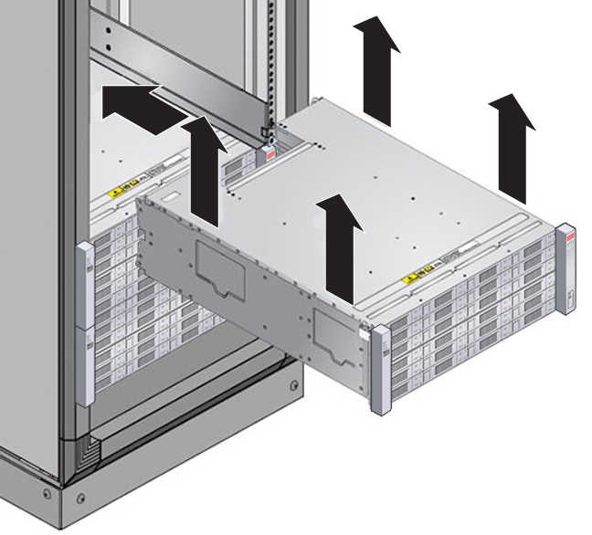
- Install the Server Into the Slide-Rail Assemblies
- Install the Cable Management Arm (Optional)
Parent topic: Installing the System Into a Rack
Contents of the Shipping Container
Inspect the shipping cartons of your Oracle Database Appliance system for evidence of physical damage. If a shipping carton appears damaged, request that the carrier's agent be present when the carton is opened. Keep all contents and packing material for the agent's inspection.
The ship kit for the server includes the following items:
-
Power cords, packaged separately with country kit
-
Rail kit containing rack rails, hardware, template and installation instructions
-
Miscellaneous hardware, cables, and connectors
-
Setup booklet
-
Legal and safety documents
Tools and Equipment Needed
Obtain the following tools and equipment before beginning the installation of Oracle Database Appliance.
-
Phillips head No. 2 screwdriver that is a minimum of 4 inches long
-
T20 Torx driver if using a threaded rack
-
A mechanical lift is highly recommended
Stabilize the Rack for Installation
Caution:
Personal injury or equipment damage. To reduce the risk of personal injury, stabilize the rack cabinet, and extend all anti-tilt devices before installing the server.
Refer to your rack cabinet documentation for more detailed instructions.
- When unpacking at the installation site, verify that the rack cabinet leveling feet are up before moving the rack cabinet.
- Remove the front and rear doors of the rack cabinet if they interfere with the installation.
- To prevent the rack cabinet from tipping during the installation, fully extend the rack cabinet's anti-tilt legs or anti-tilt bar, which are located at the bottom front of the rack cabinet.
- If there are leveling feet beneath the rack cabinet to prevent it from rolling, extend these leveling feet fully downward to the floor once the rack cabinet is where it will reside in the data center.
- When moving a rack cabinet to a different location, including repacking, verify that rack cabinet leveling feet are up before moving the rack cabinet.
Rackmount Kit Contents
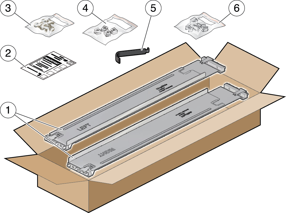
The following figure shows the Rackmount Kit contents. For additional
instructions on how to install your server in a four-post rack using the slide-rail and
cable management arm options, refer to the Rackmounting Template. 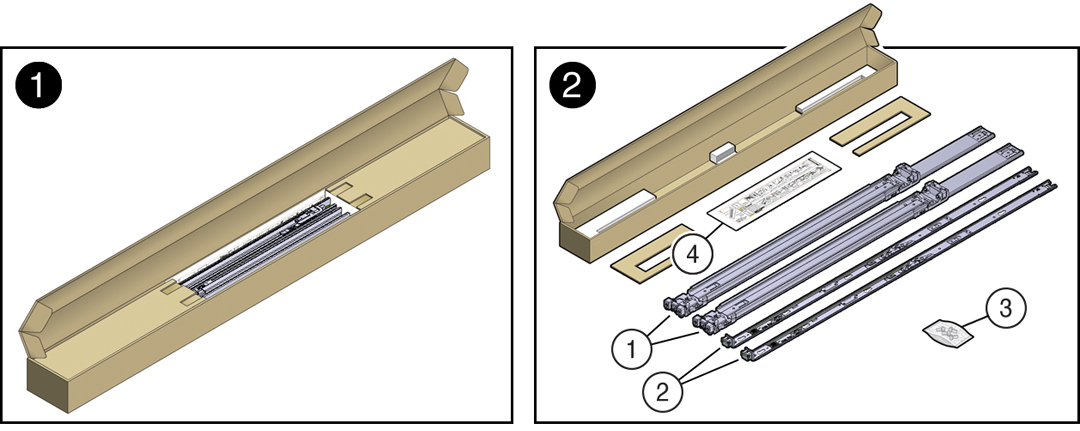
| Call Out | Description |
|---|---|
|
1 |
Slide-rails |
|
2 |
Mounting brackets |
|
3 |
Four M4 x 5 fine-pitch mounting bracket securing screws (optional) |
|
4 |
Rackmounting Template |
Install Mounting Brackets on the Server
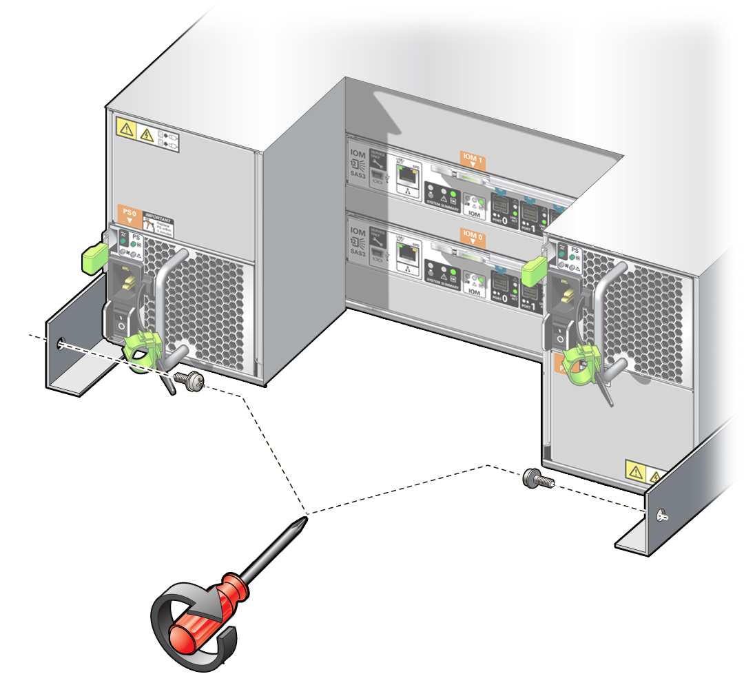
To install the mounting brackets on the sides of the server:
Mark the Rackmount Location
Identify the location in the rack where you want to place the server. Oracle Database Appliance server requires two rack units (2U). Use the Rackmounting Template to identify the correct mounting holes for the slide-rails.
Caution:
Always load equipment into a rack from the bottom up so that the rack does not become top-heavy and tip over. Extend the rack anti-tilt bar to prevent the rack from tipping during equipment installation.
- Ensure that there is at least two rack units (2U) of vertical space in the rack cabinet to install the server. See Rack Compatibility.
- Place the Rackmounting Template against the front rails, and measure up from the
bottom of the Rackmounting Template. The bottom edge of the Rackmounting Template
card corresponds to the bottom edge of the server.
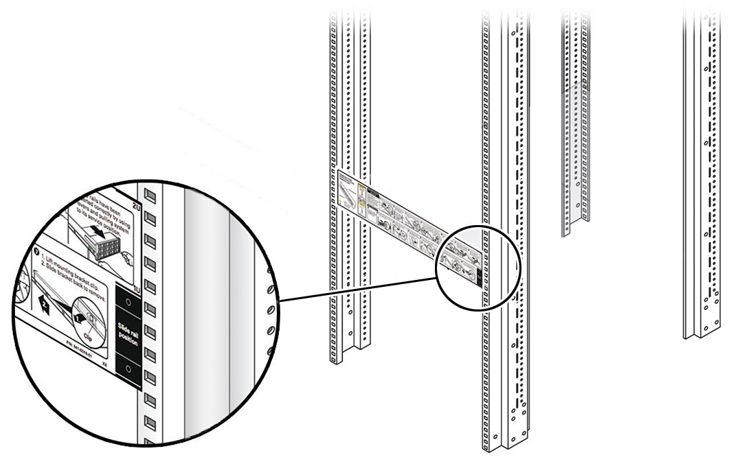
Description of the illustration mm-10237_rackmount-template.png - Mark the mounting holes for the front slide-rails.
Description of the illustration mm-10237_rackmount-template-4-drive.png - Mark the mounting holes for the back slide-rails.
Attach the AC Power Cables and Server Slide-Rails to the Rack
Use this procedure to attach the server slide-rail assemblies to the rack.
Note:
Be sure to install the server right-angle AC power cables that came with your system. In some racks, the standard rail kit slide-rails obstructs access to the front of the Power Distribution Unit (PDU) electrical sockets. Plug in your AC power cables into the PDU first, and then install the slide-rails into the rack. After you install the slide-rails, you cannot disconnect or remove the standard AC power cables from the PDU, but you can remove them from the system power supply.
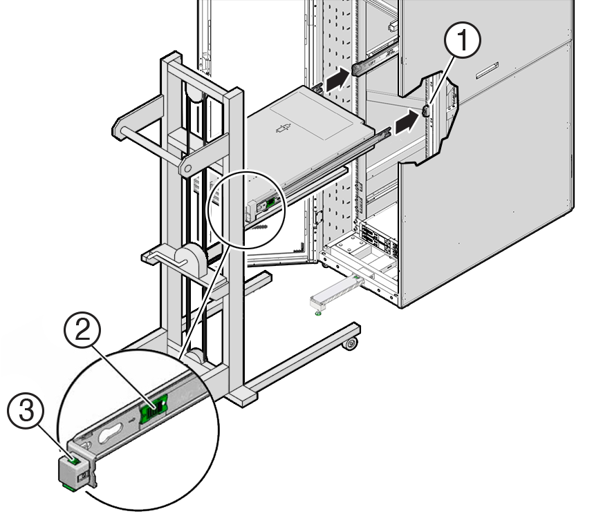
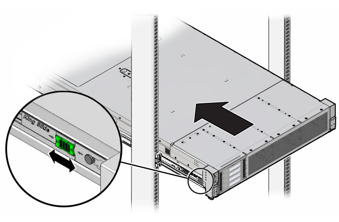
Install the Server Into the Slide-Rail Assemblies
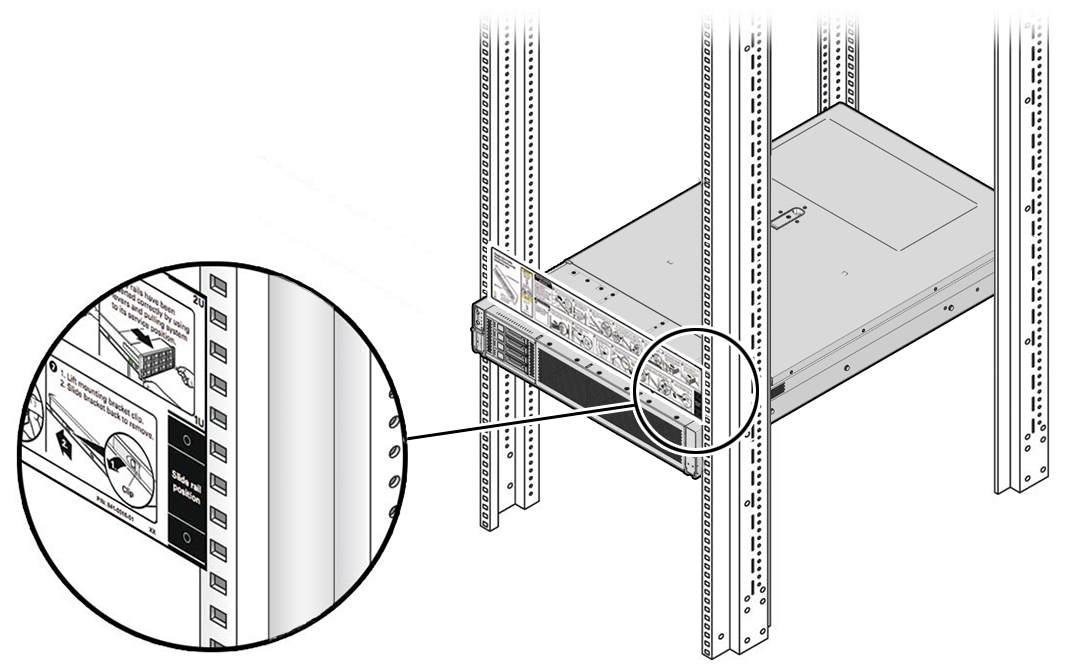
Use this procedure to install the server chassis with mounting brackets into the slide-rail assemblies that are mounted to the rack.
Caution:
Personal Injury or Equipment Damage: This procedure requires a minimum of two people because of the weight of the server. Attempting this procedure alone could result in equipment damage or personal injury.
Always load equipment into a rack from the bottom up so that the rack does not become top-heavy and tip over. Extend the rack anti-tilt bar to prevent the rack from tipping during equipment installation.
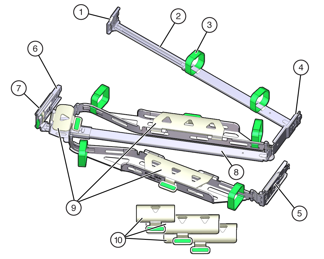
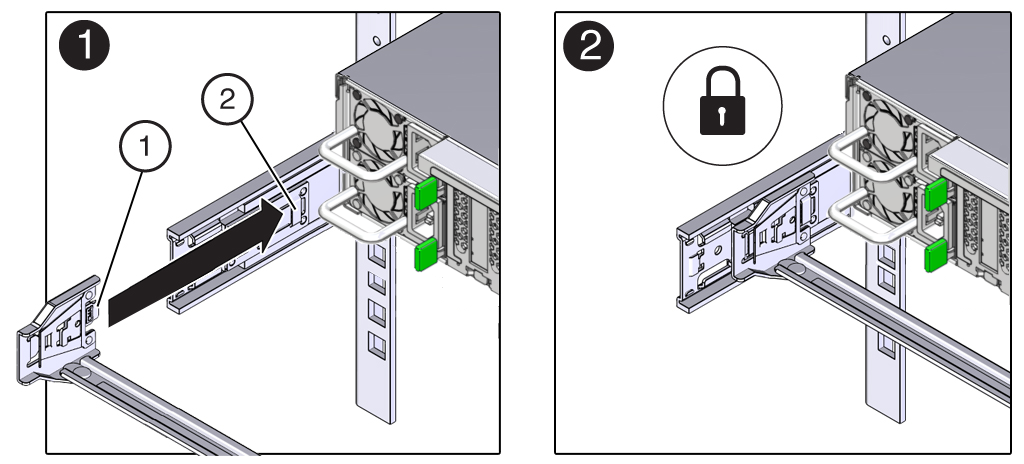
Install the Cable Management Arm (Optional)
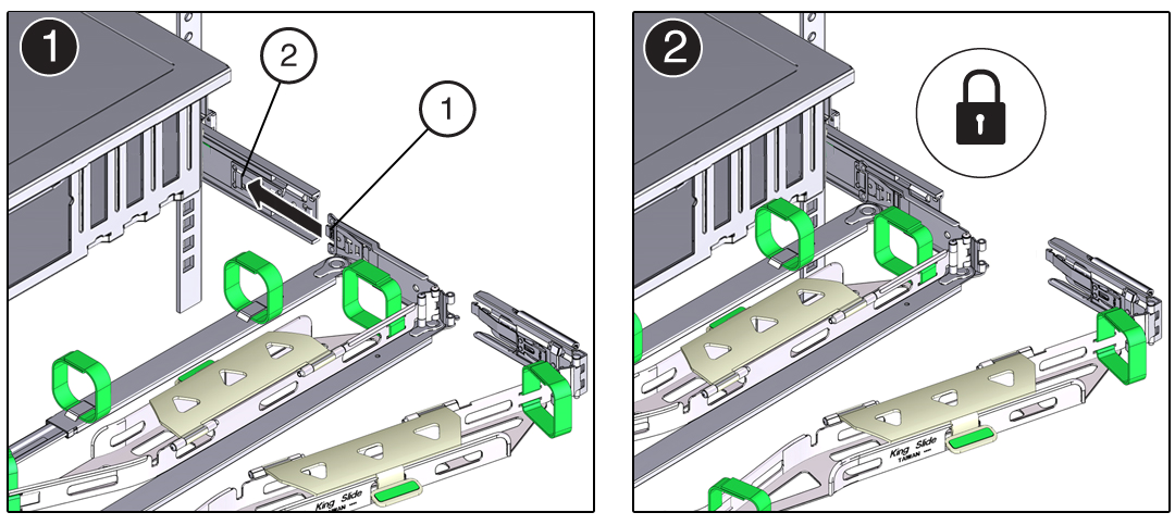
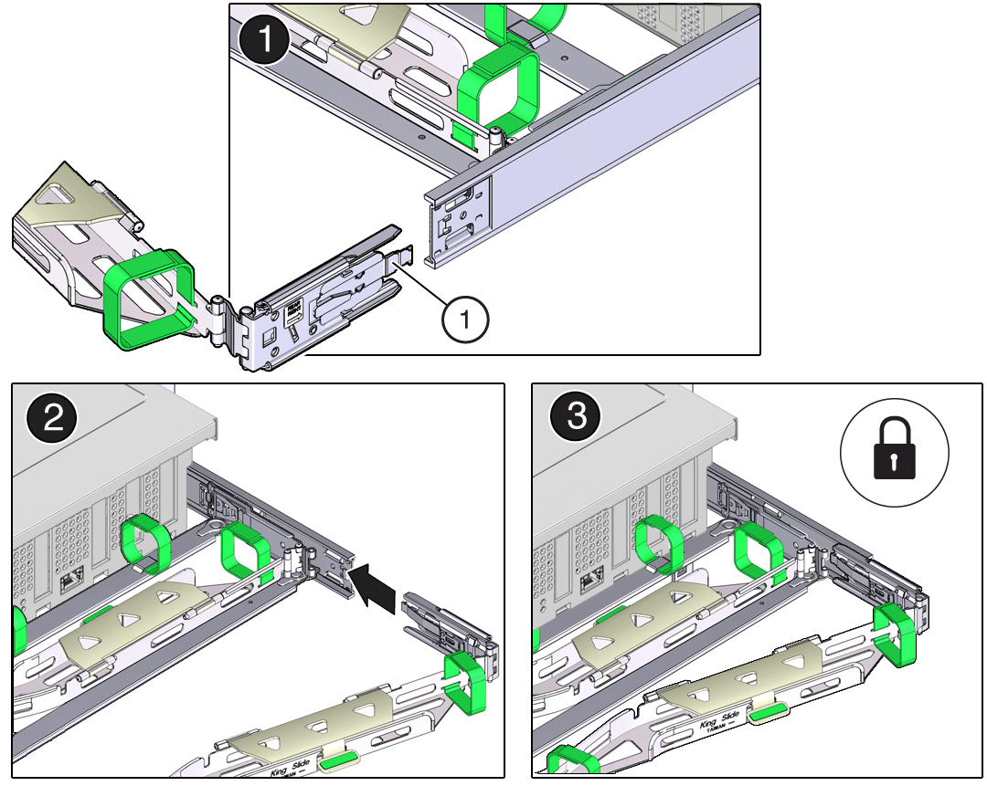
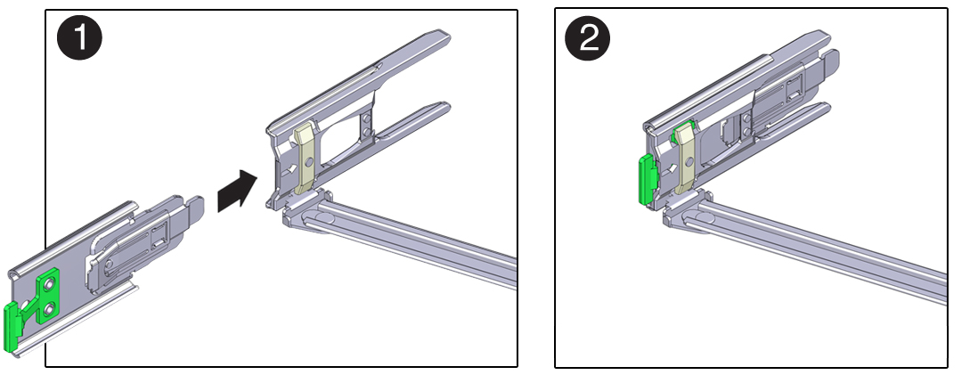
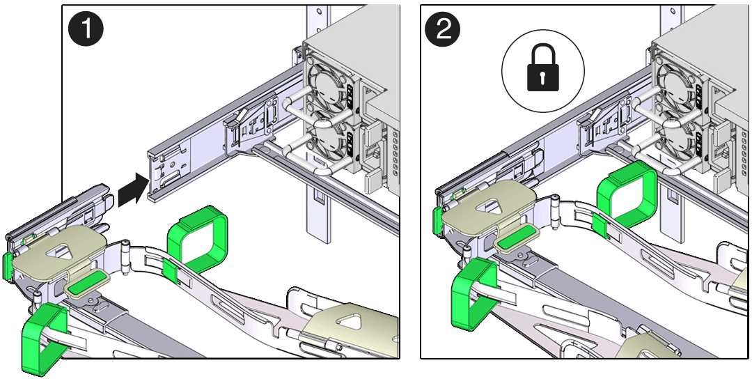
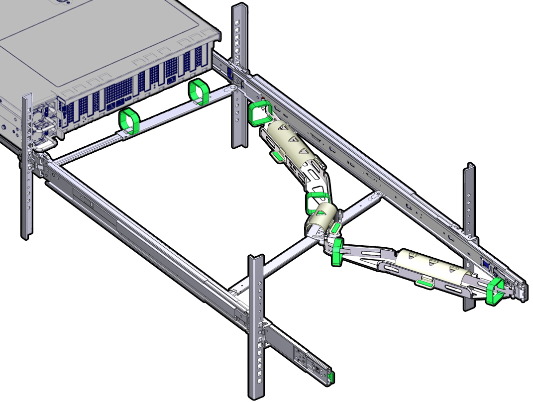
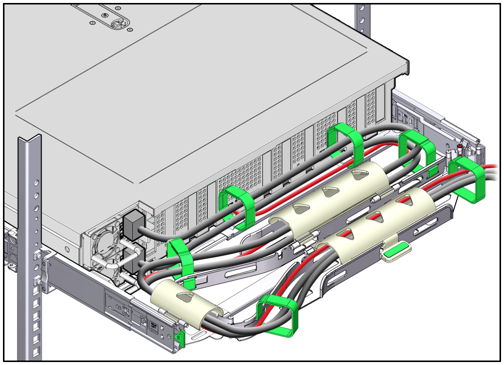
Follow this procedure to install the cable management arm (CMA), which you can use to manage cables connected to the back of the server.
Note:
Before you install the CMA, ensure that the right-angle AC power cables are long enough to connect to the rackmounted servers when routed through the CMA.
Installing Oracle Database Appliance X10-HA Into a Rack
Procedures describing how to install Oracle Database Appliance X10-HA into a rack.
Caution:
System Failure. Oracle Database Appliance is shipped with matched sets of components that must be installed together. Mixing components from different systems might cause the system to fail.
- Contents of the Shipping Container
A listing of the ship container contents of Oracle Database Appliance X10-HA. - Installation Sequence
Understand the proper installation sequence when installing an Oracle Database Appliance X10-HA into a rack. - Verify Component Compatibility
Ensure that appliance components bundled together from the factory are connected together. - Tools and Equipment Needed
A listing of the tools you will need to install Oracle Database Appliance X10-HA. - Stabilize the Rack for Installation
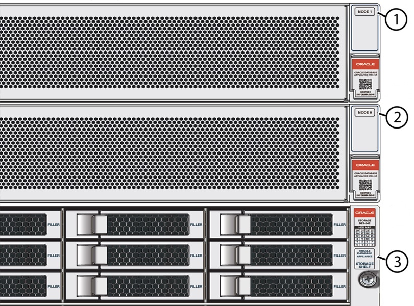
- Apply Labels to Server Nodes
Complete this task to apply server node labels before installing the appliance into a rack. - Install the Storage Shelf Into a Rack
Describes how to install an Oracle Database Appliance X10-HA storage shelf into a rack. - Add a Storage Expansion Shelf to an Existing System
Use this procedure to add a storage expansion shelf to an appliance system that is already running. - Rackmount Kit Contents
- Install Mounting Brackets on the Server
- Mark the Rackmount Location
- Attach the AC Power Cables and Server Slide-Rails to the Rack
- Install the Server Into the Slide-Rail Assemblies
- Install the Cable Management Arm (Optional)
Parent topic: Installing the System Into a Rack
Contents of the Shipping Container
A listing of the ship container contents of Oracle Database Appliance X10-HA.
For Oracle Database Appliance X10-HA, server nodes are shipped on a single pallet, and the storage shelf and storage expansion shelf are shipped separately. Each component include mounting hardware, cables, and labels.
Caution:
System failure. All items in a shipment are designed to be used together as a single system. Do not mix components from different shipments; this could cause the system to fail. For details, see Verify Component Compatibility.
The items required for your applicance include:
-
Server node 0 and server node 1 (shipped together)
-
Rackmounting hardware, cables, and labels for server nodes 0 and 1
-
One storage shelf (might be shipped separately)
-
Rackmounting hardware for the storage shelf
If you ordered an optional storage expansion shelf, it is shipped separately.
Parent topic: Installing Oracle Database Appliance X10-HA Into a Rack
Installation Sequence
Understand the proper installation sequence when installing an Oracle Database Appliance X10-HA into a rack.
Always install equipment in a rack starting at the bottom and working upwards. For Oracle Database Appliance X10-HA, install the equipment in the following order:
-
Storage expansion shelf, if equipped (lowest available rack space).
-
Storage shelf (next rack space above that).
-
Server node 0 (next rack space above that).
-
Server node 1 (next rack space above that).
Parent topic: Installing Oracle Database Appliance X10-HA Into a Rack
Verify Component Compatibility
Ensure that appliance components bundled together from the factory are connected together.
For Oracle Database Appliance X10-HA, server nodes are bundled at the factory and have a Top Level Identifier (TLI) number that is matched for the system. Both server nodes must have the same TLI. The storage shelf and storage expansion shelf will have separate TLI.
Note:
If you add a storage expansion shelf to the system after the initial installation (that is, the storage expansion shelf was not part of the initial configuration order for the appliance), its TLI will be different from the rest of the system. In this scenario, an add-on component having a different TLI from the main appliance TLI is appropriate.
Parent topic: Installing Oracle Database Appliance X10-HA Into a Rack
Tools and Equipment Needed
A listing of the tools you will need to install Oracle Database Appliance X10-HA.
Obtain the following tools and equipment before beginning the installation of Oracle Database Appliance X10-HA.
-
Phillips head No. 2 screwdriver that is a minimum of 4 inches long
-
T20 Torx driver if using a threaded rack
-
A mechanical lift is highly recommended
Caution:
Personal injury or equipment damage. The storage shelf weighs approximately 51 lbs (23 kg). If no mechanical lift is available, use three people to place it in the rack.
Parent topic: Installing Oracle Database Appliance X10-HA Into a Rack
Stabilize the Rack for Installation
Caution:
Personal injury or equipment damage. To reduce the risk of personal injury, stabilize the rack cabinet, and extend all anti-tilt devices before installing the server.
Refer to your rack cabinet documentation for more detailed instructions.
- When unpacking at the installation site, verify that the rack cabinet leveling feet are up before moving the rack cabinet.
- Remove the front and rear doors of the rack cabinet if they interfere with the installation.
- To prevent the rack cabinet from tipping during the installation, fully extend the rack cabinet's anti-tilt legs or anti-tilt bar, which are located at the bottom front of the rack cabinet.
- If there are leveling feet beneath the rack cabinet to prevent it from rolling, extend these leveling feet fully downward to the floor once the rack cabinet is where it will reside in the data center.
- When moving a rack cabinet to a different location, including repacking, verify that rack cabinet leveling feet are up before moving the rack cabinet.
Parent topic: Installing Oracle Database Appliance X10-HA Into a Rack
Apply Labels to Server Nodes
Complete this task to apply server node labels before installing the appliance into a rack.
Parent topic: Installing Oracle Database Appliance X10-HA Into a Rack
Install the Storage Shelf Into a Rack
Describes how to install an Oracle Database Appliance X10-HA storage shelf into a rack.
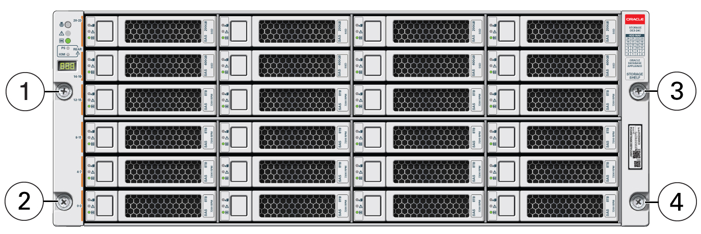
The Oracle Database Appliance X10-HA uses the Oracle Storage Drive Enclosure DE3-24C as its storage shelf. The storage shelf requires four standard mounting units (4RU) of vertical space in the cabinet.
-
Ensure that your site meets the requirements in Oracle Database Appliance Specifications
-
Ensure that the rack meets the requirements in Rack Compatibility Requirements
Note:
The rail kit included with the shelf can only be used with EIA compliant 9.5 mm square hole racks or 7.0 mm diameter round hole racks.
-
Observe all precautions in Safety Precautions When Rackmounting
Parent topic: Installing Oracle Database Appliance X10-HA Into a Rack
Add a Storage Expansion Shelf to an Existing System
Use this procedure to add a storage expansion shelf to an appliance system that is already running.
This task assumes that you are adding a storage expansion shelf to an already running Oracle Database Appliance (must already have a fully populated storage shelf).
Unless noted, it is not necessary to shut down your system to complete this task.
Please note the following exceptional conditions:
-
The storage expansion shelf normally sits at the bottom of Oracle Database Appliance, beneath the storage shelf. However, since racks should always be provisioned from the bottom up, that space might be unavailable. In these cases, to avoid re-rackmounting the entire system, it can be placed above the server nodes, or even in a different rack.
-
The Top Level Identifier (TLI) on the storage expansion shelf will not match the rest of the system as described in Verify Component Compatibility. However, adding a storage expansion shelf after your initial purchase and setup of the appliance is a supported configuration.
Parent topic: Installing Oracle Database Appliance X10-HA Into a Rack
Rackmount Kit Contents
The following figure shows the Rackmount Kit contents. For additional
instructions on how to install your server in a four-post rack using the slide-rail and
cable management arm options, refer to the Rackmounting Template. 
| Call Out | Description |
|---|---|
|
1 |
Slide-rails |
|
2 |
Mounting brackets |
|
3 |
Four M4 x 5 fine-pitch mounting bracket securing screws (optional) |
|
4 |
Rackmounting Template |
Parent topic: Installing Oracle Database Appliance X10-HA Into a Rack
Install Mounting Brackets on the Server
To install the mounting brackets on the sides of the server:
Parent topic: Installing Oracle Database Appliance X10-HA Into a Rack
Mark the Rackmount Location
Identify the location in the rack where you want to place the server. Oracle Database Appliance server requires two rack units (2U). Use the Rackmounting Template to identify the correct mounting holes for the slide-rails.
Caution:
Always load equipment into a rack from the bottom up so that the rack does not become top-heavy and tip over. Extend the rack anti-tilt bar to prevent the rack from tipping during equipment installation.
- Ensure that there is at least two rack units (2U) of vertical space in the rack cabinet to install the server. See Rack Compatibility.
- Place the Rackmounting Template against the front rails, and measure up from the
bottom of the Rackmounting Template. The bottom edge of the Rackmounting Template
card corresponds to the bottom edge of the server.

Description of the illustration mm-10237_rackmount-template.png - Mark the mounting holes for the front slide-rails.

Description of the illustration mm-10237_rackmount-template-4-drive.png - Mark the mounting holes for the back slide-rails.
Parent topic: Installing Oracle Database Appliance X10-HA Into a Rack
Attach the AC Power Cables and Server Slide-Rails to the Rack
Use this procedure to attach the server slide-rail assemblies to the rack.
Note:
Be sure to install the server right-angle AC power cables that came with your system. In some racks, the standard rail kit slide-rails obstructs access to the front of the Power Distribution Unit (PDU) electrical sockets. Plug in your AC power cables into the PDU first, and then install the slide-rails into the rack. After you install the slide-rails, you cannot disconnect or remove the standard AC power cables from the PDU, but you can remove them from the system power supply.
Parent topic: Installing Oracle Database Appliance X10-HA Into a Rack
Install the Server Into the Slide-Rail Assemblies
Use this procedure to install the server chassis with mounting brackets into the slide-rail assemblies that are mounted to the rack.
Caution:
Personal Injury or Equipment Damage: This procedure requires a minimum of two people because of the weight of the server. Attempting this procedure alone could result in equipment damage or personal injury.
Always load equipment into a rack from the bottom up so that the rack does not become top-heavy and tip over. Extend the rack anti-tilt bar to prevent the rack from tipping during equipment installation.
Parent topic: Installing Oracle Database Appliance X10-HA Into a Rack
Install the Cable Management Arm (Optional)
Follow this procedure to install the cable management arm (CMA), which you can use to manage cables connected to the back of the server.
Note:
Before you install the CMA, ensure that the right-angle AC power cables are long enough to connect to the rackmounted servers when routed through the CMA.
Parent topic: Installing Oracle Database Appliance X10-HA Into a Rack
