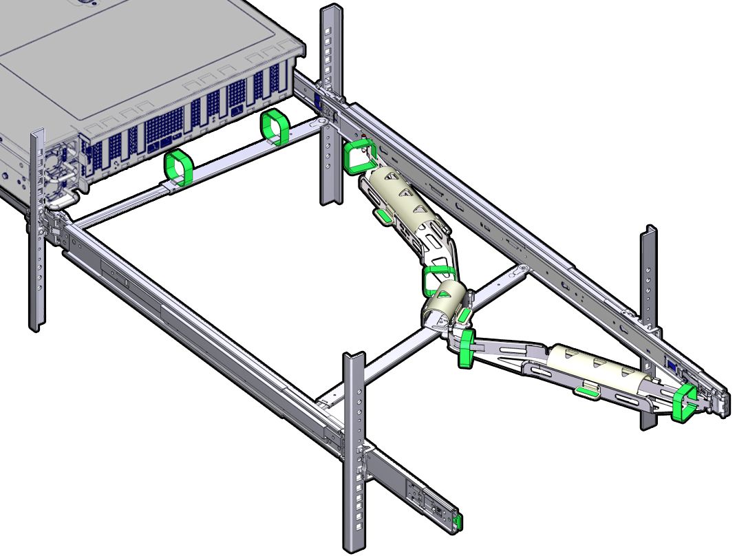
- Service Manual
- Returning Oracle Database Appliance to Operation
6 Returning Oracle Database Appliance to Operation
Perform tasks to return the Oracle Database Appliance to operation after service.
Install the Air Baffle
-
Install the air baffle by placing it into the server and lowering it to its inserted position.
To install the air baffle, the baffle must fit around the processor heatsinks, then lifted up about 50 degrees. Locate the tabs on the air baffle so that one tab on each side is under the lip of the fan tray, and the others are on top of the fan tray.
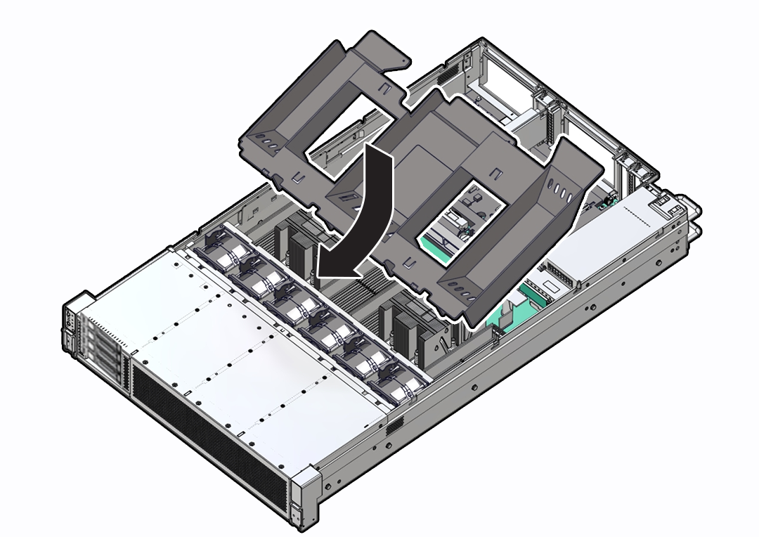
Description of the illustration aog-54_install-air-baffle.png -
Consider your next step:
-
If you removed the air baffle as part of another procedure, return to that procedure.
-
Otherwise, continue to with this procedure.
-
-
Return the server to operation:
- Install the server top cover.
- Return the server to the normal rack position.
- Reconnect the power cords and data cables to the server.
- Power on the server.
- Verify that the power supply AC OK LED is lit.
Parent topic: Returning Oracle Database Appliance to Operation
Install the Server Top Cover
-
Place the top cover on the chassis [1].
-
Set the cover down so that it hangs over the back of the server by about 1 inch (25 mm) and the side latches align with the cutouts in the chassis.
-
Check both sides of the chassis to ensure that the top cover is fully down and flush with the chassis. If the cover is not fully down and flush with the chassis, slide the cover towards the back of the chassis to position the cover in the correct position.
-
Gently slide the cover toward the front of the chassis. As you slide the cover toward the front of the server, the release button on the top of the server automatically rotates downward to the closed position.
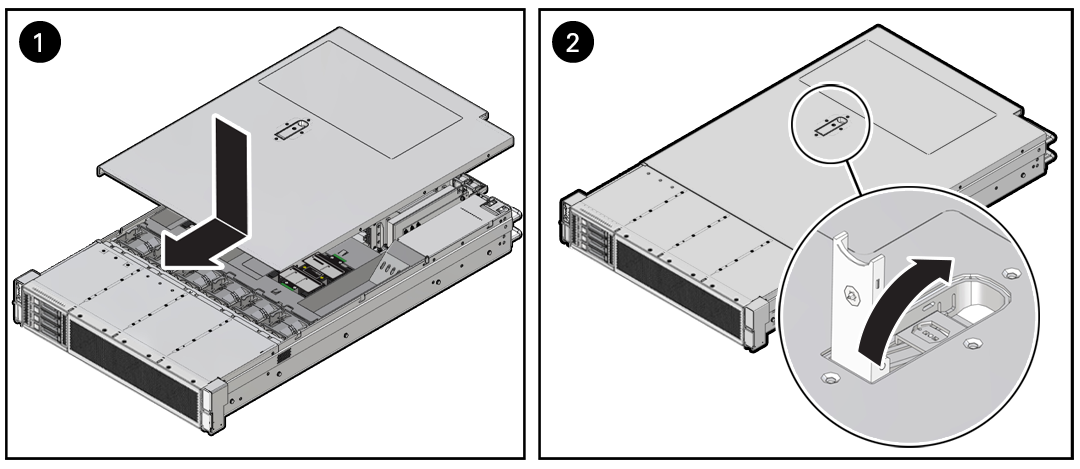
Description of the illustration mm-10866_4-drive-install-cover.png -
- Latch the top cover closed by pushing down on the button until it is flush with the
cover and you hear an audible click [2].
An audible click indicates that the cover is latched.
- Use a Torx T15 screwdriver to turn the release button latch counter-clockwise to the locked position.
Parent topic: Returning Oracle Database Appliance to Operation
Remove Antistatic Measures
- Remove any antistatic straps or conductors from the server chassis.
Parent topic: Returning Oracle Database Appliance to Operation
Reinstall the Server Into the Rack
Use this procedure to install the server chassis with mounting brackets into the slide-rail assemblies that are mounted to the rack.
Caution:
Personal Injury or Equipment Damage: This procedure requires a minimum of two people because of the weight of the server. Attempting this procedure alone could result in equipment damage or personal injury.
Always load equipment into a rack from the bottom up so that the rack does not become top-heavy and tip over. Extend the rack anti-tilt bar to prevent the rack from tipping during equipment installation.
- To prevent the rack from tipping forward when the server is extended, extend all
rack anti-tilt mechanisms.
See Stabilize the Rack.
- Push the slide-rails as far as possible into the slide-rail assemblies in the rack.
- Position the server so that the back ends of the mounting brackets are aligned with the slide-rail assemblies that are mounted in the rack.
- Insert the mounting brackets into the slide-rails, and then push the server into
the rack until the mounting brackets are flush with the slide-rail stops
(approximately 30 cm or 12 inches).
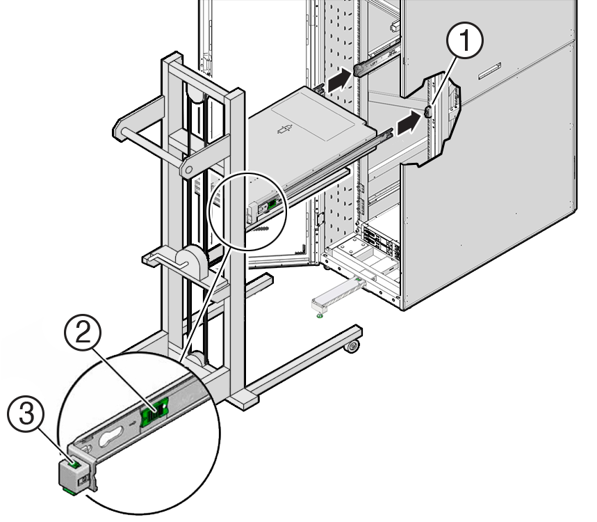
Description of the illustration aog-250_server-mtng-brkt-rack.pngCall Out Description 1
Inserting mounting bracket into slide-rail
2
Slide-rail release button
3
Slide-rail lock
- Simultaneously push and hold the green slide-rail release buttons on each mounting
bracket while you push the server into the rack. Continue pushing the server into the
rack until the slide-rail locks (on the front of the mounting brackets) engage the
slide-rail assemblies with an audible click.
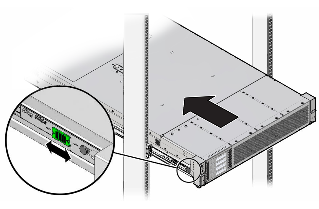
Description of the illustration aog-248_maint-position-latch-release.png
Caution:
Before you install the optional cable management arm verify that the server is securely mounted in the rack and that the slide-rail locks are engaged with the mounting brackets.
- If you extended the rack anti-tilt mechanism to stabalize the rack, retract it back to its normal position.
Parent topic: Returning Oracle Database Appliance to Operation
Return the Server to the Normal Rack Position
If the server is in the extended maintenance position, use this procedure to return the server to the normal rack position.
-
Push the server back into the rack, as described in the following steps.
-
Simultaneously pull and hold the two green release tabs (one on each side of the slide rails on the server) toward the front of the server, while you push the server into the rack.
Verify that the cable management arm (CMA) retracts without binding.
Note:
To pull the green release tab, place your finger in the center of the tab, not on the end, and apply pressure as you pull the tab toward the front of the server.
Description of the illustration aog-248_maint-position-latch-release.png -
Continue pushing the server into the rack until the slide-rail locks (on the front of the server) engage the slide-rail assemblies.
You hear an audible click when the server is in the normal rack position.
-
Simultaneously pull and hold the two green release tabs (one on each side of the slide rails on the server) toward the front of the server, while you push the server into the rack.
- Do one of the following:
- If you previously removed the CMA, proceed to the next section to reinstall it. See Install the Cable Management Arm (Optional).
- If you did not remove or purchase the optional cable management arm, retract the rack anti-tilt mechanism back to its normal position.
Parent topic: Returning Oracle Database Appliance to Operation
Install the Cable Management Arm (Optional)
Follow this procedure to install the cable management arm (CMA), which you can use to manage cables connected to the back of the server.
Note:
Before you install the CMA, ensure that the right-angle AC power cables are long enough to connect to the rackmounted servers when routed through the CMA.
-
Unpack the CMA, which contains the following components.
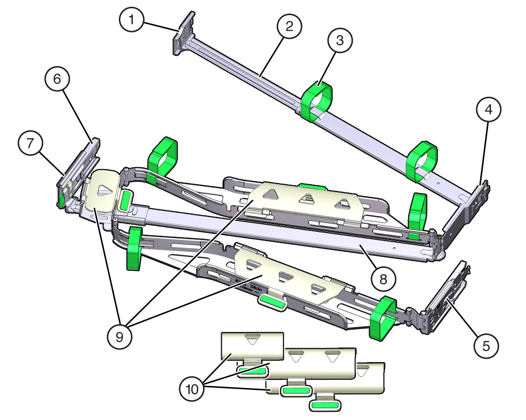
Description of the illustration a2484_cma_components.jpg
Call Out Description 1
Connector A
2
Front slide bar
3
Velcro straps (6)
4
Connector B
5
Connector C
6
Connector D
7
Slide-rail latching bracket (used with connector D)
8
Back slide bar
9
Server flat cable covers
10
Server round cable covers (optional)
-
Prepare the CMA for installation.
- Ensure that you install the flat cable covers for your server on the CMA.
-
Ensure that the six Velcro straps are threaded into the
CMA.
Note:
Ensure that the two Velcro straps located on the front slide bar are threaded through the opening in the top of the slide bar, as shown in the illustration in Step 1. This prevents the Velcro straps from interfering with the expansion and contraction of the slide bar when the server is extended out of the rack and returned to the rack.
- To make it easier to install the CMA, extend the server approximately 13 cm (5 inches) out of the front of the rack.
-
Take the CMA to the back of the equipment rack, and ensure that
you have adequate room to work at the back of the server.
Note:
References to "left" or "right" in this procedure assume that you are facing the back of the equipment rack.
Note:
Throughout this installation procedure, support the CMA and do not allow it to hang under its own weight until it is secured at all four attachment points.
-
To install CMA connector A into the left slide-rail:
-
Insert CMA connector A into the front slot on the left slide-rail
until it locks into place with an audible click [1 and 2].
The connector A tab (callout 1) goes into the slide-rail front slot (callout 2).
-
Gently tug on the left side of the front slide bar to verify that
connector A is properly seated.
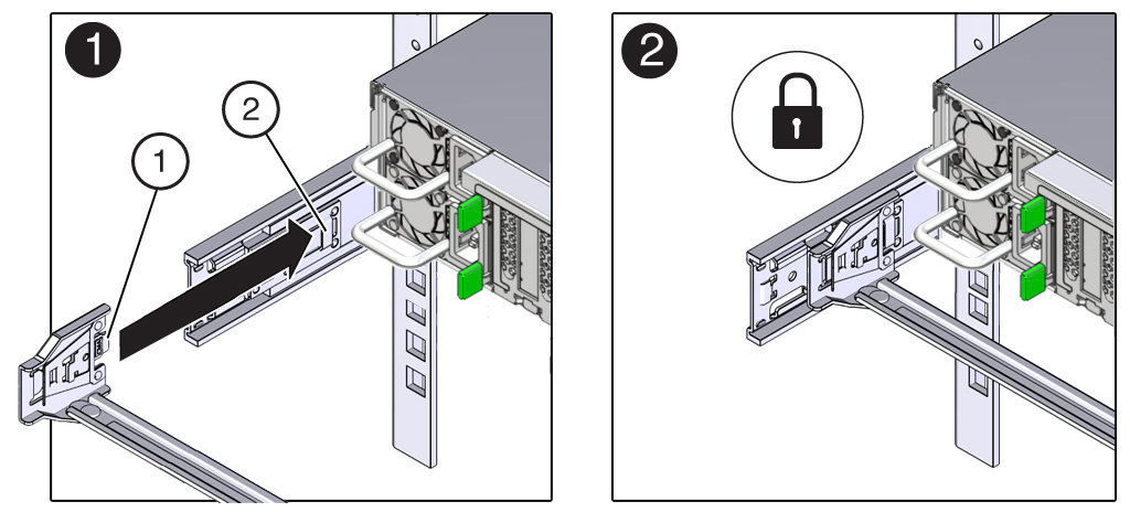
Description of the illustration a2498_new_frt_slide_bar_connx72.png
Call Out Description 1
Connector A tab
2
Left slide-rail front slot
-
Insert CMA connector A into the front slot on the left slide-rail
until it locks into place with an audible click [1 and 2].
-
To install CMA connector B into the right slide-rail:
-
Insert CMA connector B into the front slot on the right slide-rail
until it locks into place with an audible click [1 and 2].
The connector B tab (callout 1) goes into the slide-rail front slot (callout 2).
-
Gently tug on the right side of the front slide bar to verify that
connector B is properly seated.
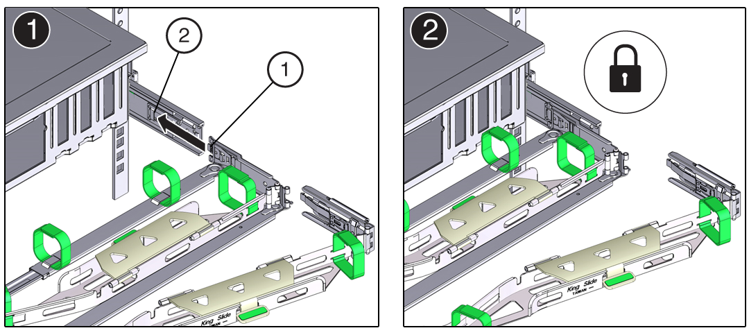
Description of the illustration a2502_cma_frt_side_bar_lt_installx72.png
Call Out Description 1
Connector B tab
2
Right slide-rail front slot
-
Insert CMA connector B into the front slot on the right slide-rail
until it locks into place with an audible click [1 and 2].
-
To install CMA connector C into the right slide-rail:
-
Align connector C with the slide-rail so that the locking spring
(callout 1) is positioned inside (server side) of the right
slide-rail [1].
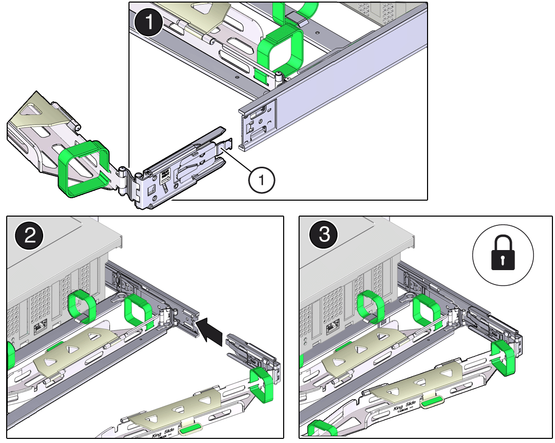
Description of the illustration mm-10236_rt_slide_rear_conn.pngCall Out Description 1
Connector C locking spring
- Insert connector C into the right slide-rail until it locks into place with an audible click [2 and 3].
- Gently tug on the right side of the CMA back slide bar to verify that connector C is properly seated.
-
Align connector C with the slide-rail so that the locking spring
(callout 1) is positioned inside (server side) of the right
slide-rail [1].
-
To prepare CMA connector D for installation, remove the tape that secures
the slide-rail latching bracket to connector D, and ensure that the latching
bracket is properly aligned with connector D [1 and 2].
Note:
The CMA is shipped with the slide-rail latching bracket taped to connector D. You must remove the tape before you install this connector.
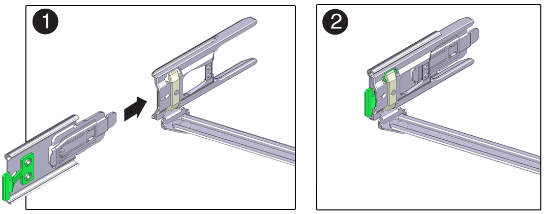
Description of the illustration a2489_lft_latch_bracket_2_panels.jpg
-
To install CMA connector D into the left slide-rail:
-
While holding the slide-rail latching bracket in place, insert
connector D and its associated slide-rail latching bracket into the
left slide-rail until connector D locks into place with an audible
click [1 and 2].
Note:
When inserting connector D into the slide-rail, the preferred and easier method is to install connector D and the latching bracket as one assembly into the slide-rail.
-
Gently tug on the left side of the CMA back slide bar to verify
that connector D is properly seated.
Note:
The slide-rail latching bracket has a green release tab. Use the tab to release and remove the latching bracket so that you can remove connector D.
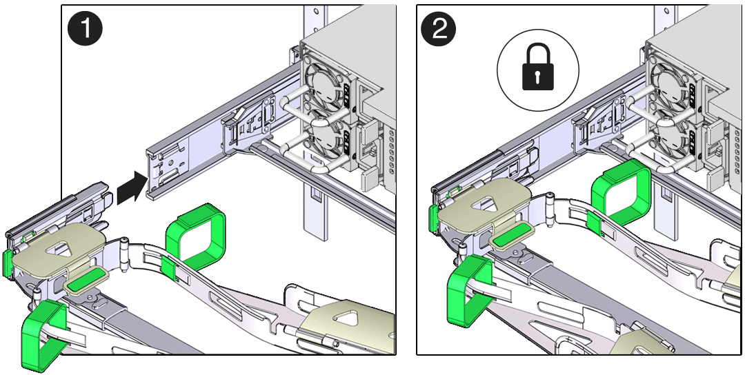
Description of the illustration mm-10239_cma_frt_side_bar_lt_install.png
-
While holding the slide-rail latching bracket in place, insert
connector D and its associated slide-rail latching bracket into the
left slide-rail until connector D locks into place with an audible
click [1 and 2].
- Gently tug on the four CMA connection points to ensure that the CMA connectors are fully seated before you allow the CMA to hang by its own weight.
-
To verify that the slide-rails and the CMA are operating properly before
routing cables through the CMA:
-
Ensure that the rack anti-tilt bar is extended to prevent the rack
from tipping forward when the server is extended.
Caution:
To reduce the risk of personal injury, stabilize the rack cabinet and extend the anti-tilt bar before extending the server from the rack.
For instructions to stabilize the rack, see Stabilize the Rack.
- Slowly pull the server out of the rack until the slide-rails reach their stops.
- Inspect the attached cables for any binding or kinks.
- Verify that the CMA extends fully with the slide-rails.
-
Ensure that the rack anti-tilt bar is extended to prevent the rack
from tipping forward when the server is extended.
-
To return the server to the rack:
- Simultaneously pull and hold the two green release tabs (one on each side of the server) toward the front of the server while you push the server into the rack. As you push the server into the rack, verify that the CMA retracts without binding.
- To pull the green release tabs, place your finger in the center of each tab, not on the end, and apply pressure as you pull the tab toward the front of the server.
-
Continue pushing the server into the rack until the slide-rail
locks (on the front of the server) engage the slide-rail
assemblies.
You hear a click when the server is in the normal rack position.
- Retract the rack anti-tilt mechanism back to its normal position.
- Connect cables to the server, as required.
-
Open the CMA cable covers, route the server cables through the CMA cable
troughs (in the order specified in the following steps), close the cable
covers, and secure the cables with the six Velcro straps.
- First through the front-most cable trough.
- Then through the small cable trough.
-
Then through the back-most cable trough.
Caution:
When securing the cables with the Velcro straps located on the front slide bar, ensure that the Velcro straps do not wrap around the bottom of the slide bar. Otherwise, expansion and contraction of the slide bar might be hindered when the server is extended from the rack and returned to the rack.
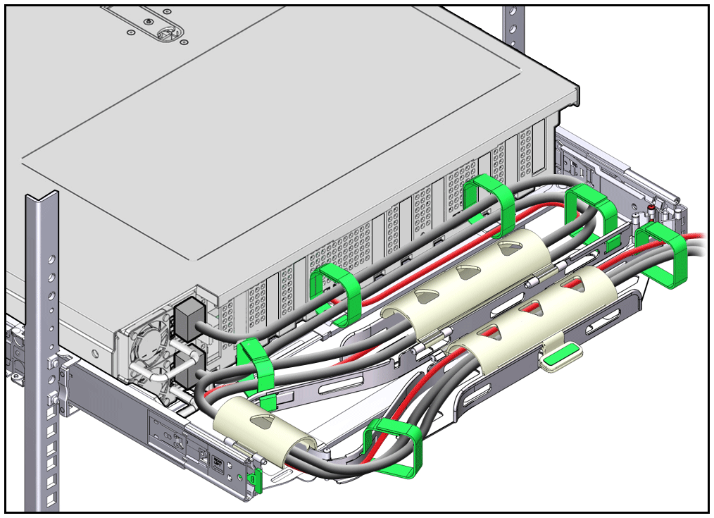
Description of the illustration mm-10240_2u_cabls_installed.png
-
Ensure that the secured cables do not extend above the top or below the
bottom of the server to which they are attached.
Otherwise, the cables might snag on other equipment installed in the rack when the server is extended from the rack or returned to the rack.
-
If necessary, bundle the cables with additional Velcro straps to ensure
that they stay clear of other equipment.
Note:
If you need to install additional Velcro straps, wrap the straps around the cables only, not around any of the CMA components. Otherwise, expansion and contraction of the CMA slide bars might be hindered when the server is extended from the rack and returned to the rack.
Parent topic: Returning Oracle Database Appliance to Operation
Powering On Oracle Database Appliance
- If your system includes a storage shelf, perform the following actions:
- If you powered off and disconnected the power cords from a storage shelf (and
storage expansion shelf if one is present), reconnect the power cords
now.The disks begin to initialize and the power supply LEDs light green. This can take several minutes.
Note:
Do not power on server nodes until the disks on the storage shelf and storage expansion shelf have initialized.
- If you powered off and disconnected the power cords from a storage shelf (and
storage expansion shelf if one is present), reconnect the power cords
now.
- If you powered off a server, performing the following actions:
- Reconnect any unplugged power cords.
As soon as the power cords are connected, Standby power is applied. In Standby power mode:
-
The System OK LED on the server front panel blinks slowly.
-
The SP OK LED indicator is steady on.
-
The AC power supply LED indicator lights are steady on.
Depending on the firmware configuration, the system might boot. If it does not boot, perform the following procedure.
-
- Power on the server to Main power mode by performing one of the following
actions:
-
Press the On/Standby button on the front bezel.
-
Log in to the Oracle ILOM web interface, click Host Management → Power Control, and select Power On from the Select Action list.
-
Log in to the Oracle ILOM command-line interface (CLI), and type the following command at the Oracle ILOM prompt:
->start /SystemWhen the server is powered on to Main power mode and the power-on self-test (POST) code checkpoint tests are complete, the green System OK LED status indicator on the front panel of the server lights and remains lit.
-
- Reconnect any unplugged power cords.
Parent topic: Returning Oracle Database Appliance to Operation
