2 Preparing Oracle Database Appliance for Service
How to prepare the Oracle Database Appliance for servicing.
Servicing System Components
These sections describe the serviceable components of the server.
- Illustrated Parts Breakdown
Identify major components of Oracle Database Appliance X10 server. - Customer-Replaceable Units
- Field-Replaceable Units
Parent topic: Preparing Oracle Database Appliance for Service
Illustrated Parts Breakdown
Identify major components of Oracle Database Appliance X10 server.
The following figure identifies Oracle Dababase Appliance X10 server major components.
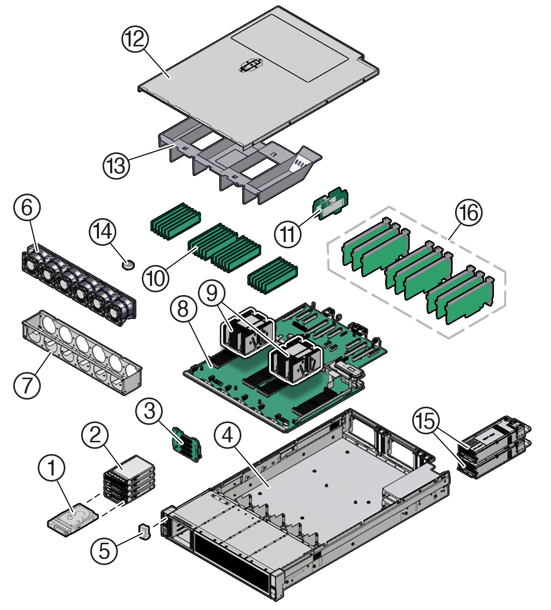
Description of the illustration mm-10168_oda-x10-illustrated-parts.png
| Callout | Description |
|---|---|
|
1 |
2.5-inch NVMe SSD (up to two supported with the Oracle Database Appliance X10-S, or up to four with the Oracle Database Appliance X10-L) |
|
2 |
Storage drive bay cage |
|
3 |
4-Drive backplane |
|
4 |
System chassis |
|
5 |
Front LED indicator module |
|
6 |
Six fan modules (FM0-5) |
|
7 |
Fan tray |
|
8 |
Motherboard assembly |
|
9 |
Processors (P0, P1) and heatsinks (Single-processor systems contain only a single processor in socket P0; socket P1 contains a cap to protect processor socket pins.) |
|
10 |
24 DIMMs (Twelve DIMMs are supported in single-processor systems and the DIMMs must be installed in P0 DIMM sockets.) |
|
11 |
Internal M.2 SSD memory with two internal M.2 Risers |
|
12 |
Top cover |
|
13 |
Air baffle |
|
14 |
System RTC battery |
|
15 |
Two power supplies (PS0, PS1) |
|
16 |
(Optional) Nine half-height half-length PCIe cards PCIe slots 1 through 4 are nonfunctional in single-processor systems. |
Parent topic: Servicing System Components
Customer-Replaceable Units
The following table lists the customer-replaceable units (CRUs) in the server, describes whether they can be serviced hot (with appliance power on) or cold (with appliance power off) and directs you to the replacement instructions.
| CRU (Service Level) | Description | Replacement Instructions |
|---|---|---|
|
Server battery (Cold service) |
Lithium coin-cell battery that powers the CMOS BIOS and real-time clock. |
|
|
Server DIMMs (Cold service) |
Add or replace memory modules in the system. |
|
|
Server storage drives (Hot service) |
Storage drive configurations can be comprised of both hard disk drives (HDDs), solid state disk drives (SSDs), or NVMe drives. |
|
|
Server internal M.2 flash SSDs (Cold service) |
Supports up to two internal M.2 flash SSDs. |
|
|
Server fan modules (Hot service) |
Four fan modules for cooling the server components. |
|
|
Server PCIe cards (Cold service) |
Optional add-on cards that can expand the functionality of the server. |
|
|
Server power supply units (Hot service) |
Two fully redundant AC-powered power supplies. |
|
|
Storage Shelf components (Hot service) |
Storage shelf SSDs, power supplies and IO modules. |
Oracle Database Appliance X10-HA Storage Shelf Hot Pluggable Components |
Field-Replaceable Units
The following table lists the field-replaceable units (FRUs) in the server and directs you to the replacement instructions.
Note:
Only authorized Oracle Service personnel can service FRU components.
| FRU (Service Level) | Description | Replacement Instructions |
|---|---|---|
|
Processor and heatsink (Cold service) |
Processor that carries out the instructions of the system. |
|
|
Fan tray (Cold service) |
Houses the fan modules. |
|
|
Disk backplane (Cold service) |
Provides power and communications connectors for storage drives. |
|
|
Front LED indicator module (Cold service) |
Contains the push-button circuitry and LEDs that are displayed on the front panel. |
|
|
PCIe slot Flyover cable (Cold service) |
Supports PCIe slots 6 and 7 in the system. |
|
|
Motherboard assembly (Cold service) |
Provides connectors for the DIMMs, processors, PCIe risers, and other components. |
Parent topic: Servicing System Components
Safety Precautions
For your protection, observe the following safety precautions when setting up your equipment:
-
Follow all standard cautions, warnings, and instructions marked on the equipment and described in the Oracle Server Safety and Compliance Guide and Important Safety Information for Oracle's Hardware Systems.
-
Ensure that the voltage and frequency of your power source match the voltage and frequency that appear on the equipment electrical rating label.
-
Follow the electrostatic discharge safety practices as described in Electrostatic Discharge Safety.
-
Disconnect both power supply cords (if necessary) before servicing components.
Note:
Power cords must be disconnected when servicing components that require cold service.
Parent topic: Preparing Oracle Database Appliance for Service
Safety Symbols
The following symbols might appear in this document. Note their meanings.
Caution:
Risk of personal injury or equipment damage. To avoid personal injury or equipment damage, follow the instructions.Caution:
Hot surface. Avoid contact. Surfaces are hot and might cause personal injury if touched.Caution:
Hazardous voltages are present. To reduce the risk of electric shock and danger to personal health, follow the instructions.Parent topic: Preparing Oracle Database Appliance for Service
Electrostatic Discharge Safety
Devices that are sensitive to electrostatic discharge (ESD), such as the motherboard, PCIe cards, drives, processors, and memory DIMMs require special handling.
Caution:
The boards and drives contain electronic components that are extremely sensitive to static electricity. Ordinary amounts of static electricity from clothing or the work environment can destroy components. Do not touch the components along their connector edges.Do the following when handling ESD-sensitive components:
-
Use an antistatic wrist strap.
Wear an antistatic wrist strap when handling components such as drive assemblies, boards, or cards. When servicing or removing server components, disconnect the power cords from the server. Attach an antistatic strap to your wrist and to a metal area on the chassis. Following this practice equalizes the electrical potentials between you and the server.
Note:
An antistatic wrist strap is not included in the Accessory Kit for the server. However, antistatic wrist straps are included with optional components. -
Use an antistatic mat.
Place ESD-sensitive components such as the motherboard, DIMMS (memory modules), and other printed circuit board (PCB) cards on an antistatic mat. The following items can be used as an antistatic mat:
-
Antistatic bag used to wrap an Oracle replacement part
-
Oracle ESD mat (orderable item)
-
Disposable ESD mat (shipped with some replacement parts or optional system components)
-
Parent topic: Preparing Oracle Database Appliance for Service
FRU Key Identity Properties (KIP) Automated Update
Oracle ILOM includes a key identity properties (KIP) auto-update feature that ensures product information that is used for service entitlement and warranty coverage is accurately maintained by the server at all times, including during hardware replacement activities.
The KIP includes the server product name, product part number (PPN), and product serial number (PSN). The KIP is stored in the FRUID (field-replaceable unit identifiers) container of the three server FRUs that are designated quorum members.
The quorum members include:
-
Disk backplane (DBP), designated as a primary quorum member.
-
Motherboard (MB), designated as a backup quorum member.
-
Power supply (PS), designated as a backup quorum member.
When a server FRU that contains the KIP is removed and a replacement component is installed, the KIP of the replacement component is programmed by Oracle ILOM to contain the same KIP as the other two components.
Note:
Only one of the quorum members can be replaced at a time. Automated updates can be completed only when two of the three quorum members contain matching key identity properties.Parent topic: Preparing Oracle Database Appliance for Service
Required Service Tools
The server can be serviced with the following tools:
-
Antistatic wrist strap
-
Antistatic mat(s)
-
No. 2 Phillips screwdriver
-
Torx (6 lobe) T10, T15, T20, and T25 drivers
-
Torque driver 12 in-lbf with T20 Torx bit (processor and heatsink installation)
-
Small flat blade screwdriver (motherboard light pipe removal)
Parent topic: Preparing Oracle Database Appliance for Service
Preparing the Server for Component Replacement
Note:
When you are replace the storage drives or power supplies, not all of the procedures in this section are necessary. For more information, see the replacement procedures for those components.Before you can remove and install components that are inside the server, you must perform the procedures in some or all of the following sections.
- Powering Down the Server
- Disconnect Cables From the Server
- Stabilize the Rack
- Extend the Server to the Maintenance Position
- Remove the Cable Management Arm
- Remove the Server From the Rack
- Take Antistatic Measures
- Remove the Server Top Cover
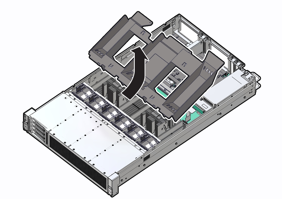
- Remove the Air Baffle
Parent topic: Preparing Oracle Database Appliance for Service
Powering Down the Server
Gracefully shut down the server host to prevent data from being corrupted. Performing a graceful shutdown ensures that the system is ready for restart. If the server is not responding, or you must shut down the server quickly, perform an immediate shutdown.
Note:
Some server components, such as storage drives, power supplies, fan modules, and M.2 flash SSDs are hot-pluggable. Components that are hot-pluggable do not require the server to be powered down when performing service procedures.Determine how you want to power down the server by reviewing the following options.
- Power Down the Server Gracefully Using Oracle ILOM CLI
- Power Down the Server Gracefully Using Oracle ILOM Web Interface
- Power Down the Server Gracefully Using the On/Standby Button
- Power Down the Server for Immediate Shutdown Using Oracle ILOM CLI
- Power Down the Server for Immediate Shutdown Using Oracle ILOM Web Interface
- Power Down the Server for Immediate Shutdown Using the On/Standby Button
Parent topic: Preparing the Server for Component Replacement
Power Down the Server Gracefully Using Oracle ILOM CLI
Performing a graceful shutdown ensures that all of your data is saved and the system is ready for restart.
Parent topic: Powering Down the Server
Power Down the Server Gracefully Using Oracle ILOM Web Interface
Performing a graceful shutdown ensures that all of your data is saved and the system is ready for restart.
Parent topic: Powering Down the Server
Power Down the Server Gracefully Using the On/Standby Button
Power down the server using the On/Standby button. Performing a graceful shutdown ensures that all of your data is saved and the system is ready for restart.
Parent topic: Powering Down the Server
Power Down the Server for Immediate Shutdown Using Oracle ILOM CLI
Caution:
An immediate power-off might corrupt system data, therefore, use this procedure to power down the server only after attempting the graceful power down procedure.Parent topic: Powering Down the Server
Power Down the Server for Immediate Shutdown Using Oracle ILOM Web Interface
Caution:
An immediate power-off might corrupt system data, therefore, use this procedure to power down the server only after attempting the graceful power down procedure.Parent topic: Powering Down the Server
Power Down the Server for Immediate Shutdown Using the On/Standby Button
Caution:
An immediate power-off might corrupt system data, therefore, use this procedure to power down the server only after attempting the graceful power down procedure.Parent topic: Powering Down the Server
Disconnect Cables From the Server
Caution:
The system supplies Standby power to the circuit boards even when the system is powered off.Parent topic: Preparing the Server for Component Replacement
Stabilize the Rack
Caution:
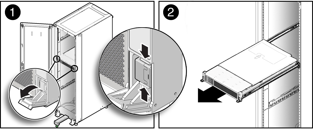
To reduce the risk of personal injury, stabilize the rack cabinet, and extend the anti-tilt bar before you install the server.
Refer to your rack documentation for detailed instructions for the following steps.
Related Rack Documentation
Parent topic: Preparing the Server for Component Replacement
Extend the Server to the Maintenance Position
The following components can be serviced with the server in the maintenance position:
-
Fan modules
-
Storage drives
-
DDR5 DIMMs
-
Processors
-
M.2 Flash drives and risers
-
System battery
-
Motherboard
-
PCIe cards and cables
-
Disk backplane
-
Front indicator module
If the server is installed in a rack with extendable slide-rails, use this procedure to extend the server to the maintenance position.
Parent topic: Preparing the Server for Component Replacement
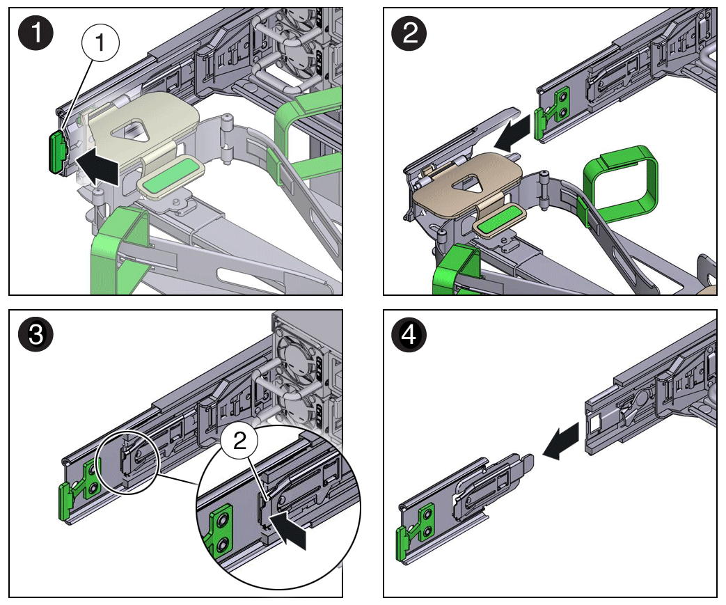
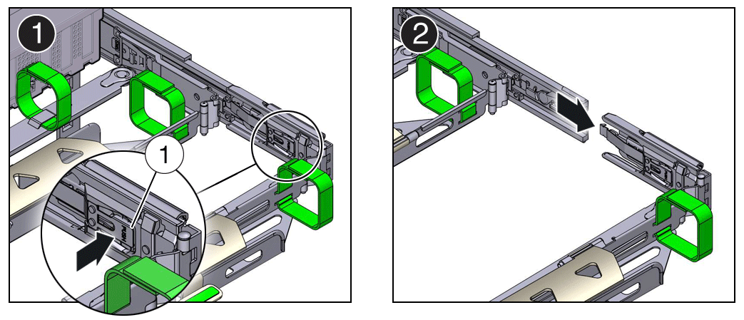
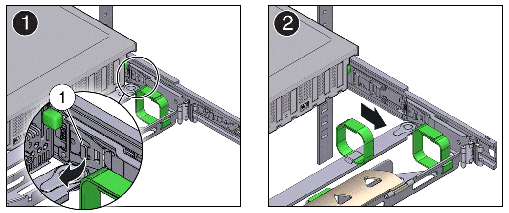
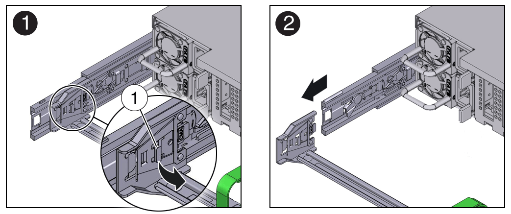
Remove the Cable Management Arm
Follow this procedure to remove the cable management arm (CMA). You might need to remove the CMA to service power supplies or cables connected to the back of the system.
Before you begin this procedure, refer to the illustration provided in the procedure Install the Cable Management Arm (Optional) to identify CMA connectors A, B, C, and D. Disconnect the CMA connectors in the reverse order in which you installed them, that is, disconnect connector D first, followed by C, B, and A.
Throughout this procedure, after you disconnect any of the CMA four connectors, do not allow the CMA to hang under its own weight.
Note:
References to “left” or “right” in this procedure assume that you are facing the back of the equipment rack.
Parent topic: Preparing the Server for Component Replacement
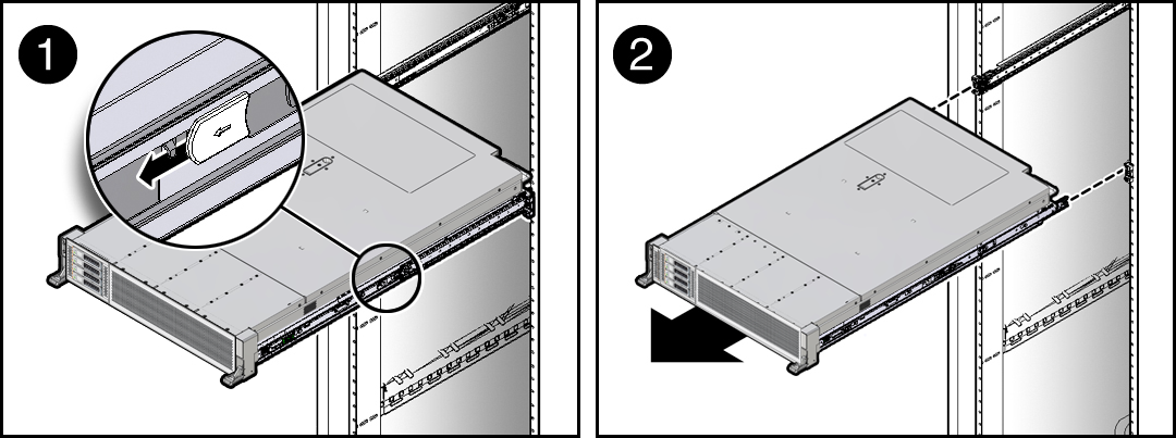
Remove the Server From the Rack
This section describes how to remove the server from the rack. For most service actions you won't need to do this.
Caution:
The server weighs approximately 76 lbs (34 kg). A mechanical lift or two people are required to remove the server from the rack and carry the chassis.Always load equipment into a rack from the bottom up so that the rack does not become top-heavy and tip over. Extend the rack anti-tilt bar to prevent the rack from tipping during equipment installation.
Parent topic: Preparing the Server for Component Replacement
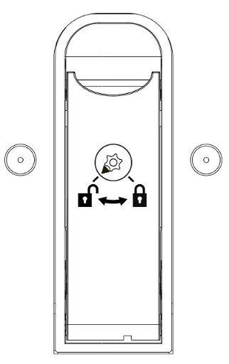
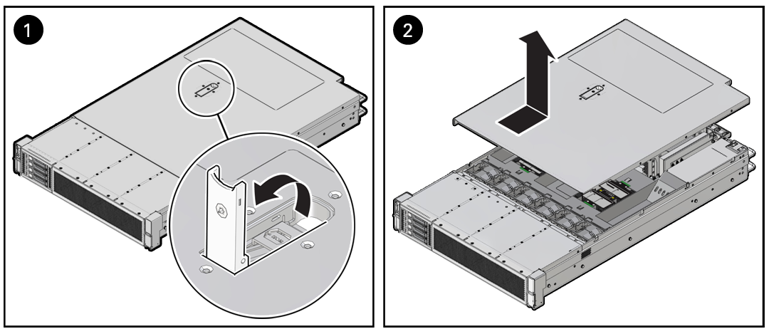
Remove the Server Top Cover
Remove the top cover to service components inside the server.
Parent topic: Preparing the Server for Component Replacement
