4 Servicing CRUs That Require System Power Off

Perform tasks for servicing customer-replaceable units (CRUs) for the Oracle Database Appliance that require you to power off system components.

Note:

The servicing of hot-plug components such as the HDDs, SDDs, power supplies, and fans is described in Servicing CRUs That Do Not Require System Power Off.

Servicing Internal M.2 Flash SSDs (CRU)

Perform the task of servicing M.2 flash solid-state drives (SSDs).

M.2 flash SSDs are replaceable components that require you to power off the server before servicing.

Caution:

These procedures require that you handle components that are sensitive to electrostatic discharge. This sensitivity can cause the component to fail. To avoid damage, ensure that you follow antistatic practices, as described in Electrostatic Discharge Safety.

Caution:

Ensure that all power is removed from the server before removing or installing M.2 SSDs or flash risers. You must disconnect all power cables from the system before performing these procedures.

Identify and Remove an M.2 Flash SSD

The server can contain up to two flash riser boards (SSDR0, SSDR1). Each flash riser board can contain one M.2 flash SSD.

  1. If you have a failed M.2 SSD, determine which SSD has failed.
    1. Log into Oracle ILOM CLI and run the show command to list available storage controllers.

      For example:

      -> show /System/Storage/Controllers/
                     /System/Storage/Controllers
                     Targets:
                     Controller_0
                     Controller_1
                     Controller_2
                     Controller_3

      Note that the M.2 SSDs are normally the last two listed in the output.

    2. Then list the status of a specific M.2 SSD.

      For example:

      -> show /System/Storage/Controllers/Controller_2
          Targets:
          Properties:
              health = OK
              health_details = -
              serial_number = 23023E3387B3
              location = SSDR0/SSD0/NVME (SSD Riser 0 NVME SSD 0)
              type = NVMe
              manufacturer = MICRON
              model = Micron_7450_MTFDKBA480TFR
              wwns = Not Available
              number_of_ports = Not Available

      For a failed SSD, note the location to ensure you replace the correct SSD. The location includes the specific flash riser (such as SSDR0 or SSDR1) on which the SSD resides. The labels for the flash risers are on the motherboard near the rear of the system (look for SSDR 0 and SSDR 1).

      Note:

      Additionally, failed components are listed under /System/Open_Problems in Oracle ILOM.
  2. Prepare the server for service.
    1. Power off the server.
    2. Disconnect the power cords from the power supplies.
    3. Extend the server into maintenance position.
    4. Attach an antistatic wrist strap to your wrist, and then to a metal area on the chassis.
    5. Remove the server top cover.
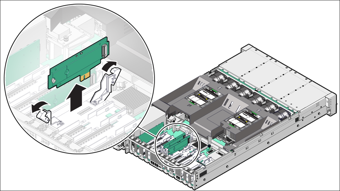
  3. To remove the flash riser board, do the following:
    1. Rotate both riser board securing levers outward as far as they go.

      Caution:

      The levers are not ejectors. Attempting to force the levers open too far can damage them.
    2. Carefully lift the riser board straight up to remove it from its motherboard socket.
  4. Place the riser board on an antistatic mat.
  5. Remove the M.2 flash SSD from the riser board.
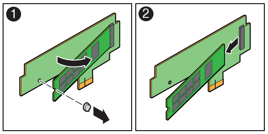
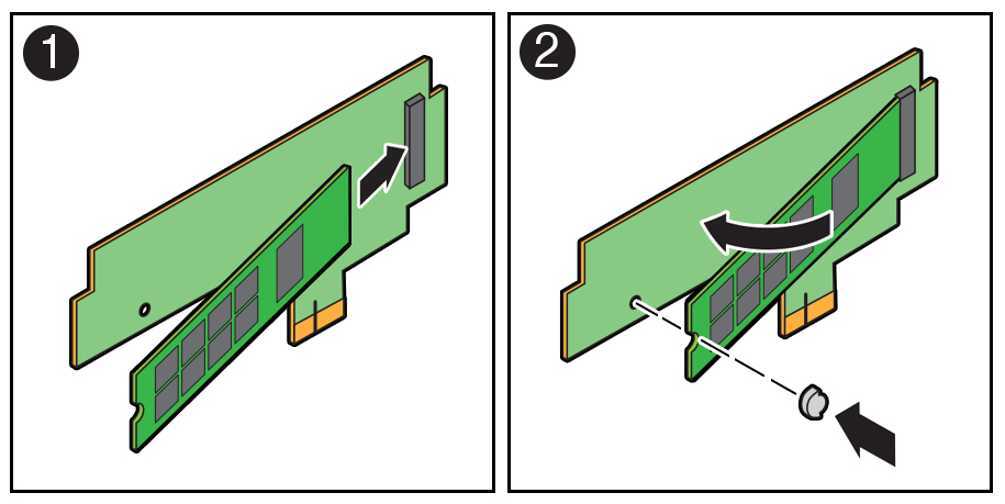
    1. Using your fingers, push the part of the plastic retainer clip that protrudes through the hole on the back side of the riser board through the hole to the front side of the riser board [1]. Then gently lift up on the end of the M.2 flash SSD approximately one-half to one inch and remove the plastic retainer clip from the end of the M.2 flash SSD.
    2. Remove the M.2 flash SSD from its connector socket on the riser board socket [2].
    3. Place the M.2 flash SSD on an antistatic mat.

Install an M.2 Flash SSD

The flash riser board should have already been removed as described in Identify and Remove an M.2 Flash SSD.

  1. Unpack the replacement M.2 flash SSD and place it on an antistatic mat.
  2. Install the M.2 flash SSD onto the riser board.
    1. At an approximate 45 degree angle, insert the M.2 flash SSD into its connector socket on the riser board socket [1].
    2. With the M.2 flash SSD at an approximate 45 degree angle to the riser board, insert the plastic retainer clip into the notched end of the M.2 flash SSD and then push down on the end of the M.2 flash SSD until the retainer clip snaps into place in the hole on the riser board [2].

      You hear an audible click when the M.2 flash SSD is secured to the flash riser board.

  3. Install the flash riser board.
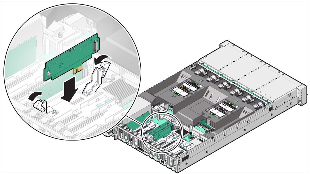
    1. Ensure that the riser board securing levers on the motherboard are in the open position.
    2. Align the notch in the replacement riser board with the connector key in the connector socket.

      The notch ensures that the riser board is oriented correctly.

    3. Push the riser board into its connector socket on the motherboard until the riser board is securely seated in the socket.

      Caution:

      If the riser board does not easily seat into the connector socket, verify that the notch in the riser board is aligned with the connector key in the connector socket. If the notch is not aligned, damage to the riser board might occur.
      Description of mm-10518_flash-riser-install.png follows
      Description of the illustration mm-10518_flash-riser-install.png
    4. Rotate the riser board securing levers inward until the riser board is secured in place.
  4. Return the server to operation.
    1. Install the server top cover.
    2. Return the server to the normal rack position.
    3. Reconnect the power cords to the server power supplies, and power on the server.
    4. Verify that the System OK LED indicator is lit.

Remove a Flash Riser Board

Follow the instructions in this section if you need to replace a flash riser board.

The server includes two flash riser boards (SSDR0, SSDR1). Each flash riser board can contain one M.2 flash SSD.

  1. Prepare the server for service.
    1. Power off the server.
    2. Disconnect the power cords from the power supplies.
    3. Extend the server into maintenance position.
    4. Attach an antistatic wrist strap to your wrist, and then to a metal area on the chassis.
    5. Remove the server top cover.
  2. To remove the flash riser board, do the following:
    1. Rotate both riser board securing levers outward as far as they go.

      Caution:

      The levers are not ejectors. Attempting to force the levers open too far can damage them.
    2. Carefully lift the riser board straight up to remove it from its motherboard socket.
  3. Place the riser board on an antistatic mat.
  4. Remove the M.2 flash SSD from the riser board.
    1. Using your fingers, push the part of the plastic retainer clip that protrudes through the hole on the back side of the riser board through the hole to the front side of the riser board [1]. Then gently lift up on the end of the M.2 flash SSD approximately one-half to one inch and remove the plastic retainer clip from the end of the M.2 flash SSD.
    2. Remove the M.2 flash SSD from its connector socket on the riser board socket [2].
    3. Place the M.2 flash SSD on an antistatic mat.

Install a Flash Riser Board

The system motherboard provides two slots (labeled SSDR 0 and SSDR 1) for flash riser boards. When installing flash riser boards, install the first riser board into slot SSDR 0 and the second into SSDR 1.

  1. Unpack the replacement flash riser board and place it on an antistatic mat.
  2. Install the M.2 flash SSD onto the riser board.
    1. At an approximate 45 degree angle, insert the M.2 flash SSD into its connector socket on the riser board socket [1].
    2. With the M.2 flash SSD at an approximate 45 degree angle to the riser board, insert the plastic retainer clip into the notched end of the M.2 flash SSD and then push down on the end of the M.2 flash SSD until the retainer clip snaps into place in the hole on the riser board [2].

      You hear an audible click when the M.2 flash SSD is secured to the flash riser board.

  3. Install the flash riser board.
    1. Ensure that the riser board securing levers on the motherboard are in the open position.
    2. Align the notch in the replacement riser board with the connector key in the connector socket.

      The notch ensures that the riser board is oriented correctly.

    3. Push the riser board into its connector socket on the motherboard until the riser board is securely seated in the socket.

      Caution:

      If the riser board does not easily seat into the connector socket, verify that the notch in the riser board is aligned with the connector key in the connector socket. If the notch is not aligned, damage to the riser board might occur.
      Description of mm-10518_flash-riser-install.png follows
      Description of the illustration mm-10518_flash-riser-install.png
    4. Rotate the riser board securing levers inward until the riser board is secured in place.
  4. Return the server to operation.
    1. Install the server top cover.
    2. Return the server to the normal rack position.
    3. Reconnect the power cords to the server power supplies, and power on the server.
    4. Verify that the System OK LED indicator is lit.

Servicing DIMMs (CRU)

Perform this task to service dual in-line memory modules (DIMMs).

DIMMs are replaceable components that require you to power off the server before servicing.

Caution:

These procedures require that you handle components that are sensitive to electrostatic discharge. This sensitivity can cause the components to fail. To avoid damage, ensure that you follow antistatic practices as described in Electrostatic Discharge Safety.

Caution:

Ensure that all power is removed from the server before removing or installing DIMMs, or damage to the DIMMs might occur. You must disconnect all power cables from the system before performing these procedures.

The topics and procedures in this section provide information to assist you when replacing a DIMM or upgrading DIMMs.

DIMM and Processor Physical Layout

The physical layout of the DIMMs and processor(s) is shown in the following figure. When viewing the server from the front, processor 0 (P0) is on the left.
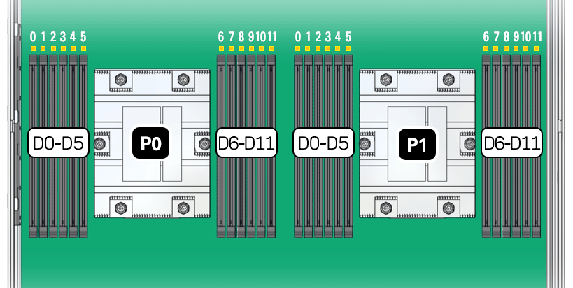
Figure showing the AMD DIMM and processor layout.

Each processor, P0 and P1, has twelve DIMM slots (D0-D11), six on each processor side. Each DIMM slot supports a single memory channel, for total of twelve DDR5 memory channels per processor (0-11).

Table 4-1 Memory Channels and DIMM Slots for P0 and P1

Memory Channel DIMM Slot

0

D3

1

D1

2

D0

3

D5

4

D4

5

D2

6

D8

7

D10

8

D11

9

D6

10

D7

11

D9

Note:

In single-processor systems, the DIMM slots associated with processor 1 (P1) are nonfunctional and should not be populated with DIMMs.

DIMM Population Scenarios

There are two scenarios in which you are required to populate DIMMs:

  • A DIMM fails and needs to be replaced.

    In this scenario, you can use the Fault Remind button to determine the failed DIMM, and then remove the failed DIMM and replace it. To ensure that system performance is maintained, you must replace the failed DIMM with a DIMM of the same size (in gigabytes) and type (quad-rank or dual-rank). In this scenario, do not change the DIMM configuration.

  • You purchased new DIMMs and want to use them to upgrade the server memory.

    In this scenario, you must adhere to the DIMM population rules and follow the recommended DIMM population order for optimal system performance.

DIMM Population Rules

The population rules for adding DIMMs to the server are as follows:

  • The server supports:

    • Up to 24 DDR5 DIMMs, 12 per processor socket.

    • 64 GB dual-rank (DR) Registered DIMMs (RDIMMS).

    • A maximum supported memory speed of 4800 MT/s.

      However, the maximum attainable memory speed could be limited by the maximum speed supported by a specific processor or DIMM. All memory installed in the system operates at the same speed, or frequency.

  • Populate all 12 memory DIMMs per processor to achive the highest system performance. If populating 12 memory DIMMs per processor is not feasible, populate each processor with 1, 2, 4, 6, 8, or 10 DIMMs.
  • Populate each memory channel with the same capacity and number of banks.

  • Populate processor 0 (P0) and processor 1 (P1) using the same DIMM configuration. Failure to do so will result in lower system performance.

  • The server operates properly with a minimum of one DIMM installed per processor. Install one DIMM in slot D5 on each processor.

  • Each DIMM is shipped with a label identifying its rank classification (dual or quad). The following identifies the label corresponding to the supported DIMM rank classification: Dual-rank RDIMM 2Rx4

  • Do not mix DIMM types in a server. Load-Reduced (LRDIMMs) are not supported.

  • The server does not support lockstep memory mode, which is also known as double device data correction, or Extended ECC.

  • Populate the DIMM slots in the order described in the following sections, which provide an example of how to populate the DIMM slots to achieve optimal system performance.

  • DIMM fillers must be installed in any unpopulated DIMM slots. This is a requirement for proper server cooling.

Populating DIMMs for Optimal System Performance

Supported per-processor configurations for optimal performance are listed below. DIMM slots must be populated identically for both processors. For an illustration, see DIMM and Processor Physical Layout.

  • Populate DIMMs of the same size in multiples of four (for a single processor system) or eight (for a dual processor system).

  • The DIMM population for each processor (P0 and P1) must be identical.

  • The DIMM population for each server node must be identical.

ODA X10-S DIMM Populations (Single Processor) ODA X10-L DIMM Populations (Dual Processor) ODA X10-HA DIMM Populations (Dual Processor, Dual Server Node)
  • Four DIMM configuration (factory default). DIMM slots D3, D5, D6 and D8 are populated

  • Eight DIMM configuration. DIMM slots D1, D3, D4, D5, D6, D7, D8 and D10 are populated

  • Twelve DIMM configuration. Slots D0 through D11 are populated

  • Eight DIMM configuration (factory default). DIMM slots D3, D5, D6 and D8 are populated for each processor

  • Sixteen DIMM configuration. DIMM slots D1, D3, D4, D5, D6, D7, D8 and D10 are populated for each processor

  • Twenty-four DIMM configuration. DIMM slots D0 through D11 are populated for each processor

Using the Server Fault Remind Button

When you press the server Fault Remind button [1], an LED located next to the Fault Remind button lights green which indicates that there is sufficient voltage present in the fault remind circuit to light any fault LEDs that were lit due to a component failure. If this LED does not light when you press the Fault Remind button, it is likely that the capacitor powering the fault remind circuit has lost its charge. This can happen if the Fault Remind button is pressed for several minutes with fault LEDs lit, or if power is removed from the server for more than 15 minutes.

The following figure shows the location of the Fault Remind button on the motherboard.
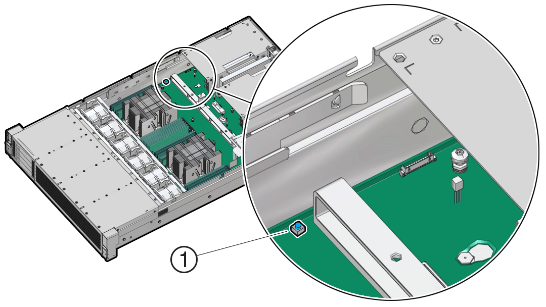
Figure showing the location of the 4-Drive Fault Remind Button.

Identify and Remove a DIMM

  1. Prepare the server for service.
    1. Power off the server.
    2. Disconnect the power cords from the power supplies.
    3. Extend the server into the maintenance position.
    4. Attach an antistatic wrist strap to your wrist and then to a metal area on the chassis.
    5. Remove the server top cover.
    6. Remove the air baffle.
  2. Identify and note the location of the failed DIMM by pressing the Fault Remind button on the motherboard.

    See Using the Server Fault Remind Button.

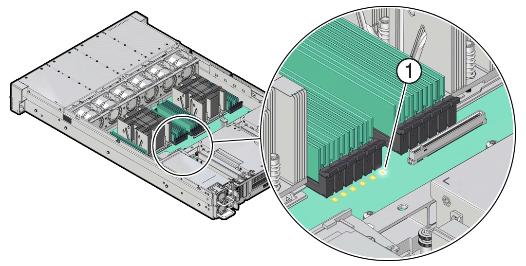
    Failed DIMMs are identified with a corresponding amber LED on the motherboard.

    • If the DIMM Fault LED is off, then the DIMM is operating properly.

    • If the DIMM Fault LED is on (amber), then the DIMM is failed and must be replaced [1].

    Description of mm-10528_dimm-fault-led-1.png follows
    Description of the illustration mm-10528_dimm-fault-led-1.png
  3. To remove the failed DIMM, do the following:
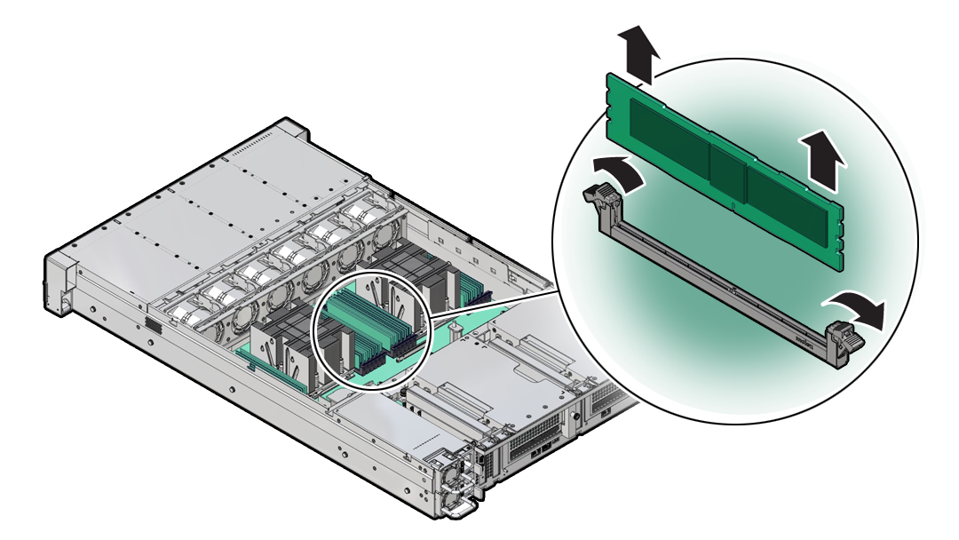
    1. Rotate both DIMM slot ejectors outward as far as they go.

      The DIMM is partially ejected from the slot.

    2. Carefully lift the DIMM straight up to remove it from the slot.
  4. Replace each failed DIMM with either another DIMM of the same rank size (quad-rank or dual-rank) or leave the slot empty.

    For DIMM replacement instructions, see Install a DIMM.

Install a DIMM

  1. Unpack the replacement DIMM and place it on an antistatic mat.
  2. Ensure that the replacement DIMM matches the size, type, and rank of the DIMM it is replacing.
  3. Install a DIMM.
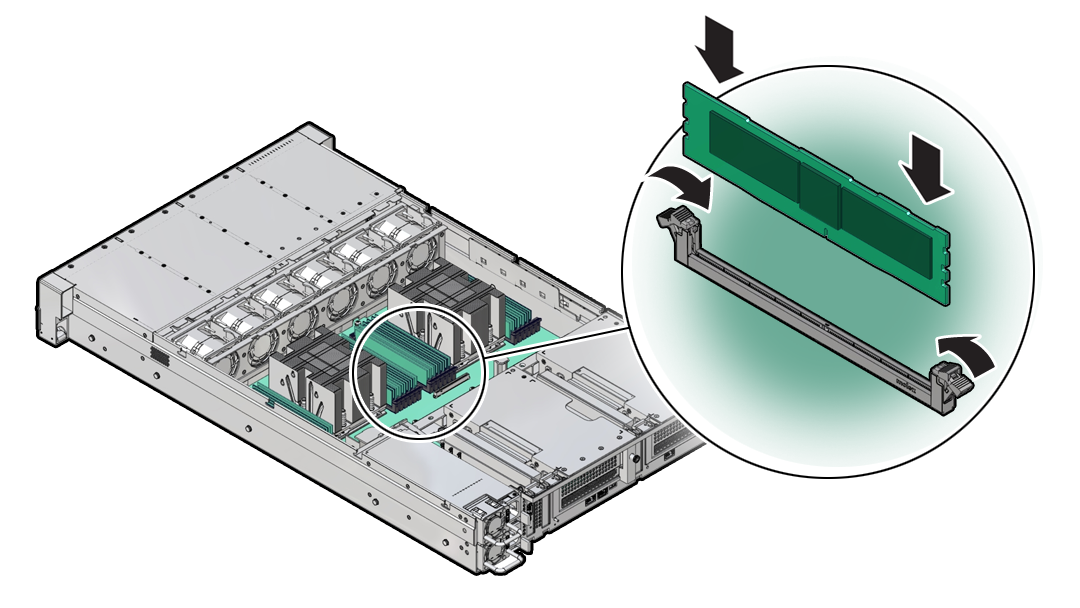
    1. Ensure that the ejector tabs are in the open position.
    2. Align the notch in the replacement DIMM with the connector key in the connector slot.

      The notch ensures that the DIMM is oriented correctly.

    3. Push the DIMM into the connector slot until the ejector tabs lock the DIMM in place.

      If the DIMM does not easily seat into the connector slot, verify that the notch in the DIMM is aligned with the connector key in the connector slot.

      Caution:

      If the notch is not aligned, damage to the DIMM might occur.
      Description of mm-10530_installing-dimm.png follows
      Description of the illustration mm-10530_installing-dimm.png
  4. Repeat Step 3 until all replacement DIMMs are installed.
  5. Return the server to operation.
    1. Install the server top cover.
    2. Return the server to the normal rack position.
    3. Reconnect the power cords to the server power supplies, and power on the server.
    4. Verify that the System OK LED indicator is lit.
  6. (Optional) Use Oracle ILOM to clear server DIMM faults.

    DIMM faults are automatically cleared after a new DIMM has been installed. If you need to manually clear DIMM faults, refer to Oracle ILOM Documentation.

    Note:

    If you want to move a failed DIMM to a new DIMM slot or re-seat a DIMM for troubleshooting, you must first manually clear the associated DIMM fault. Otherwise, the DIMM fault might follow the DIMM to the new slot location or reoccur in the current slot location, causing a false DIMM fault condition.

Servicing PCIe Cards (CRU)

Perform tasks to service PCIe cards in the system.

PCIe cards are replaceable components that require you to power off the server before servicing.

Note:

The Oracle Database Appliance does not support PCIe card Hot-Plug.

Caution:

These procedures require that you handle components that are sensitive to electrostatic discharge. This sensitivity can cause the components to fail. To avoid damage, ensure that you follow antistatic practices as described in Electrostatic Discharge Safety.

Caution:

Ensure that all power is removed from the server before removing or installing PCIe cards. You must disconnect all power cables from the system before performing these procedures.

PCIe Slot Locations

Depending on the number of processors installed, the server is designed to support up to 9 half height PCIe cards.

  • All card slots support Half Height, Half Length (HHHL) PCIe cards (Low profile short) at PCIe Gen4 or Gen5.
  • All PCIe card slots are 75W capable slots. All of the PCIe slots comply with the PCI Express 5.0 specification and can accommodate 75 Watt PCIe cards.
  • For the Oracle Database Appliance X10-S, a single processor system, PCIe card slots 1 through 4 are nonfunctional.
  • For the Oracle Database Appliance X10-S and X10-L, a special Oracle Retimer card is installed in PCIe slot 6 and is required for front panel NVMe storage drives to work. PCIe slot 7 is non-functional.

Adding Optional PCIe Cards (CRU)

Describes installation sequence for adding optional PCIe cards to an Oracle Database Appliance.

The Oracle Database Appliance X10 series systems support up to three optional public network cards (or three network cards per node if you have an X10-HA). The Oracle Database Appliance X10-L supports up to four Oracle Flash Accelerator 680 PCIe Cards.

  • If possible, order any optional PCIe cards when you initially buy the system and have the cards factory installed.

  • If you want to add or replace PCIe cards after your appliance has been delivered from the factory, the following rules apply:

    • You can install any of the supported PCIe cards listed in the table below.

    • You must install optional PCIe cards in the proper order and slots (refer to the table below).

    • If you want to replace an existing network card, you must first delete the network card and its network interface using the appliance oftware. Then replace the physical network card with the new one. When the appliance is restarted the new network card will be used. For specific instructions on software removal or configuration of a public network card, refer to the Deployment and User's Guide.

      Note:

      You cannot replace the factory installed public network card installed in PCIe slot 5. In addition, for the Oracle Database Appliance X10-HA, you cannot replace the factory installed cluster interconnect network card installed in PCIe slot 1.

The following table describes the supported PCIe cards and the order in which they can be installed in the system.

Description Oracle Database Appliance X10-S Oracle Database Appliance X10-L Oracle Database Appliance X10-HA (per node)

Supported PCIe cards

  • Oracle Dual Port 25 Gb Ethernet Adapter

  • Oracle Quad Port 10GBase-T Adapter

  • Oracle Dual Port 25 Gb Ethernet Adapter

  • Oracle Quad Port 10GBase-T Adapter

  • Oracle Flash Accelerator 680 PCIe Card

  • Oracle Dual Port 25 Gb Ethernet Adapter

  • Oracle Quad Port 10GBase-T Adapter

Installation order

Optional network cards:

  1. By default, the server comes with a public network card installed in PCIe slot 5.
  2. A second public network card can be installed in PCIe slot 9.
  3. A third public network card can be installed in PCIe slot 8.

Optional network cards:

  1. By default, the server comes with a public network card installed in PCIe slot 5.
  2. A second public network card must be installed in PCIe slot 4.
  3. A third public network card must be installed in PCIe slot 8.

Optional Oracle Flash Accelerator 680 PCIe Cards:

  1. The first Oracle Flash Accelerator card must be installed in PCIe slot 2.
  2. A second Oracle Flash Accelerator card must be installed in PCIe slot 3.
  3. A third Oracle Flash Accelerator card must be installed in PCIe slot 9.
  4. A fourth Oracle Flash Accelerator card must be installed in PCIe slot 1.

Optional network cards:

  1. By default, each server node comes with a public network card installed in PCIe slot 5.
  2. A second public network card can be installed in PCIe slot 4.
  3. A third public network card can be installed in PCIe slot 8.

Installation intructions:

Install a Half Height PCIe Card

Install a Half Height PCIe Card

Install a Half Height PCIe Card

Remove a Half Height PCIe Card

Before replacing or installing a PCIe card, refer to the card documentation for specific installation and cabling instructions.
  1. Prepare the server for service.
    1. Power off the server.
    2. Disconnect the power cords from the power supplies.
    3. Extend the server to the maintenance position.
    4. Attach an antistatic wrist strap.
    5. Remove the server top cover.
  2. Locate the PCIe card that you want to remove.

    Note:

    PCIe slots 1 through 4 are nonfunctional in single-processor systems.

  3. If necessary, record where the PCIe cards are installed.
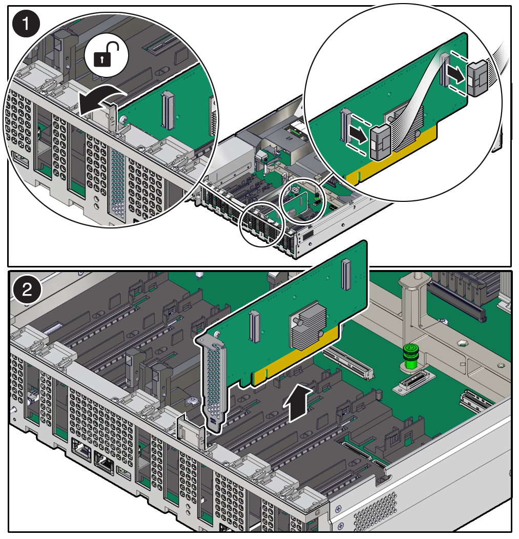
  4. Unplug all data cables from the PCIe card [1].

    Note the cable connections so that it's easier to properly reconnect the cables.

    If it is difficult to disconnect the cables from the PCIe card when the card is inserted into the PCIe slot, consider performing the procedure in Step 5 before completing this step.

  5. Rotate the PCIe card locking mechanism in to an upright position [1], and then lift up on the PCIe card to disengage it from the motherboard connectors [2].
  6. Place the PCIe card on an antistatic mat.

    Caution:

    If you are not immediately inserting a replacement PCIe card into the empty slot, insert a PCIe filler panel in the slot to reduce the possibility of radiated electromagnetic interference (EMI).

Install a Half Height PCIe Card

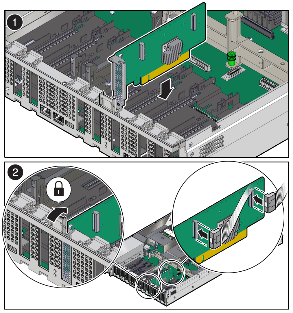
  1. Unpack the replacement PCIe card, and place it on an antistatic mat.
    Before replacing or installing a PCIe card, refer to the card documentation for specific installation and cabling instructions.
  2. Locate the proper PCIe slot for the card you are replacing.
    PCIe slots 1 through 4 are nonfunctional in single-processor systems.
  3. If necessary, remove the PCIe filler panel from the slot.
    Save this filler panel in case you need to remove the PCIe card from the system.
  4. Insert the PCIe card into the correct slot [1], and rotate the PCIe locking mechanism downward to secure the PCIe card in place [2].

    You hear an audible click when the PCIe card is secured into the slot.

    If it is difficult to reconnect the cables to the PCIe card when the card is inserted into the PCIe slot, consider performing the procedure in Step 5 before completing this step.

    Description of aog-271_installing-pcie-card.png follows
    Description of the illustration aog-271_installing-pcie-card.png
  5. Reconnect any cables to the PCIe card that you unplugged during the removal procedure [2].
  6. Return the server to operation.
    1. Install the server top cover.
    2. Return the server to the normal rack position.
    3. Reconnect the power cords to the server power supplies, and power on the server.
    4. Verify that the System OK LED indicator is lit.
  7. Use Oracle ILOM to clear any server PCIe card faults.

    If a PCIe card fault message in Oracle ILOM is not cleared under Open Problems, you must manually clear the fault using Oracle ILOM. refer to "Clear Faults for Undetected Replaced or Repaired Hardware Components" in the Oracle ILOM User's Guide for System Monitoring and Diagnostics at Oracle ILOM Documentation.

  8. To determine whether additional steps are required to complete the installation of the PCIe card, refer to the server product notes for the type of PCIe card you installed.

Servicing the Battery (CRU)

This section describes how to service the system battery.

The system battery is a replaceable component that requires you to power off the server before servicing.

The real-time clock (RTC) battery maintains system time when the server is powered off and a time server is unavailable. If the server does not maintain the correct time when the system is powered off and not connected to a network, replace the battery.

Caution:

These procedures require that you handle components that are sensitive to electrostatic discharge. This sensitivity can cause the components to fail. To avoid damage, ensure that you follow antistatic practices, as described in Electrostatic Discharge Safety.

Caution:

Ensure that all power is removed from the server before removing or installing the battery. You must disconnect the power cables from the system before performing this procedure.
Remove the Battery

Battery holder types may vary.
  1. Prepare the server for service.
    1. Power off the server.
    2. Disconnect the power cords from the power supplies.
    3. Extend the server into the maintenance position.
    4. Attach an antistatic wrist strap to your wrist, and then to a metal area on the chassis.
    5. Remove the server top cover.
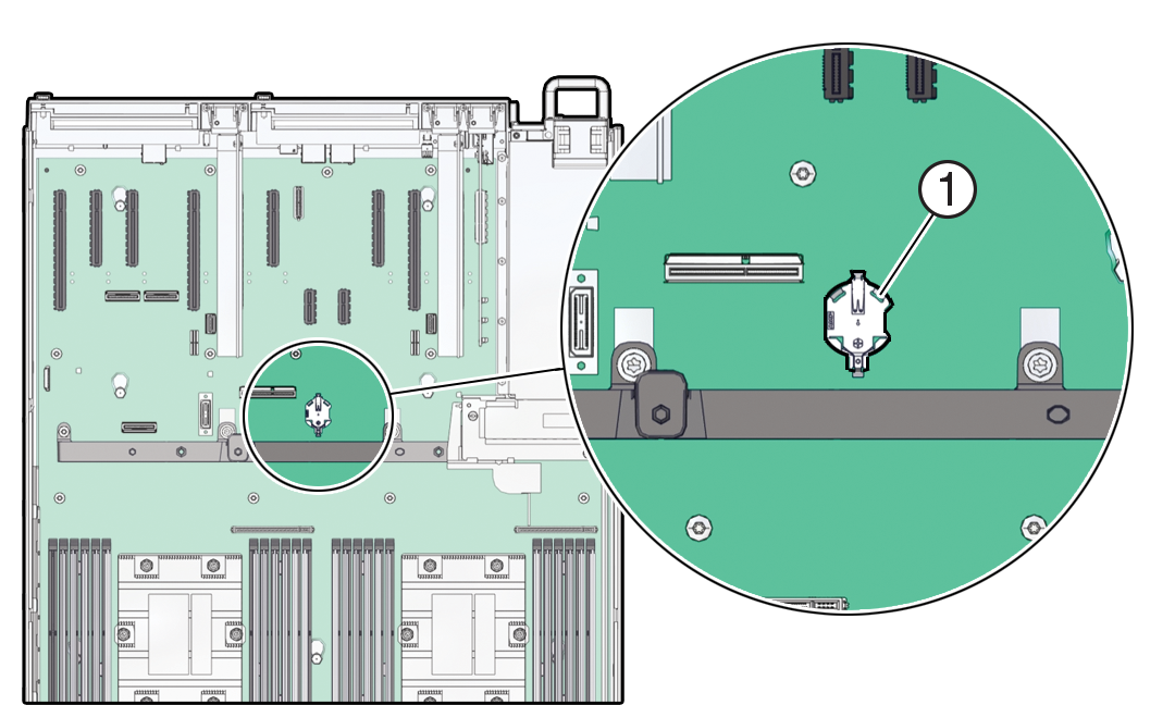
  2. Locate the battery and RTC battery retainer on the server motherboard.

    Note:

    Coin battery retainer types that are mounted in the RTC battery motherboard location may be different.
    Description of mm-10909_battery-location.png follows
    Description of the illustration mm-10909_battery-location.png
  3. Remove the battery from the battery connector.

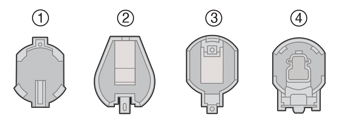
    There are serveral possible battery connector types used for the system as shown in the following illustration. Instructions for battery replacement can vary depending on the connector in your system.

    Description of mm-10910_battery-types.png follows
    Description of the illustration mm-10910_battery-types.png
    Callout Description

    1

    796136-1 Top-Load Battery Connector (TE)

    2

    1093TR Top-Load Battery Connector

    3

    1070TR Top-Load Battery Connector

    4

    S8421 Top-Load Battery Connector

    Do one of the following detailed instructions for the type of RTC battery retainer on the server motherboard.

    • Remove the battery from the 796136-1 Top-Load Battery Connector (TE) as follows:

      Each connector consists of a housing with a positive contact and a negative contact. The floor of the housing is embossed with a `+' to designate the positive contact. The connector features four lips for positive retention of the battery.

      1. Support the connector by grasping the "positive" end of the connector with two fingers and then pushing the battery toward the positive end of the connector [1]. Slightly move the lips at the negative end of the connector away from the battery to dislodge it from the connector.

        Note:

        CAUTION! The connector must be supported, otherwise damage to the soldered contacts could occur.
        Description of mm-10908_battery-remove_8.png follows
        Description of the illustration mm-10908_battery-remove_8.png
      2. Once the batter has been dislodged, remove the battery from the connector [2].
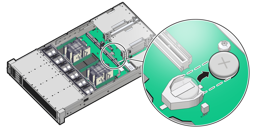
    • Remove the battery from the 1093TR Top-Load Battery Connector as follows:
      1. Using your fingers or a non-conducting stylus, gently pry up the edge of the battery from underneath the negative spring tab just enough to dislodge it from the connector.
      2. Then slide the battery out from under the negative spring tab and away from the connector.
      Description of aog-269_battery-remove.png follows
      Description of the illustration aog-269_battery-remove.png
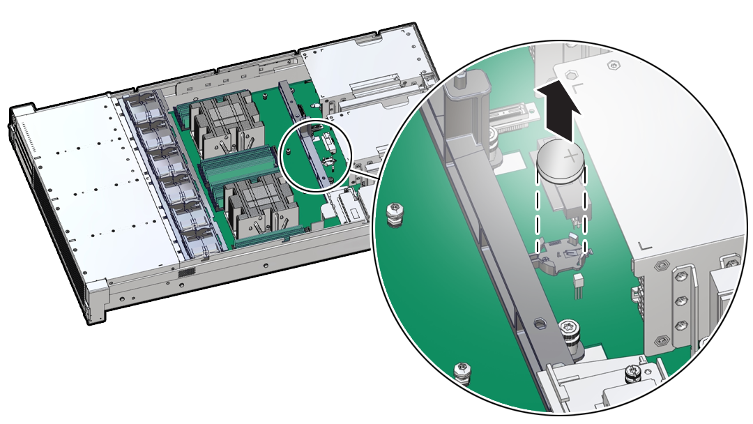
    • Remove the battery from other Top-Load Battery Connectors as follows.
      1. To dislodge the battery from the retainer, place your finger under the side of the battery nearest the rear of the server.

      2. Gently lift the battery up and out of the connector.

      Description of mm-10531_battery-remove-1.png follows
      Description of the illustration mm-10531_battery-remove-1.png

Install the Battery

  1. Unpack the replacement RTC battery.
  2. Press the new battery into the battery retainer.
    • Install the battery into the 796136-1 Top-Load Battery (TE) Connector as follows:

      Each connector consists of a housing with a positive contact and a negative contact. The floor of the housing is embossed with a `+' to designate the positive contact. The connector features four lips for positive retention of the battery.

      1. Support the connector by grasping the positive end of the connector [1]. Then, while holding the battery at an angle with the positive ‘+’ side facing up, slide the battery under the lips at the positive end of the connector [1].

        Note:

        CAUTION! The connector must be supported, otherwise damage to the soldered contacts could occur.
        Description of mm-10908_battery-install_8.png follows
        Description of the illustration mm-10908_battery-install_8.png
      2. Gently push the battery onto the floor of the connector housing until the battery is fully seated [2]. There should be an audible “snap.”
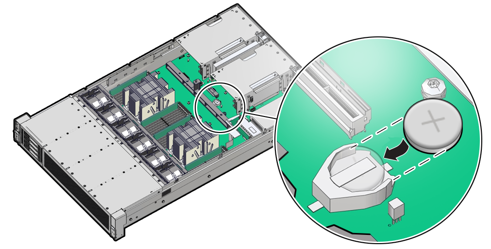
    • Install the battery into the 1093TR Top-Load Battery Connector as follows:
      1. Gently slide the battery under the negative spring tab of the connector.
      2. Slide the battery to the back of the connector and push the battery into the connector housing until the battery is fully seated. There should be an audible “snap.”
      Description of aog-269a_battery-install.png follows
      Description of the illustration aog-269a_battery-install.png
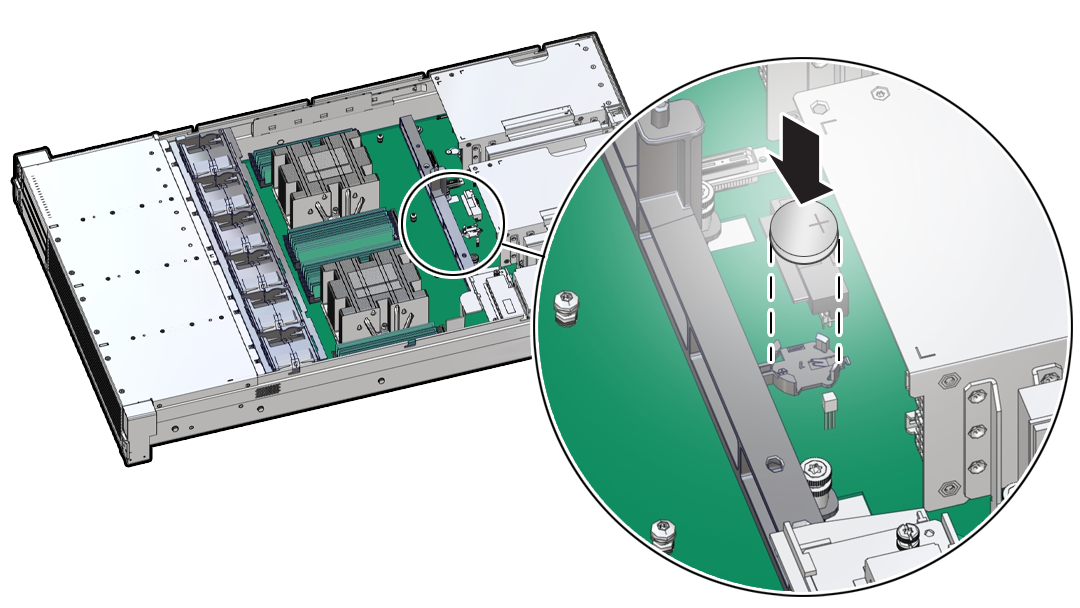
    • Install the battery into the other Top-Load Battery Connectors as follows:
      1. While holding the battery at an angle with the positive ‘+’ side facing up, slide the battery under the lips at the back of the connector
      2. Then gently push the battery onto the floor of the housing until the battery is fully seated. There should be an audible “snap.”
      Description of mm-10532_battery-install.png follows
      Description of the illustration mm-10532_battery-install.png
  3. Return the server to operation.
    1. Install the server top cover.
    2. Return the server to the normal rack position.
    3. Reconnect the power cords to the server power supplies, and power on the server.
    4. Verify that the System OK LED indicator is lit.

      Note:

      If the service processor is configured to synchronize with a network time server using the Network Time Protocol (NTP), the Oracle ILOM SP clock is reset as soon as the server is powered on and connected to the network. Otherwise, proceed to the next step.
  4. If the service processor is not configured to use NTP, you must do one of the following: