Chapter 6 Extending Oracle Private Cloud Appliance - Additional Compute Nodes
Extension of Oracle Private Cloud Appliance involves increasing the number of compute nodes within a rack to maximize the number of virtual machines that are capable of running on the appliance and to increase the processing power and memory available to existing virtual machines. The process of extending the Oracle Private Cloud Appliance in this way requires that you install additional servers into the rack. This operation does not require that the system is powered down, but physical changes are made to the system. Therefore you should review the task map provided in Section 6.1, “Extending Compute Capacity Task Map” before continuing. Each step to perform the operation is described in detail in this chapter.
This chapter explains how to extend your Oracle Private Cloud Appliance by adding compute nodes to the system. After hardware installation, when compute node provisioning has completed, the servers are automatically added to the default tenant group Rack1_ServerPool. Depending on the tenant group configuration in the environment, you should add each newly provisioned server to the appropriate tenant group.
6.1 Extending Compute Capacity Task Map
Table 6.1 describes the steps for extending the Oracle Private Cloud Appliance at your site by installing additional compute nodes within the rack.
|
Step |
Description |
Links |
|---|---|---|
|
1 |
Review safety guidelines and site checklists. |
|
|
2 |
Review safety precautions for rack-mounting a server. |
|
|
3 |
Prepare to add the server to the rack, including:
|
|
|
4 |
Install the server into the rack, including:
|
6.2 Review Safety Guidelines
Before expanding Oracle Private Cloud Appliance, read the following important safety information:
-
Important Safety Information for Oracle's Hardware Systems (7063567)
6.3 Rack-mount Safety Precautions
This section describes rack-mount safety precautions you must follow when installing a compute node into your Oracle Private Cloud Appliance.
Leveling feet position: When unpacking at the installation site, or when repackaging and moving the rack to a new location, verify that the leveling feet are up before moving the rack.
Stabilize rack: Deploy the anti-tilt bar on the equipment rack before starting an installation.
Shipping brackets: The rack shipping brackets are not for use for bracing or anchoring the rack during seismic events.
Equipment loading: Always load equipment into a rack from the bottom up so that the rack does not become top-heavy and tip over. Deploy your rack anti-tilt bar to prevent the rack from tipping during equipment installation.
Lifting equipment: Oracle Server X8-2 weighs approximately 45 lbs (20.41 kg). Two people are needed to mount the server into the rack enclosure.
Communicate instructions: When performing a two-person procedure, communicate your intentions clearly to the other person before, during, and after each step to minimize confusion.
Elevated operating ambient temperature: If you install the server in a closed or multi-unit rack assembly, the operating ambient temperature of the rack environment might be higher than the room ambient temperature. Install the equipment in an environment compatible with the maximum ambient temperature (Tma) specified for the server. For information, refer to Section 2.5, “Ventilation and Cooling Requirements”.
Reduced airflow: Install the equipment in a rack so that it does not compromise the amount of airflow required for safe operation of the equipment.
Mechanical loading: Mount the equipment in the rack so that it does not cause a hazardous condition due to uneven mechanical loading.
Circuit overloading: Consider the connection of the equipment to the supply circuit and the effect that overloading the circuits might have on over-current protection and supply wiring. Also consider the equipment nameplate power ratings used when you address this concern.
Reliable earthing: Maintain reliable earthing of rackmounted equipment. Pay attention to supply connections other than direct connections to the branch circuit (for example, use of power strips).
Mounted equipment: Do not use slide-rail-mounted equipment as a shelf or a workspace.
6.4 Prepare to Add a Server
This section describes the preparation steps to perform before installing an additional compute node as part of your Oracle Private Cloud Appliance.
When adding expansion nodes, always populate the compute rack units starting from the bottom most open slot, and work your way up. If you do not populate the rack units in the right order, the controller software may no longer report the correct status of the rack components.
6.4.1 ESD Precautions
Electronic equipment is susceptible to damage by static electricity. To prevent electrostatic discharge (ESD) when you install or service the server:
-
Use a grounded antistatic wrist strap, foot strap, or equivalent safety equipment.
-
Place components on an antistatic surface, such as an antistatic discharge mat or an antistatic bag.
-
Wear an antistatic grounding wrist strap connected to a metal surface on the chassis when you work on system components.
Equipment damage: Electrostatic damage can permanently disable the system or require repair by authorized service technicians.
Before installing the server, read the safety information in the Oracle Server X8-2 Safety and Compliance Guide, as well as the Important Safety Information for Oracle's Hardware Systems.
6.4.2 Unpack the Server Upgrade Kit
Perform the following procedure to unpack the server upgrade kit.
-
Inspect the shipping cartons for evidence of physical damage. If a shipping carton appears damaged, request that the carrier agent be present when the carton is opened. Keep all contents and packing material for the agent inspection.
-
Remove the packaging from the Oracle Private Cloud Appliance Expansion Node upgrade kit.
-
Verify that all items are included. The upgrade kit should contain the following:
-
Oracle Server
-
Cable management arm assembly with installation instructions
-
Rackmount kit including rack rails, mounting brackets, screws and Rackmounting Template
-
Getting Started Guide
-
Legal and safety documents
NoteCables are not included in the server upgrade kit. Oracle Private Cloud Appliance comes with pre-installed and labeled cables for all rack units. These should not be unplugged or removed from the rack.
-
6.4.3 Prepare the Appliance Rack
Perform the following procedure to prepare the rack.
To reduce the risk of personal injury, stabilize the rack cabinet and extend all anti-tilt devices before performing this procedure.
-
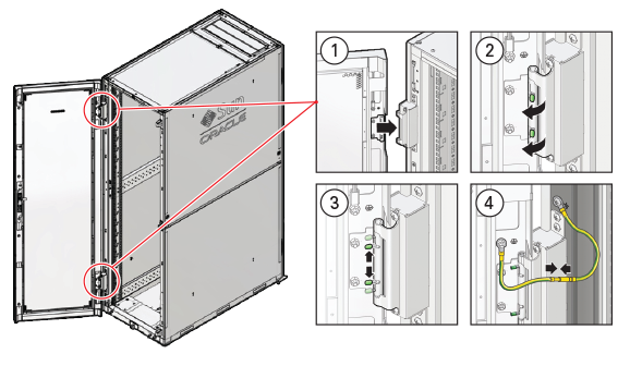
Remove the Oracle Private Cloud Appliance front and rear rack doors, as follows:
-
Unlock and open the front and rear rack doors.
-
Detach the top and bottom grounding straps by separating the banana jacks (1).
-
Unlatch the bottom hinge, then the top hinge.
-
Pinch the two studs on the hinge towards the center of the hinge (2).
-
Rotate the studs away from the door (3) so that they stay in place and the hinge remains unlatched.
-
-
Lift the door away from the cabinet (4).
-
Repeat these steps for the two rear doors.
These steps are illustrated in Figure 6.1.
CautionThe doors are heavy. Have one person hold the door in place while the other operates the hinge latching mechanism. Execute the steps carefully and in the correct order, to avoid damage to the hinges.
Figure 6.1 Removing the Rack Doors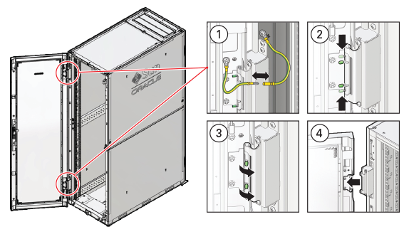
Table 6.2 Figure LegendItem
Description
1
Detaching the grounding cables.
2
Pinching the hinge studs.
3
Rotating the studs away from the door.
4
Lifting the door away from the cabinet.
-
-
Remove the filler panel(s) where the upgrade server will be installed.
The filler panels have snap-in attachments. No screwdriver is required to remove them.
-
Remove the cable tray that holds the pre-installed cables in place at the rear side of the rack. See Figure 6.2
-
Detach the pre-installed cables from the cable tray on the rack unit for the new expansion node.
-
Use a No. 2 Phillips screwdriver to remove the M6 screws from the cable tray.
-
Remove the cable tray from the rack. Save cable tray and screws for future use.
Figure 6.2 Removing the Cable Tray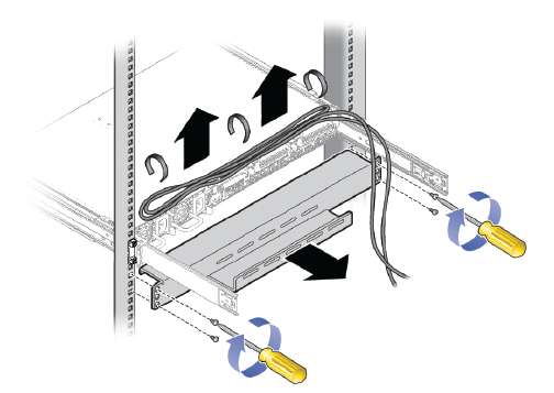
-
6.5 Install the Server Into the Rack
This section describes the steps to install an additional compute node as part of your Oracle Private Cloud Appliance.
6.5.1 Install Mounting Brackets
Perform the following procedure to install mounting brackets onto the sides of the server.
-
Position a mounting bracket against the chassis so that the slide-rail lock is at the server front, and the five keyhole openings on the mounting bracket are aligned with the five locating pins on the side of the chassis. See Figure 6.3.
Figure 6.3 Aligning the Mounting Bracket With the Server Chassis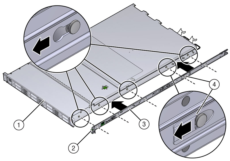
Table 6.3 Figure LegendItem
Description
1
Chassis front
2
Slide-rail lock
3
Mounting bracket
4
Mounting bracket clip
-
With the heads of the five chassis locating pins protruding through the five keyhole openings in the mounting bracket, pull the mounting bracket toward the front of the chassis until the mounting bracket clip locks into place with an audible click.
-
Verify that the rear locating pin has engaged the mounting bracket clip.
-
Repeat these steps to install the remaining mounting bracket on the other side of the server.
6.5.2 Attach Slide-Rail Assemblies
Perform the following procedure to attach slide-rail assemblies to the rack.
-
Orient the slide-rail assembly so that the ball-bearing track is forward and locked in place.
Figure 6.4 Orienting the Slide-Rail With the Ball-Bearing Track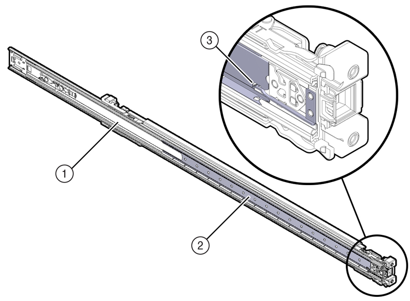
Table 6.4 Figure LegendItem
Description
1
Slide-rail
2
Ball-bearing track
3
Locking mechanism
-
Starting with either the left or right side of the rack, align the rear of the slide-rail assembly against the inside of the rear rack rail, and push until the assembly locks into place with an audible click. See Figure 6.5.
Figure 6.5 Aligning the Slide-Rail Assembly With the Rack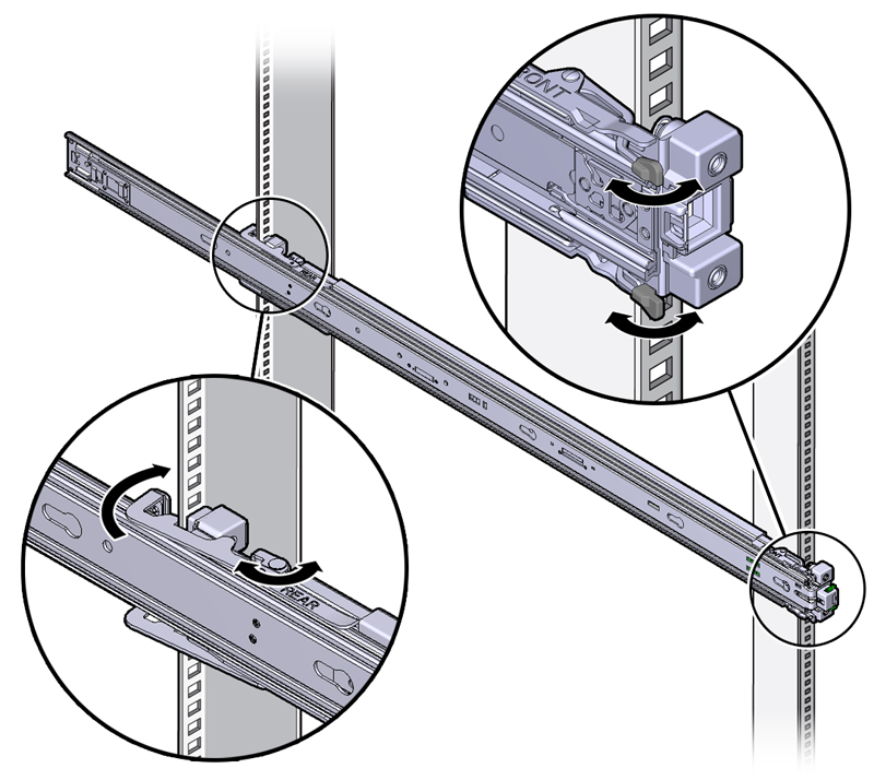
-
Align the front of the slide-rail assembly against the outside of the front rack rail, and push until the assembly locks into place with an audible click. See Figure 6.5.
-
Repeat these steps to attach the slide-rail assembly to the other side of the rack.
6.5.3 Install the Server Into the Slide-Rail Assemblies
Perform the following procedure to install the server, with mounting brackets, into the slide-rail assemblies that are mounted to the rack.
This procedure requires a minimum of two people because of the weight of the server. Attempting this procedure alone could result in equipment damage or personal injury.
Always load equipment into a rack from the bottom up so that the rack will not become top-heavy and tip over. Extend your rack's anti-tilt bar to prevent the rack from tipping during equipment installation.
-
Push the slide-rails as far as possible into the slide-rail assemblies in the rack.
-
Position the server so that the rear ends of the mounting brackets are aligned with the slide-rail assemblies that are mounted in the rack. See Figure 6.6.
-
Insert the mounting brackets into the slide-rails, and then push the server into the rack until the mounting brackets encounter the slide-rail stops (approximately 30 cm, or 12 inches).
Figure 6.6 Inserting the Server With Mounting Brackets Into the Slide-Rails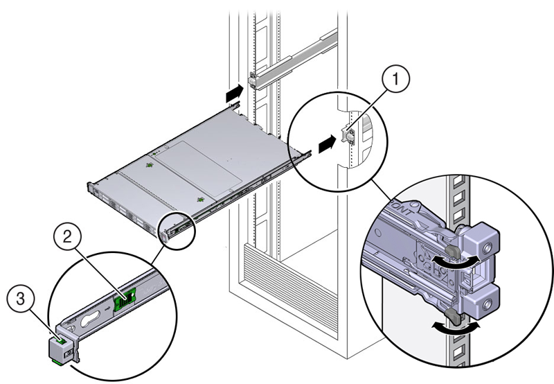
Table 6.5 Figure LegendItem
Description
1
Inserting mounting bracket into slide-rail
2
Slide-rail release button
3
Slide-rail lock
-
Simultaneously push and hold the green slide-rail release buttons on each mounting bracket while you push the server into the rack. Continue pushing the server into the rack until the slide-rail locks (on the front of the mounting brackets) engage the slide-rail assemblies. See Figure 6.7.
You will hear an audible click.
Figure 6.7 Sliding the Server Into the Rack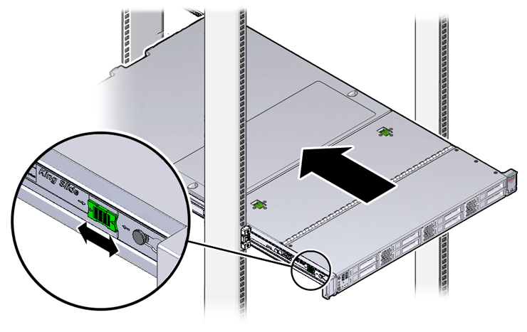
6.5.4 Install the Cable Management Arm
Perform the following procedure to install the cable management arm (CMA) to rear of the server.
-
Unpack the CMA.
-
To make it easier to install the CMA, extend the server approximately 13 cm (5 inches) out of the front of the rack.
-
Take the CMA to the back of the equipment rack, and ensure that you have adequate room to work at the back of the server.
NoteReferences to “left” or “right” in this procedure assume that you are facing the back of the equipment rack.
NoteThroughout this installation procedure, support the CMA and do not allow it to hang under its own weight until it is secured at all four attachment points.
-
Insert the CMA's connector A into the front slot on the left slide-rail until it locks into place with an audible click. See Figure 6.8, frames 1 and 2.
The connector A tab (see call-out 1) goes into the slide-rail's front slot (call-out 2).
Gently tug on the left side of the front slide bar to verify that connector A is properly seated.
Figure 6.8 Installing Connector A Into the Left Slide-Rail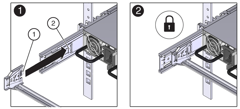
Table 6.6 Figure LegendItem
Description
1
Connector A tab
2
Left slide-rail front slot
-
Insert the CMA's connector B into the front slot on the right slide-rail until it locks into place with an audible click. See Figure 6.9, frames 1 and 2.
The connector B tab (call-out 1) goes into the slide-rail front slot (call-out 2).
Gently tug on the right side of the front slide bar to verify that connector B is properly seated.
Figure 6.9 Installing Connector B Into the Right Slide-Rail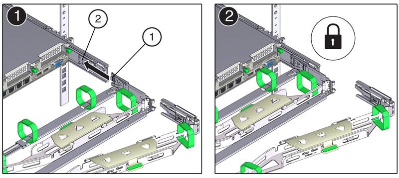
Table 6.7 Figure LegendItem
Description
1
Connector B tab
2
Right slide-rail front slot
-
To install the CMA's connector C into the right slide-rail, perform the following steps:
-
Align connector C with the slide-rail so that the locking spring (call-out 1) is positioned inside (server side) of the right slide-rail. See Figure 6.10, frame 1.
Figure 6.10 Installing Connector C Into the Right Slide-Rail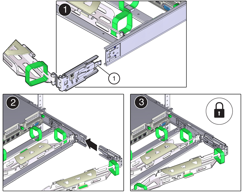
Table 6.8 Figure LegendItem
Description
1
Connector C locking spring
-
Insert connector C into the right side-rail until it locks into place with an audible click (frames 2 and 3).
-
Gently tug on the right side of the CMA's rear slide bar to verify that connector C is properly seated.
-
-
To prepare the CMA's connector D for installation, remove the tape that secures the slide-rail latching bracket to connector D and ensure that the latching bracket is properly aligned with connector D. See Figure 6.11, frames 1 and 2.
NoteThe CMA is shipped with the slide-rail latching bracket taped to connector D. You must remove the tape before you install this connector.
Figure 6.11 Aligning the CMA Slide-Rail Latching Bracket With Connector D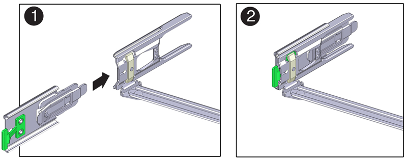
-
While holding the slide-rail latching bracket in place, insert connector D and its associated slide-rail latching bracket into the left slide-rail until connector D locks into place with an audible click. See Figure 6.12, frames 1 and 2.
NoteWhen inserting connector D into the slide-rail, the preferred and easier method is to install connector D and the latching bracket as one assembly into the slide-rail.
Gently tug on the left side of the CMA's rear slide bar to verify that connector D is properly seated.
Figure 6.12 Installing Connector D Into the Left Slide-Rail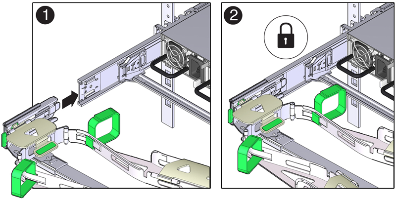
NoteThe slide-rail latching bracket has a green release tab. This tab is used to release and remove the latching bracket so that you can remove connector D.
-
Gently tug on the four CMA connection points to ensure that the CMA connectors are fully seated before you allow the CMA to hang by its own weight.
-
To verify that the slide-rails and the CMA are operating properly before routing cables through the CMA, perform the following steps:
-
Extend the server from the front of the rack until the CMA is fully extended.
CautionTo reduce the risk of personal injury, stabilize the rack cabinet and extend all anti-tilt devices before extending the server from the rack.
-
Simultaneously pull and hold the two green release tabs (one on each side of the server) toward the front of the server (see the following figure) while you push the server into the rack. As you push the server into the rack, verify that the CMA retracts without binding. See Figure 6.13.
NoteTo pull the green release tabs, place your finger in the center of each tab, not on the end, and apply pressure as you pull the tab toward the front of the server.
Figure 6.13 Location of the Slide-Rail Release Tabs
-
Continue pushing the server into the rack until the slide-rail locks (on the front of the server) engage the slide-rail assemblies.
You will hear an audible click when the server is in the normal rack position.
-
-
Connect the cables to the server, as required.
Instructions for connecting server cables are provided in Section 6.5.5, “Cable the Server”.
6.5.5 Cable the Server
After the server is installed in the rack and proper cable management arm (CMA) operation is verified, perform the procedures in this section to cable the server.
If you are installing more than one server into the rack, perform the procedures in the previous sections for each server before performing the cabling steps in this section.
You should observe the following guidelines when attaching cables to a newly rack-mounted server:
-
Do not remove existing cable connections in the rack.
-
Attach and route cables in the CMA and rear panel one server at a time. Do not slide out more than one server at a time.
-
Start from the bottom of the rack, and work upward. Route cables through the CMA with the dongle on the top and power cables on the bottom.
The Oracle Private Cloud Appliance rack is entirely pre-cabled for all components, including future compute nodes. Cable bundles are cable-tied to the correct rack unit for each future server. You should not modify any of the cabling on the already installed components. For detailed cabling information, see Appendix B, Cabling Reference.
-
Connect the pre-installed power and data cables of the appropriate rack unit to the back of the expansion node. The cables are labeled for your convenience, and should be connected according to Figure 6.14.
Figure 6.14 Server Cabling Requirements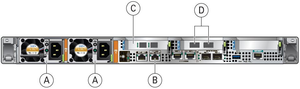
Table 6.9 Figure LegendItem
Description
A
Power supplies
B
NET0Ethernet portC
Optional Fibre Channel HBA
CautionPhysical Fibre Channel expansion cards are available as an option for Oracle Server X8-2 or newer compute nodes. The appliance rack does not contain pre-installed Fibre Channel cables.
D
Internal appliance data network connectors
CautionDepending on the physical network architecture of your appliance, the connectors are either InfiniBand or Ethernet ports. A specific server model is available for each architecture type.
-
Open the CMA cable covers, route server cables through the CMA's cable troughs, close the cable covers, and secure the cables with the six Velcro straps. See Figure 6.15.
-
First through the front-most cable trough.
-
Then through the small cable trough.
-
Then through the rear-most cable trough.
NoteWhen securing the cables with the Velcro straps located on the front slide bar, ensure that the Velcro straps do not wrap around the bottom of the slide bar; otherwise, expansion and contraction of the slide bar might be hindered when the server is extended from the rack and returned to the rack.
Figure 6.15 CMA With Cables Installed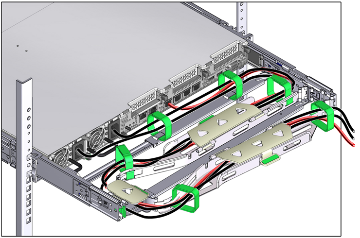
-
-
Ensure that the secured cables do no extend above the top or below the bottom of the server to which they are attached; otherwise, the cables might snag on other equipment installed in the rack when the server is extended from the rack or returned to the rack.
NoteIf necessary, bundle the cables with additional Velcro straps to ensure that they stay clear of other equipment. If you need to install additional Velcro straps, wrap the straps around the cables only, not around any of the CMA components; otherwise, expansion and contraction of the CMA slide bars might be hindered when the server is extended from the rack and returned to the rack.
-
Verify the operation of the CMA with all cables installed.
NoteOracle recommends that two people execute this step. One person to move the server in and out of the rack, and another person to observe the cable and CMA operation.
-
Slowly pull the server out of the rack until the slide rails reach their stop.
-
Inspect the attached cables for any binding or kinks.
-
Verify that the CMA extends fully from the slide rails.
-
-
Push the server back into the rack.
-
Simultaneously pull and hold the two green release tabs (one on each side of the server) toward the front of the server while you push the server into the rack. See Figure 6.13.
NoteTo pull the green release tabs, place your finger in the center of each tab, not on the end, and apply pressure as you pull the tab toward the front of the server.
-
Verify that the CMA retracts without binding.
-
-
Repeat the previous steps for each additional server that you add to the rack.
The Oracle Private Cloud Appliance controller software detects that one or more new compute nodes are present in the rack. It automatically powers on the new hardware and executes the provisioning procedure. The expansion compute nodes are incorporated seamlessly into the active system. This requires no further interventions by an administrator.
6.5.6 Replace the Rack Doors
Perform the following procedure to replace the rack front and rear doors:
-
Lift the door into place, and align the pins on the door with the sleeve on the cabinet (1).
-
On the top hinge, rotate the two studs on the hinge away from the center of the hinge (2). The pins snap into place (3). Do the same with the bottom hinge.
-
Repeat these steps to reinstall the other rack doors.
-
Reconnect all grounding straps on all doors (4).
-
Close the doors. Optionally, lock the doors.
These steps are illustrated in Figure 6.1.
The doors are heavy. Have one person hold the door in place while the other operates the hinge latching mechanism. Execute the steps carefully and in the correct order, to avoid damage to the hinges.
|
Item |
Description |
|---|---|
|
1 |
Lifting the door into place. |
|
2 |
Rotating the hinge studs away from the center. |
|
3 |
Pins on the latching mechanism snap into place. |
|
4 |
Attaching the grounding cables. |