Chapter 3 Network Requirements
Oracle Private Cloud Appliance exists in two different types of network architecture. One is built around a physical InfiniBand fabric; the other relies on physical high speed Ethernet connectivity. While the two implementations offer practically the same functionality, there are visible hardware and configuration differences. Consequently, each network architecture has its own requirements.
New systems with factory-installed Controller Software Release 2.4.x have an Ethernet-based network architecture. For customers upgrading a system with InfiniBand-based network architecture to Release 2.4.2 or newer, those network requirements are included as well. Refer to the sections that apply to your appliance.
The networking infrastructure in Oracle Private Cloud Appliance and Oracle Private Cloud at Customer is integral to the appliance and shall not be altered. The networking does not integrate into any data center management or provisioning frameworks such as Cisco ACI, Network Director, or the like, with the exception of the ability to query the switches using SNMP in read-only mode. No changes to the networking switches in Oracle Private Cloud Appliance and Oracle Private Cloud at Customer are supported unless directed to do so by a KM note or Oracle Support.
3.1 Network Connection and IP Address Requirements for Ethernet-based Systems
This section describes the network connection requirements and IP address requirements to connect the Oracle Private Cloud Appliance with Ethernet-based network architecture to your existing network infrastructure.
3.1.1 Network Connection Requirements for Ethernet-based Systems
Before installation, you must run network cables from your existing network infrastructure to the Oracle Private Cloud Appliance installation site.
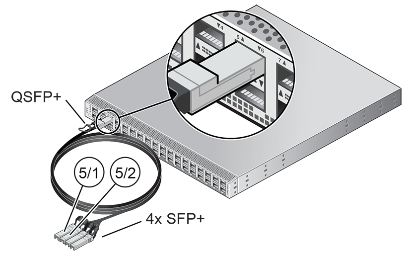
You must connect 2 high-speed Ethernet ports on each spine Cisco Nexus 9336C-FX2 Switch to your data center public Ethernet network. These are ports 5/1 and 5/2, which are configured at 10Gbit and intended as the default connection for appliance management and setup. This configuration is locked and must remain at 10Gbit; it requires breakout cables with a QSFP+ transceiver on the spine switch end and four SFP+ transceivers on the other end.
Figure 3.1 shows the location of the two 10 GbE breakout ports on the spine switches, which must be connected to the data center network.
It is critical that both spine switches have two 10GbE connections each to a pair of next-level data center switches. This configuration with four cable connections provides redundancy and load splitting at the level of the spine switches, the 10GbE ports and the data center switches. This outbound cabling from the pair of spine Cisco Nexus 9336C-FX2 Switches should be crossed: each spine switch must be connected to two next-level data center switches. The cabling pattern plays a key role in the continuation of service during failover scenarios.
3.1.1.1 Data Center Switch Configuration Notes
When configuring the data center switches to accept incoming Oracle Private Cloud Appliance uplinks – the default uplinks as well as any custom uplinks you define – take these notes into account.
-
All uplinks, default and customer, are configured to use link aggregation (LACP). All four switch ports included in an uplink configuration – two per spine switch – must belong to the same link aggregation group (LAG), also known as port channel. The switch ports on the data center side of the uplinks must be configured accordingly.
-
The data center switch ports to which the Oracle Private Cloud Appliance uplinks are connected, must be set to trunk mode.
-
The spine switches operate with the Virtual Port Channel (vPC) feature enabled. Therefore, the standard Spanning Tree Protocol (STP) is not supported in the data center network ports connected to the Oracle Private Cloud Appliance. If spanning tree protocol is required on the switch ports connected to Oracle Private Cloud Appliance, you must use the Multiple Spanning Tree Protocol (MSTP) or a compatible protocol.
-
Auto-negotiation is not available for uplink ports. Transfer speed must be specified on the customer switches' end. For the default uplink ports, this is 10Gbit/s.
Example
Below is an example of a custom uplink configuration for your reference.
In this example, port 3 on both spine switches is split into 4x 25Gbit. Ports 3:1 and 3:2 are cross-cabled to a pair of ToR switches. Like the internal spine switches of the Oracle Private Cloud Appliance, the two ToR switches have the virtual port channel (vPC) feature enabled, allowing ports from both switches to operate within the same port channel.
These are the key configuration parameters:
-
The vPC feature must be enabled on both ToR switches: vpc domain 1.
-
Ports 49 and 50 on both ToR switches must belong to port channel 200.
-
Port channel 200 on both ToR switches must belong to virtual port channel 200.
-
Port channel parameters, such as MTU, speed and spanning tree filter, must be identical on both ToR switches.
-
All port channel and switch port interfaces are set to trunk mode.
ToR switch A configuration:
feature lacp
feature vpc
vpc domain 1
    peer-switch
    role priority 1
    peer-keepalive destination <ToR-B_IP> source <ToR-A_IP>
    peer-gateway
    layer3 peer-router
    ip arp synchronize

interface port-channel 200
    description "Uplink PCA 3:1 3:2 port channel"
    switchport mode trunk
    switchport trunk allowed vlan 1-4094     ### optional, typical default setting
    switchport trunk native vlan 500         ### optional, for data center vlan
    speed 25000
    mtu 9216
    vpc 200

interface Ethernet 1/49
    description "PCA spine 1 Port 3:1"
    switchport mode trunk
    switchport trunk allowed vlan 1-4094     ### optional, typical default setting
    switchport trunk native vlan 500         ### optional, for data center vlan
    speed 25000
    mtu 9216
    channel-group 200 mode active

interface Ethernet 1/50
    description "PCA spine 2 Port 3:1"
    switchport mode trunk
    switchport trunk allowed vlan 1-4094     ### optional, typical default setting
    switchport trunk native vlan 500         ### optional, for data center vlan
    speed 25000
    mtu 9216
    channel-group 200 mode active
ToR switch B configuration:
feature lacp
feature vpc
vpc domain 1
    peer-switch
    role priority 2
    peer-keepalive destination <ToR-A_IP> source <ToR-B_IP>
    peer-gateway
    layer3 peer-router
    ip arp synchronize

interface port-channel 200
    description "Uplink PCA 3:1 3:2 port channel"
    switchport mode trunk
    switchport trunk allowed vlan 1-4094     ### optional, typical default setting
    switchport trunk native vlan 500         ### optional, for data center vlan
    speed 25000
    mtu 9216
    vpc 200

interface Ethernet 1/49
    description "PCA spine 1 Port 3:2"
    switchport mode trunk
    switchport trunk allowed vlan 1-4094     ### optional, typical default setting
    switchport trunk native vlan 500         ### optional, for data center vlan
    speed 25000
    mtu 9216
    channel-group 200 mode active

interface Ethernet 1/50
    description "PCA spine 2 Port 3:2"
    switchport mode trunk
    switchport trunk allowed vlan 1-4094     ### optional, typical default setting
    switchport trunk native vlan 500         ### optional, for data center vlan
    speed 25000
    mtu 9216
    channel-group 200 mode active
3.1.1.2 Appliance Uplink Configuration
The uplinks are the system's physical connections between the spine switches and the data center network or top-of-rack (ToR) switches. Ports 1-4 on the spine switches are reserved for customer use. The uplink configuration must comply with requirements and restrictions, which are explained in this section.
For the purpose of high availability, uplink ports are always configured in pairs on each spine switch. Each port pair must operate in one of these modes, using the appropriate transceivers and cables:
-
100Gbit full port bandwidth
-
40Gbit full port bandwidth
-
4x 25Gbit with 4-way breakout cable
-
4x 10Gbit with 4-way breakout cable
The Cisco Nexus 9336C-FX2 Switch ports are of the QSFP28 100Gbit type. Depending on your data center network infrastructure, each of the customer-reserved ports can be used at maximum bandwidth or split into 25Gbit (SFP28) or 10Gbit (SFP+). External Ethernet connections from the Oracle Private Cloud Appliance require a minimum speed of 10Gbit/s. Verify the cable and transceiver requirements for your intended configuration. Only Oracle-supplied transceivers should be installed in the Oracle Private Cloud Appliance spine switches.
For custom networks through spine switch ports 1-4, the port pairs and their mode of operation are configured through the Oracle Private Cloud Appliance CLI. The configuration of the default uplink ports on spine switch port 5 cannot be modified: it operates in 4x 10Gbit mode with ports 5/1 and 5/2 cross-cabled to the ToR switches, while ports 5/3 and 5/4 remain unused.
Spine switch ports 1 and 2, and ports 3 and 4, must be configured at the same time. If one port uses a breakout cable, then the other port must also be set up that way. All four ports on the same breakout cable must be set to the same speed, but different breakout cables can be set up for different speeds.
This results in the following supported configurations:
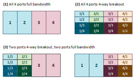
Each port pair on each individual spine switch must be cross-connected to two ToR switches. Each port pair that is configured for external connectivity – identically on both spine switches by definition – corresponds with a separate VLAN. The deduplication of ports and switches is primarily for redundancy; the VLANs already separate traffic.
The spine switches allow a maximum supported number of 8 custom uplinks, corresponding with 16 port pairs. This number does not include the default uplink.
3.1.1.3 Optional Data Center Administration Network Uplink
In addition to the public Ethernet connection, you may connect the Cisco Nexus 9348GC-FXP Switch to a management or machine administration network at your installation site. If you choose to use such an uplink, consider it as a long-term alternative to the temporary workstation connection described in Section 3.1.2, “IP Address Requirements for Ethernet-based Systems”. Configure the administration uplink after the initialization of the appliance, when the appliance network settings have been applied.
Connect port 2 on the Cisco Nexus 9348GC-FXP Switch.
Make sure that the data center Ethernet switch used in this connection is configured to prevent DHCP leakage to the 192.168.4.0/24 subnet used by Oracle Private Cloud Appliance. Do not connect to any network with any kind of broadcast services in addition to DHCP.
For the bastion host, which is the name used to describe the machine that is permanently connected to the data center administration network, use the IP address 192.168.4.199 and assign it statically to its network interface. Make sure there is no other machine on the same subnet using the same IP address and causing IP conflicts.
A connection to the appliance internal management network, either directly into the Cisco Nexus 9348GC-FXP Switch or through an additional Ethernet switch in the data center, is not required to access the appliance management functionality of the Oracle Private Cloud Appliance Dashboard. The primary role of the appliance internal management network is to allow the controller software on the management nodes to interact with the compute nodes and other rack components. Connecting to this network from outside the appliance allows you to gain direct administrator access to each component, for example to control the ILOMs.
Do not make any changes to anything on this network unless directed to do so by Oracle Support.
The Oracle Private Cloud Appliance Dashboard and Oracle VM Manager UI, in contrast, are not accessed over the internal management network, but through the management node cluster's virtual IP address. The virtual IP address is public, in the sense that it should be accessible from within your data center network. You reserve this IP address in your data center network in advance, as described in Section 3.3, “General Network Configuration”, and then configure it in the appliance network settings during software initialization. Instructions for first access to the Oracle Private Cloud Appliance Dashboard are provided in Section 5.3.5, “Connect the Appliance to the Network”.
3.1.2 IP Address Requirements for Ethernet-based Systems
The Oracle Private Cloud Appliance requires a large number of private IP addresses. These are reserved for the normal operation and future expansion of the system and cannot be reconfigured. While system-level subnets and IPs should be avoided, the customer is allowed to choose the network configuration for external and virtual machine traffic that suits their requirements.
For lists of default IP addresses that are preassigned to your Oracle Private Cloud Appliance, see Appendix A, Default IP Addresses.
To gain initial access to the Oracle Private Cloud Appliance Dashboard, you must connect a terminal or workstation with a web browser directly to the internal management network. Connect an Ethernet cable to the available port 48 in the Cisco Nexus 9348GC-FXP Switch, and statically configure the wired network connection of the workstation to use the IP address 192.168.4.254.
The IP address 192.168.4.254 and switch port 48 have been reserved specifically for the purpose of connecting a workstation during the first boot, initialization and provisioning of the appliance.
During the initial software configuration of the Oracle Private Cloud Appliance, you configure the network settings of the management nodes. For this purpose, you should reserve three IP addresses in the public (data center) network: one for each management node, and one to be used as virtual IP address shared by both management nodes. If the data center network traffic is tagged, make sure that the VLAN ID is also provided as part of the configuration. The virtual IP address provides access to the Dashboard once the software initialization is complete.
To avoid network interference and conflicts, you must ensure that the data center network does not overlap with any of the infrastructure networks of the Oracle Private Cloud Appliance internal configuration. These are the subnets and VLANs you should keep clear:
Subnets:
-
192.168.4.0/24 – internal machine administration network: connects ILOMs and physical hosts
-
192.168.32.0/21 – internal management network: traffic between management and compute nodes
-
192.168.64.0/21 – underlay network for east/west traffic within the appliance environment
-
192.168.72.0/21 – underlay network for north/south traffic, enabling external connectivity
-
192.168.40.0/21 – storage network: traffic between the servers and the ZFS storage appliance
Each /21 subnet comprises the IP ranges of
eight /24 subnets or over 2000 IP
addresses. For example: 192.168.32.0/21
corresponds with all IP addresses from
192.168.32.1 to
192.168.39.255.
VLANs:
-
1 – the Cisco default VLAN
-
3040 – the default service VLAN
-
3041-3072 – a range of 31 VLANs reserved for customer VM and host networks
-
3073-3099 – a range reserved for system-level connectivity
NoteVLANs 3090-3093 are already in use for tagged traffic over the
/21subnets listed above. -
3968-4095 – a range reserved for Cisco internal device allocation
3.2 Network Connection and IP Address Requirements for InfiniBand-based Systems
This section describes the network connection requirements and IP address requirements to connect the Oracle Private Cloud Appliance with InfiniBand-based network architecture to your existing network infrastructure.
3.2.1 Network Connection Requirements for InfiniBand-based Systems
Before installation, you must run network cables from your existing network infrastructure to the Oracle Private Cloud Appliance installation site.
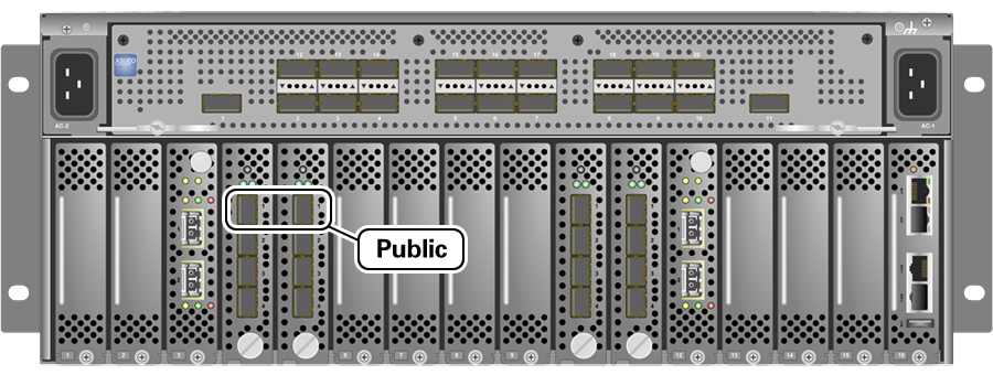
You must connect two 10 Gigabit Ethernet (GbE) IO module ports labeled “Public” on each Fabric Interconnect to your public Ethernet network.
The IO modules only support 10 GbE transport and cannot be connected to gigabit Ethernet switches. The Oracle Private Cloud Appliance must be connected externally to 10GbE optical switch ports.
Figure 3.3 shows the location of the 10 GbE Public IO module ports on the Fabric Interconnect.
It is critical that both Fabric Interconnects have two 10GbE connections each to a pair of next-level data center switches. This configuration with four cable connections provides redundancy and load splitting at the level of the Fabric Interconnects, the 10GbE ports and the data center switches. This outbound cabling should not be crossed or meshed, because the internal connections to the pair of Fabric Interconnects are already configured that way. The cabling pattern plays a key role in the continuation of service during failover scenarios involving Fabric Interconnect outages and other components.
Do not enable Spanning Tree Protocol (STP) in the upstream switch ports connecting to the Oracle Private Cloud Appliance.
Do not configure any type of link aggregation group (LAG) across the 10GbE ports: LACP, network/interface bonding or similar methods to combine multiple network connections are not supported.
To provide additional bandwidth to the environment hosted by the Oracle Private Cloud Appliance, create custom networks. For detailed information about network customization, refer to the Oracle Private Cloud Appliance Administrator's Guide.
Optional Data Center Administration Network Uplink
In addition to the public Ethernet connection, you may connect one of the two Oracle Switch ES1-24 switches to a management or machine administration network at your installation site. The system contains two Oracle Switch ES1-24 switches, making up one logical internal management network. The daisy-chained Oracle Switch ES1-24 arrangement has a special high availability (HA) configuration. Link tracking is done in software on the Oracle Switch ES1-24.
If you choose to use an uplink to the data center administration network, consider it as a long-term alternative to the temporary workstation connection described in Section 3.2.2, “IP Address Requirements for InfiniBand-based Systems”. Configure the administration uplink after the initialization of the appliance, when the appliance default network settings have been reconfigured.
Connect port 24 on one Oracle Switch ES1-24 – never both.
Make sure that the data center Ethernet switch used in this connection is configured to prevent DHCP leakage to the 192.168.4.0/24 subnet used by Oracle Private Cloud Appliance.
Use a workstation connected to the data center administration network and statically assign the IP address 192.168.4.254. Make sure there is no other machine directly connected to an internal Oracle Switch ES1-24, using the same IP address and causing IP conflicts.
A connection to the appliance internal management network, either directly into an Oracle Switch ES1-24 or through an additional Ethernet switch in the data center, is not required to access the appliance management functionality of the Oracle Private Cloud Appliance Dashboard. The primary role of the appliance internal management network is to allow the controller software on the management nodes to interact with the compute nodes and other rack components. Connecting to this network from outside the appliance allows you to gain direct administrator access to each component, for example to control the ILOMs.
The Oracle Private Cloud Appliance Dashboard, in contrast, is not accessed over the internal management network, but through the management node cluster's virtual IP address. The virtual IP address is public, in the sense that it should be accessible from within your data center network. You reserve this IP address in your data center network in advance, as described in Section 3.3, “General Network Configuration”, and then configure it in the appliance network settings during software initialization. Instructions for first access to the Oracle Private Cloud Appliance Dashboard are provided in Section 5.3.5, “Connect the Appliance to the Network”.
3.2.2 IP Address Requirements for InfiniBand-based Systems
The Oracle Private Cloud Appliance requires a large number of IP addresses. For lists of default IP addresses that are preassigned to your Oracle Private Cloud Appliance, see Appendix A, Default IP Addresses.
To gain initial access to the Oracle Private Cloud Appliance Dashboard, you must connect a terminal or workstation with a web browser directly to the management network. Connect an Ethernet cable to the available port 19 in one of the Oracle Switch ES1-24 switches, and statically configure the wired network connection of the workstation to use the IP address 192.168.4.254.
The IP address 192.168.4.254 is the only one available for customer use in the appliance management network.
During the initial software configuration of the Oracle Private Cloud Appliance, you reconfigure the network settings of the management nodes. For this purpose, you should reserve three IP addresses in the public (data center) network: one for each management node, and one to be used as virtual IP address by both management nodes. The virtual IP address provides access to the Dashboard once the software initialization is complete.
To avoid network interference and conflicts, you must ensure that the data center network does not overlap with any of the infrastructure subnets of the Oracle Private Cloud Appliance default configuration. These are the subnets you should keep clear:
-
192.168.140.0/24
-
192.168.40.0/24
-
192.168.4.0/24
3.3 General Network Configuration
Table 3.1 is a general network configuration worksheet to help you configure your Oracle Private Cloud Appliance. Oracle requests that you collect the information in preparation of the installation in your data center. The parameters entered in this worksheet are used as input during the initialization of the appliance.
|
Item |
Your Configuration |
Description and Example |
|---|---|---|
|
Domain Name |
Company network domain name.
Example:
|
|
|
Region |
Name of the country in which Oracle Private Cloud Appliance is installed. |
|
|
Time Zone |
Valid time zone. |
|
|
IP address of the Domain Name Server |
IP address of one or more network name servers (up to three servers).
Example: |
|
|
NTP Server |
IP address of a Network Time Protocol server.
Example: |
|
|
Search Domains |
A list of search domains for name lookup.
Example: |
|
|
Default Gateway |
IP address of the default gateway in your organization.
Example: |
|
|
IP address of Management node 1 |
IP address of the first management node in your company network.
Example: |
|
|
Host name of Management node 1 |
Host name of the first management node in your company network.
Example: |
|
|
IP address of Management node 2 |
IP address of the second management node in your company network.
Example: |
|
|
Host name of Management node 2 |
Host name of the second management node in your company network.
Example: |
|
|
Management virtual IP address |
Virtual IP address of the management node cluster in your company network.
Example: |
|
|
Management VLAN ID |
Data center VLAN tag for the management network, if applicable.
Example: VLAN tag |
|
|
vPC domain ID |
vPC domain ID for spine switches must be unique in your environment, the default value is 1.
Example: |