Preparing the Server for Component Replacement
This section describes safety considerations and provides prerequisite procedures and information about replacing components in the server.
Before you can remove and install components that are inside the server, you must perform the procedures in some or all of the following sections. For more information, see the component replacement procedures in this guide.
Safety Precautions
For your protection, observe the following safety precautions when setting up your equipment:
-
Follow all standard cautions, warnings, and instructions marked on the equipment and described in the "Oracle Server Safety and Compliance Guide" and "Important Safety Information for Oracle's Hardware Systems".
-
Ensure that the voltage and frequency of your power source match the voltage and frequency that appear on the equipment electrical rating label.
-
Follow the electrostatic discharge safety practices.
-
Disconnect both power supply cords (if necessary) before servicing components.
Note:
Power cords must be disconnected when servicing components that require cold service.
Safety Symbols
The following symbols might appear in this document. Note their meanings.
Caution:
Risk of personal injury or equipment damage. To avoid personal injury or equipment damage, follow the instructions.Caution:
Hot surface. Avoid contact. Surfaces are hot and might cause personal injury if touched.Caution:
Hazardous voltages are present. To reduce the risk of electric shock and danger to personal health, follow the instructions.Electrostatic Discharge Safety
Devices that are sensitive to electrostatic discharge (ESD), such as the motherboard, PCIe cards, drives, processors, and memory DIMMs require special handling.
Caution:
The boards and drives contain electronic components that are extremely sensitive to static electricity. Ordinary amounts of static electricity from clothing or the work environment can destroy components. Do not touch the components along their connector edges.Do the following when handling ESD-sensitive components:
-
Use an antistatic wrist strap.
Wear an antistatic wrist strap when handling components such as drive assemblies, boards, or cards. When servicing or removing server components, disconnect the power cords from the server. Attach an antistatic strap to your wrist and to a metal area on the chassis. Following this practice equalizes the electrical potentials between you and the server.
Note:
An antistatic wrist strap is not included in the Accessory Kit for the server. However, antistatic wrist straps are included with optional components. -
Use an antistatic mat.
Place ESD-sensitive components such as the motherboard, DIMMS (memory modules), and other printed circuit board (PCB) cards on an antistatic mat. The following items can be used as an antistatic mat:
-
Antistatic bag used to wrap an Oracle replacement part
-
Oracle ESD mat (orderable item)
-
Disposable ESD mat (shipped with some replacement parts or optional system components)
-
Powering Down the Server
Gracefully shut down the server host to prevent data from being corrupted. Performing a graceful shutdown ensures that the system is ready for restart. If the server is not responding, or you must shut down the server quickly, perform an immediate shutdown.
Note:
Components that are hot-pluggable do not require the server to be powered down. For more information, see the component replacement procedures in this guide.
Before Powering Down a Node
Servers in a Private Cloud Appliance rack are integrated components of a multinode environment. Unless a server experiences a sudden failure or must be shut down in an emergency situation, powering down server nodes in the appliance should be planned and performed carefully to minimize impact on the performance and availability of the appliance services and resources.
When planning to power down server nodes, take these points into account:
- System load
-
Powering down servers means system capacity is temporarily reduced. It makes sense to plan maintenance operations at a time when system load is typically at its lowest; for example during the night, over the weekend, and so on.
- Instance availability
-
Many workloads need to remain available while a server is offline for maintenance. You can live-migrate compute instances to other compute nodes in the same fault domain, or restart them in another fault domain. The available compute capacity in the three fault domains determines whether all workloads can remain operational or if some need to be scaled down or even interrupted temporarily.
- Maintenance mode
-
Before you can safely take a server offline, it must be placed in maintenance mode. In a Private Cloud Appliance environment this means that a compute node must not host any running compute instances, that it is under maintenance lock, and that provisioning has been disabled. An appliance administrator must perform these tasks from the Service Enclave.
For more information about locking nodes for maintenance, migrating compute instances, and configuring high availability in the Compute service, refer to the chapter Hardware Administration in the Oracle Private Cloud Appliance Administrator Guide.
Power Down a Node from the Service Enclave
Note:
Always perform a graceful shutdown. It ensures that all data is saved and the system is ready for restart.
-
Ensure that no compute instances are running on this node, and that the maintenance and provisioning locks are active.
-
From the Service Enclave, issue the Stop command.
See Hardware Administration in the Oracle Private Cloud Appliance Administrator Guide.
-
Service Web UI: In the Rack Units table, click the action menu (three vertical dots) and select Stop.
-
Service CLI: Enter the command
stop
                  ComputeNode id=<node-id>
.
-
Alternative Ways to Power Down a Node
If the Stop command from the Service Enclave does not cause the node to power down as expected, try these alternatives:
-
Use the Oracle Integrated Lights Out Manager (ILOM)
-
Log in to the ILOM UI or CLI using an Administrator account.
-
Perform a graceful shutdown.
-
ILOM UI: In the left pane, click Host Management, select Power Control, and click Graceful Shutdown and Power Off from the Select Action list. Click Save, and then click OK.
-
ILOM CLI: At the prompt, enter the command
stop /System.
-
-
-
Use the On/Standby Button
Press and quickly release the On/Standby button on the front panel.
This action causes ACPI-enabled operating systems to perform an orderly shutdown of the operating system.
The host server performs an orderly power shutdown to Standby power mode, and the System OK LED on the front panel begins blinking. Next, you can disconnect the cables from the server.
Disconnect Cables From the Server
Caution:
The system supplies Standby power to the circuit boards even when the system is powered off.
-
Ensure all cables connected to the server are labeled.
-
Power down the server.
-
Disconnect the power cords from the rear of the server.
-
Disconnect all data cables from the rear of the server.
-
Remove the cables from the cable management arm (CMA).
Extend the Server to the Maintenance Position
The following components can be replaced with the server in the maintenance position:
-
Fan modules
-
System battery
If the server is installed in a rack with extendable slide rails, use this procedure to extend the server to the maintenance position.
-
To prevent the rack from tipping forward when the server is extended, extend all rack anti-tilt mechanisms.
Refer to the "Oracle Rack Cabinet 1242 User's Guide" at Oracle Rack Cabinet 1242 Documentation Library.
-
Verify that no cables will be damaged or will interfere when the server is extended.
Although the cable management arm (CMA) that is supplied with the server is hinged to accommodate extending the server, ensure that all cables and cords are capable of extending.
-
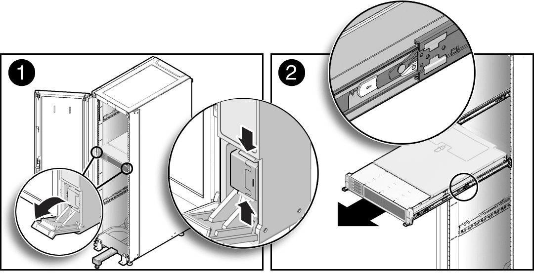
From the front of the server, open and hold the left and right release latch covers in the open position.
When in an open position, the release latch covers engage the slide rail release latches [1].
Caution:
Deploy any rack anti-tilt mechanism before releasing the slide rail release latches.
-
While the release latch covers are in the open position, slowly pull the server forward until the slide rails latch into a locked position [2].
The server is now in the extended maintenance position.
Take Antistatic Measures
-
Prepare an antistatic surface on which to set parts during removal and installation.
Place electrostatic discharge ESD-sensitive components such as the printed circuit boards on an antistatic mat. You can use the following items as an antistatic mat:
-
Antistatic bag used to wrap a replacement part
-
Oracle ESD mat (orderable item)
-
Disposable ESD mat (shipped with some replacement parts or optional system components)
-
-
Attach an antistatic wrist strap.
When servicing or removing server components, attach an antistatic strap to your wrist and then to a metal area on the chassis. Then perform procedures for servicing the server.
Note:
An antistatic wrist strap is not included in the Accessory Kit for the server. However, antistatic wrist straps might be included with options and components.
Remove the Server Top Cover
Replacing some components requires that the top cover be removed.
-
Ensure that AC power cords are disconnected from the server power supplies.
Note:
Fan modules are hot-pluggable and do not require AC power cables to be disconnected from the server power supplies. -
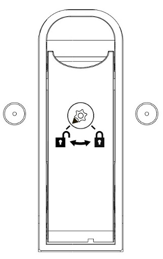
If the release button latch is in the locked position, use a Torx T15 screwdriver to turn the release button latch clockwise to the unlocked position.

-
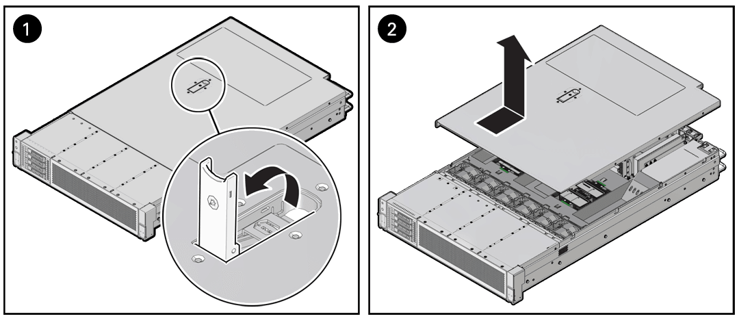
Unlatch the top cover [1].
Lift up on the release button on top of the server cover. Lifting the release button slides the server cover toward the rear of the chassis for easy removal.

-
Lift up and remove the top cover [2].