Returning the Server to Operation
This section describes safety considerations and provides procedures and information after replacing components in the server.
After replacing components inside of the server, perform the procedures in the following sections. For more information, see the component replacement procedures in this guide.
Install the Server Top Cover
-
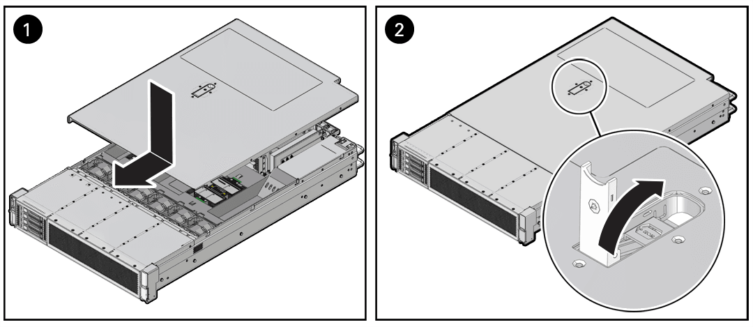
Place the top cover on the chassis [1].
Set the cover down so that it hangs over the back of the server by about 1 inch (25 mm) and the side latches align with the cutouts in the chassis.
-
Check both sides of the chassis to ensure that the top cover is fully down and flush with the chassis.
If the cover is not fully down and flush with the chassis, slide the cover towards the back of the chassis to position the cover in the correct position.
- Gently slide the cover toward the front of the chassis until it latches into place with
an audible click [2].
As you slide the cover toward the front of the server, the release button on the top of the server automatically rotates downward to the closed position. Latch the top cover by pushing down on the button until it is flush with the cover and you hear an audible click. An audible click indicates that the cover is latched.

-
Use a Torx T15 screwdriver to turn the release button latch counterclockwise to the locked position.
-
If you are done replacing server components, remove any antistatic straps or conductors from the server chassis.
Return the Server to the Normal Rack Position
If the server is in the extended maintenance position, use this procedure to return the server to the normal rack position.
-
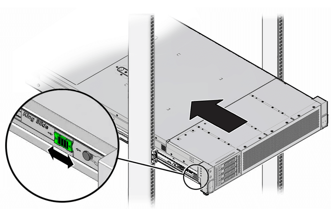
Push the server back into the rack, as described in the following steps.
-
Simultaneously pull and hold the two green release tabs (one on each side of the slide rails on the server) toward the front of the server, while you push the server into the rack.
Verify that the cable management arm (CMA) retracts without binding.
Note:
To pull the green release tab, place your finger in the center of the tab, not on the end, and apply pressure as you pull the tab toward the front of the server.
-
Continue pushing the server into the rack until the slide rail locks (on the front of the server) engage the slide rail assemblies.
You hear an audible click when the server is in the normal rack position.
-
-
If the CMA is not installed, because you removed the server completely out of the rack, install the CMA.
For installation instructions for the CMA, see Install the Cable Management Arm.
-
If the cables are disconnected from the back of the server, because you extended the server out of the rack, reconnect the cables. For instructions to reconnect cables to the back of the server, see Reconnect Power and Data Cables.
Reconnect Power and Data Cables
-
Reconnect the data cables to the back of the server, as appropriate.
Note:
If the cable management arm (CMA) is in the way, extend the server approximately 13 cm (5 inches) out of the front of the rack.
-
Reconnect the power cables to the power supplies.
-
Reinstall the cables into the cable management arm and secure them with Velcro straps.
Power On the Server
As soon as the power cords are connected, Standby power is applied. In Standby power mode:
-
The System OK LED on the server front panel blinks slowly.
-
The SP OK LED indicator is steady on.
-
The AC power supply LED indicator lights are steady on.
Power on the server to Main power mode by performing the following procedure:
-
From the Service Enclave, issue the Start command.
See Hardware Administration in the Oracle Private Cloud Appliance Administrator Guide.
-
Service Web UI: In the Rack Units table, click the action menu (three vertical dots) and select Start.
-
Service CLI: Enter the command
start
                ComputeNode id=<node-id>
.
-
-
If the Start command from the Service Enclave does not cause the node to boot as expected, try these alternatives:
-
Log in to the Oracle Integrated Lights Out Manager (ILOM).
-
ILOM UI: In the left pane, click Host Management, select Power Control, and click Power On from the Select Action list.
-
ILOM CLI: At the prompt, enter the command
start /System.
-
-
Press the On/Standby button on the front bezel.
-
When the server is powered on to Main power mode and the power-on self-test (POST) code checkpoint tests are complete, the green System OK LED status indicator on the front panel of the server lights and remains lit.